Note: Descriptions are shown in the official language in which they were submitted.
RIFLE SCOPE TARGETING DISPLAY ADAPTER MOUNT
[00011
BACKGROUND
100021 Aspects of the disclosure relate in general to the display of aiming
and target selection
information through a rifle scope.
[0003] Current military tactics call for combat snipers to work in close
coordination with a
spotter as part of a sniper team. The spotter provides protection and
situational awareness for
the sniper, since the sniper must devote substantial energy and attention to
positioning the
sniper rifle for an effective shot. Oftentimes, the spotter uses a targeting
computer that is
designed to provide aiming information appropriate for the sniper rifle being
used. Some
targeting computers provide the observer with a video feed of the target
environment and
compute aim point adjustments based on the wind, distance to target, target
movement and the
ballistic characteristics of the rifle being used.
[0004] When utilizing such a targeting computer, the spotter typically
provides the sniper
with a verbal description of the intended target as well as a vertical and
horizontal adjustment
factor. The sniper then manually moves the scope of the sniper rifle to
reflect the vertical and
horizontal adjustment factor. Once the scope is adjusted, the sniper can sight
the target with the
scope reticle for an accurate shot. However, this process requires the sniper
to remove his/her
hands from the firing position, which may cause the rifle to shift on the
rifle support. This
process may also require the sniper to momentarily take their eyes off the
target in order to
make manual adjustments. Communicating targeting information verbally between
the spotter
and the sniper can also generate noise and distractions that can give away the
sniper's position.
BRIEF SUMMARY
[0005] In some embodiments, an assembly for securely mounting a rifle scope
display
adapter (RDA) to the front of a scope body, the scope body having a threaded
interior surface
and an external surface, may include a first ring configured to be coupled to
the RDA and the
1
Date Recue/Date Received 2022-10-19
scope body. The first ring may include a threaded exterior surface that is
configured to mate
with the threaded interior surface of the scope body. The first ring may be
configured to be
coupled to the RDA such that the first ring can rotate around a center axis of
the first ring. The
assembly may also include a second ring configured to be coupled to the RDA
and scope body.
The second ring may be configured such that the external surface of the scope
body fits within
the second ring. The second ring may be configured to cause radial pressure to
be exerted
against the external surface of the scope body.
[0006] In some embodiments, a method for securely mounting a rifle scope
display adapter
(RDA) to the front of a scope body, the scope body having a threaded interior
surface and an
external surface, may include coupling a first ring to the RDA and the scope
body. The first
ring may include a threaded exterior surface that is configured to mate with
the threaded
interior surface of the scope body. The first ring may be configured to be
coupled to the RDA
such that the first ring can rotate around a center axis of the first ring.
The method may also
include coupling a second ring to the RDA and scope body. The second ring may
be
configured such that the external surface of the scope body fits within the
second ring. The
second ring may be configured to cause radial pressure to be exerted against
the external
surface of the scope body.
[0007] In some embodiments, one or more of the following features may also be
included in
any combination and without limitation. The RDA may include at least one
optical component,
and the first ring may be configured to be coupled to the RDA such that the
first ring can rotate
around a center axis of the first ring independent from rotation of the at
least one optical
component of the RDA. The second ring may include a collet having an
interdigitated pattern.
The second ring may include an outer ring with a flange and a threaded
surface, where the
flange may have substantially a same inside diameter as an outside diameter of
the scope body.
The flange may be configured to exert force against a collet as the threaded
surface of the
second ring is mated with a corresponding threaded surface. A third ring may
be present with a
sloped surface that translates the force exerted against the collet by the
flange into the radial
pressure to be exerted against the external surface of the scope body. The
first ring may be
configured to position the RDA flush with a front surface of the scope body
when the threaded
exterior surface of the first ring is mated with the threaded interior surface
of the scope body,
2
Date Recue/Date Received 2022-10-19
such that at least one optical component of the RDA is perpendicular to a
radial axis of the
scope body. A spacer ring may also be present having a first portion
configured to mate with a
uniform threaded internal surface of the RDA, and a second portion configured
to
accommodate scope bodies of varying diameters. The second ring may be
configured to be
coupled to the RDA through one or more additional assembly components. The
radial pressure
exerted against the external surface of the scope body may prevent the RDA
from rotating
relative to the scope body.
BRIEF DESCRIPTION OF THE DRAWINGS
[0008] For a more complete understanding of this invention, reference is now
made to the
following detailed description of the embodiments as illustrated in the
accompanying drawings,
in which like reference designations represent like features throughout the
several views and
wherein:
[0009] FIG. 1A is a block diagram of an example rifle scope display adapter.
[0010] FIG. 1B is a perspective diagram of an example rifle scope display
adapter.
[0011] FIG. 1C is an oblique, left-side view of an example rifle scope display
adapter.
[0012] FIG. 1D is a frontal view of an example rifle scope display adapter.
[0013] FIG. 2A is a block diagram of an example rifle scope display adapter
depicted
relative to components of a rifle scope to which the adapter is affixed.
[0014] FIG. 2B is a perspective diagram depicting a rifle scope to which an
example rifle
scope display adapter is affixed.
[0015] FIG. 2C is block diagram of a rifle scope display adapter that shows a
magnified
view of certain adapter components, and depicts a path of light relative to
these components.
[0016] FIG. 2D is a block diagram that shows an example light path relative to
components
of a rifle scope display adapter and components of a rifle scope to which the
adapter is affixed.
3
Date Recue/Date Received 2022-10-19
CA 02979882 2017-09-14
WO 2016/164618 PCT/US2016/026497
[0017] FIG. 3 is a diagram showing example paths of light rays within a rifle
scope display
adapter.
[0018] FIG. 4 illustrates one example of a view provided by a traditional
rifle scope.
[0019] FIG. 5A illustrates an RDA control and a view through a rifle scope
with an
uncalibrated RDA, according to some embodiments.
[0020] FIG. 5B illustrates a rotationally aligned virtual crosshairs that
needs to be vertically
and/or horizontally aligned, according to some embodiments.
[0021] FIG. 5C illustrates a rotationally and vertically aligned virtual
crosshairs that needs to
be horizontally aligned, according to some embodiments.
[0022] FIG. 5D illustrates a set of virtual crosshairs that are rotationally,
vertically, and
horizontally aligned with the crosshairs of the rifle scope, according to some
embodiments.
[0023] FIG. 6A illustrates an RDA control and a view through a rifle scope for
calibrating the
zoom function of an RDA, according to some embodiments.
[0024] FIG. 6B illustrates an example of a fully calibrated RDA, according to
some
embodiments,
[0025] FIG. 7A illustrates virtual symbols for gauging the precision of a
windage calculation
relative to a target, according to some embodiments.
[0026] FIG. 7B illustrates the visual elements of FIG. 7A after they have
graphically
converged, according to some embodiments.
[0027] FIG. 8A illustrates the chevron-style visual elements relative to the
silhouette in FIGS.
7A-7B, according to some embodiments.
[0028] FIG. 8B illustrates a visual element in the form of a circle
surrounding the silhouette,
according to some embodiments.
[0029] FIG. 9 illustrates a view of the target area through an RDA, according
to some
embodiments.
4
CA 02979882 2017-09-14
WO 2016/164618 PCT/US2016/026497
[0030] FIG. 10 illustrates a plurality of different targeting reticles that
can be selected by the
shooter during the configuration phase for the RDA, according to some
embodiments.
[0031] FIG. 11A illustrates a block diagram of an electrical system for an
RDA, according to
some embodiments.
[0032] FIG. 11B illustrates a block diagram of a second electrical system for
an RDA,
according to some embodiments.
[0033] FIG. 12 illustrates a flowchart of a method for displaying firing
solutions using a
display adapter that is configured to mount to a frame of a rifle scope,
according to some
embodiments.
[0034] FIGS. 13A-13D illustrate various views of one embodiment of an RDA
assembly,
according to some embodiments.
[0035] FIG. 14 illustrates an outside view and an inside view of the inner
ring, according to
some embodiments.
[0036] FIG. 15 illustrates an outside view and an inside view of the spacer,
according to some
embodiments.
[0037] FIG. 16 illustrates a collet, according to some embodiments.
[0038] FIG. 17 illustrates an outside view and an inside view of an outer
ring, according to
some embodiments.
[0039] FIG. 18 illustrates an RDA mount assembly for a large scope body,
according to some
embodiments.
[0040] FIG. 19 illustrates an RDA mount assembly for a smaller scope body,
according to
some embodiments.
[0041] FIG. 20 illustrates a flowchart of a method for securing and RDA to a
scope body,
according to some embodiments.
[0042] In the appended figures, similar components and/or features may have
the same
reference label. Further, various components of the same type may be
distinguished by
following the reference label by a dash and a second label that distinguishes
among the similar
CA 02979882 2017-09-14
WO 2016/164618 PCT/US2016/026497
components. If only the first reference label is used in the specification,
the description is
applicable to any or all of the similar components having the same first
reference label
irrespective of the second reference label.
DETAILED DESCRIPTION OF THE INVENTION
[0043] Several illustrative embodiments of a rifle scope display adapter will
now be described
with respect to the accompanying drawings, which form a part of this
disclosure. While
particular rifle scope display adapter implementations and embodiments are
described below,
other embodiments and alternative designs may be made without departing from
the scope of the
disclosure or the spirit of the appended claims.
[0044] According to some embodiments, a lightweight, compact rifle scope
display adapter
can be configured to be securely affixed to a rifle scope in front of the
scope's objective lens.
When attached to a rifle scope, the "rifle scope display adapter" (hereinafter
also referred to
interchangeably as a "display adapter" and/or an "adapter") can be operated to
supplement the
rifle scope view of the target by displaying aim point and/or trajectory
information computed by
a ballistic computer for a selected target. Specifically, the rifle scope
display adapter can provide
aim point information in the form of illuminated symbology that overlays the
target view seen
through the eyepiece of the scope. The adapter provides the symbology in such
a way that it
overlays the view provided by the rifle scope optics, without impeding a
sniper's view of the
target environment. In a simple form, the adapter enables a conventional scope
to be operated as
a "red dot" scope without any modification other than attachment of the
adapter to the scope to
the end of the rifle scope.
[0045] The rifle scope display adapter can be configured as a small and
lightweight unit that
can be tightly fastened to the front end of conventional magnifying rifle
scopes without requiring
any scope modification. A mechanical mounting fixture coupled to the adapter
allow the adapter
to be quickly attached to and removed from the rifle scope without equipment
such as wrenches
or screwdrivers. Additionally or alternatively, the rifle scope display
adapter may include
components for mounting the adapter immediately in front of a rifle scope
objective lens in such
a way that the adapter is coupled to and supported by the rifle itself,
without being affixed to the
scope. This disclosure primarily describes and illustrates embodiments of the
rifle scope display
6
CA 02979882 2017-09-14
WO 2016/164618 PCT/US2016/026497
adapter that include components for affixing the adapter directly to a rifle
scope. However, in
view of these descriptions and drawings, the design of alternative rifle scope
adapter
embodiments that facilitate direct mounting to a rifle would be readily
apparent to one of
ordinary skill in the art, and are therefore within the scope of this
disclosure.
[0046] The rifle scope display adapter may include optical elements,
processing circuitry,
mounting hardware, electrical connectors, and cabling. The rifle scope display
adapter may also
include light emitting circuitry. The illumination source of the symbology
that overlays the
image viewed through the rifle scope may be considered light emitting
circuitry, according to
some embodiments. The light emitting circuitry provides front lighting of a
liquid crystal on
silicon element that includes numerous reflective pixels, each of which can
reflect incident light
in a manner that can be varied by an electrical control signal. Within the
rifle scope display
adapter, the location, intensity, color and shape of aim point symbology
and/or video images is
controlled by electric signals that vary the reflection provided by individual
liquid crystal on
silicon (LCOS) reflective elements. By activating a particular combination of
reflective
elements while other reflective elements are inactive, the adapter projects
and directionally
controls light for illuminating a symbol or video image viewable through the
scope. The rifle
scope optics focus this projected light in such a way that it appears as
overlaying the image of the
target or other scene viewed through the scope.
[0047] While mounted in front of or attached to the rifle scope, the display
adapter can be
communicatively coupled to a targeting or ballistic computer wirelessly or by
way of a
connecting cable. The display adapter can be coupled to the computer
regardless of whether the
computer is also mounted on the rifle or detached and independently
manipulated by a spotter or
working in cooperation with a sniper.
[0048] The communicative coupling enables the display adapter to receive aim
point and
trajectory information computed by a ballistic computer. The aim point
information may include
an aim point displacement relative to the rifle scope reticle. In this case,
processing circuitry
within the adapter controls a combination of LCOS optical reflective elements
so that light
reflected from the LCOS, when focused at the rifle scope eyepiece, will be
seen to reflect the
specified offset relative to the reticle.
7
CA 02979882 2017-09-14
WO 2016/164618 PCT/US2016/026497
[0049] Alternatively or additionally, the optical system may receive raw image
data through
the connecting cable. The image data may consist of raw or compressed
pixilation data for the
display of symbology, video, or still images. The processing circuitry then
sets control signals
for the LCOS reflective elements so that each signal reflects the
corresponding pixel value in the
data.
[0050] The rifle scope display adapter may project an aim point indicator
symbol so that it is
observed as a small illuminated dot that overlays the natural image of the
target. In this way, the
shooter can move the rifle to place the projected aim point indicator on the
target instead of the
aim point of the rifle scope. By moving the rifle in this way, the shooter can
compensate for the
computed effect of windage and/or bullet drop without adjusting the scope,
looking away from
the scope image, changing his/her grip on the rifle, and/or manipulating a
ballistic computer.
[0051] FIG. 1A is a generalized block diagram showing an examplary
configuration of certain
light emitting components, optical components, and circuitry in the rifle
scope display adapter
40, according to some embodiments. FIG. lA is intended to be viewed in
conjunction with
FIGS. 1B-1D, which will be described together with FIG. IA. FIG. 1B is a
perspective diagram
of the rifle scope display adapter 40 from a vantage point to the front and
left of the adapter.
FIG. 1C is an oblique view of the rifle scope adapter 40 as seen from the left
side of the adapter.
FIG. 1D is a frontal view of the adapter 40. FIGS. 1A-1D depict the rifle
scope display adapter
40 in a standalone condition in which it is not attached to a rifle scope or
other rifle mounting
point.
[0052] In FIG. IA, certain components are depicted within a casing 44. The
casing 44, which
is also visible in FIGS. 1B-1D, may surround and enclose these components on
all sides, thereby
providing protection from the elements, as well as some degree of protection
from optical noise
and peripheral light that could otherwise interfere with the quality of the
images and symbols
projected when the display adapter is affixed to a rifle scope.
[0053] The components depicted within the casing 44 (which are explicitly
shown in FIG. 1A)
include processing circuitry 41, an LED 52, LCOS 39, diffuser (not shown in
FIG. 1A), polarizer
53, polarized beam splitter 51 (referred to hereinafter as a "first polarized
beam splitter" to
differentiate it from another similar component), moving telephoto lens 61 and
reflective element
54. The moving telephoto lens 61 provides parallax adjustment. Through
movement of a knob
8
CA 02979882 2017-09-14
WO 2016/164618 PCT/US2016/026497
94 mounted external to the casing 44 and visible in FIGS. 1B-1D, a shooter can
position the
telephoto lens 61 as needed to prevent parallax from affecting the view of the
target seen through
a rifle scope. A button interface 96 explicitly depicted in FIGS. 1B and IC
provides an interface
to the processing circuitry 41 so that display brightness, display mode, and
other display settings
can be adjusted.
[0054] The image processing circuitry 41 is also used to control, amongst
other things, the
light emitted by a light emitting diode (LED) 52. The LED 52 emits white light
that is the source
of the illumination used to project aim point symbology and video images when
the display
adapter 40 is attached to a rifle scope. Light emitted by the LED 52 is
reflected by the (LCOS)
39. The LCOS 39 includes several thousand reflective crystal elements, each of
which is
controlled by way of an electrical signal generated by the processing
circuitry 41. The
processing circuitry 41 controls the display of symbology or video images by
using these
electrical signals to cause reflections to occur at the LCOS in such a way
that the reflected light
is focused by the rifle scope optics, causing the desired to appear.
[0055] In FIG. 1A, these electrical signals are represented by the solid arrow
between the
processing circuitry 41 and the LCOS 39. The processing circuitry 41 includes
a connection port
92 at which a cable can be attached to connect the processing circuitry 41 to
an external ballistic
computer, targeting, and/or video generating device. The processing circuitry
41 processes aim
point and trajectory information, video data, nad/or image data received
through a cable attached
to connection port 92.
[0056] In FIGS. 1B-1D an intermediate cable 93 is depicted as being connected
to the
processing circuitry 41 at the connection port 92. The intermediate cable 93
includes a female
connecting port through which an electrical connection between a ballistic
computer and the
processing circuitry 41 of the display adapter 40 may be established. Other
embodiments may
additionally or alternatively include wireless communication means, such as a
radio frequency
(RF) transceiver, antenna, and/or the like.
[0057] The processing circuitry 41 may be designed to access aim point and
trajectory
infolination in the form of raw data representative of an aim point symbol
display location. The
display location may be specified as an offset from a rifle scope reticle. For
the purposes of this
disclosure, the rifle scope "reticle" refers to fixed crosshairs that are
positioned at the center of a
9
CA 02979882 2017-09-14
WO 2016/164618 PCT/US2016/026497
rifle scope image, or, more generally, to the center of the image seen through
a scope. The
reticle of the rifle scope may be peimanently etched into a glass element of
the rifle scope, and
may be contrasted with the projected targeting image displayed by the rifle
scope display
adapter. The aim point and trajectory information may alternatively be in the
form of pixel data
representing an image having an aim point symbol positioned to compensate for
computed
windage and bullet drop.
[0058] FIG. lA also depicts other optical components external to the casing
44, several of
which are also depicted in FIGS. 1B-1D. These components include a
transmissive light bar 55,
an additional polarized beam splitter 56 (hereinafter "second polarized beam
splitter"), a
spherical mirror 58 and a quarter-wave plate 57. As can be seen in FIG. 1B,
the light bar 55
diametrically traverses an annulus 60 on which the casing 44 is mounted. As
will be illustrated
in other drawings provided herein, the annulus 60 is configured to extend
forward of a rifle
scope's objective lens when the display adapter 40 is affixed to the scope.
When the display
adapter 40 is attached to a rifle scope, an aperture in the annulus 60 allows
light from the scene
to pass unimpeded to the objective lens of the scope. In this way, the optics
of the scope can
focus an image of the target at the eyepiece.
[0059] A series of arrows in three dimensions is also shown in FIG. 1A. This
series of arrows
is intended to provide a directional reference system that is consistent
across multiple different
viewing angles manifested in the drawings provided herein. These arrows (X,Y,
and Z) are
presented throughout the drawings in a manner that is consistent with respect
to the components
of the rifle scope display adapter, despite the difference in viewing angles
from one drawing to
the next.
[0060] FIG. 2A is a block diagram that shows the rifle scope display adapter
40 in a condition
in which it is affixed to a rifle scope 43. Other than for the fact that FIG.
2A shows the adapter
40 components relative to components of the rifle scope 43 to which the
adapter 40 is affixed,
the diagram of the display adapter 40 in FIG. 2A is similar to the display
adapter in FIG. 1A.
FIG. 2B, which is meant to be viewed in conjunction with FIG. 2A, is a
perspective diagram of
the display adapter 40 of FIG. 2A and the rifle scope 43 to which it is
affixed. FIG. 2B
represents a view of display adapter 40 and rifle scope 43 as seen from
slightly to the front and
left of the rifle scope 43.
CA 02979882 2017-09-14
WO 2016/164618 PCT/US2016/026497
[0061] As shown in FIGS. 2A and 2B, the rifle scope 43 includes an objective
lens 75 and
additional magnifying lenses 80. The rifle scope 43 also includes an eyepiece
76 through which
an image of a target or scene can be viewed. Moreover, symbols, images and
video can be
projected by the display adapter 40 and focused by the rifle scope 43 optics
so as to be visible at
the eyepiece 76. The display adapter 40 can provide these projections so that
they overlay the
view of the target or occupy the entire eyepiece 76.
[0062] The rifle scope display adapter 40 shown in FIGS. 2A and 2B is affixed
to the rifle
scope 43 with the annulus 60 of the adapter 40 surrounding the sides of the
rifle scope 43 at the
target end of the rifle scope 43. A portion of the annulus 60 extends slightly
forward of the
objective lens 75, in the direction of the target (x-direction, as shown by
the dashed arrow).
Also, the lightbar 55 traversers the aperture of the annulus 60 at a point
slightly forward of the
objective lens 75. It is important to note that several display adapter
components previously
depicted in FIG. 1A are also shown in FIG. 2A, but are too small to be
labeled.
[0063] FIG. 2C includes the depiction of the rifle scope display adapter 40
affixed to a rifle
scope 43, as previously seen in FIG. 2A and 2B. FIG. 2C also shows a magnified
view of the
rifle scope display adapter 40 components enclosed by the casing 44, as well
as a first portion of
a path of light emitted by the LED 52 during illumination of an aim point
symbol projected by
the adapter 40 and focused at the rifle scope eyepiece 76. A second part of
this path will be
shown in FIG. 2D.
[0064] The depiction of the path of light in FIGS. 2C and 2D is highly
generalized and is not
intended show angles of incidence, reflection and refraction. As such, these
drawings should be
understood as exhibiting only an approximate path of light relative to the
various components of
the rifle scope display adapter 40, as well as depicting certain adapter
components that reflect the
light within the casing 44 and certain components that transmit the light.
[0065] For example, FIG. 2C depicts that after light is emitted by the LED 52,
it is transmitted
and polarized by the polarizer 53. As a result of the polarization of the
light that occurs at the
polarizer 53, the light is reflected towards the LCOS 39 at the first
polarized beam splitter 51.
While the processing circuitry 41 controls the reflective pixel elements of
the LCOS 39, various
active pixel elements reflect the light back in the direction of the first
polarized beam splitter 51.
11
CA 02979882 2017-09-14
WO 2016/164618 PCT/US2016/026497
[0066] After being reflected at the LCOS 39, the light is transmitted by both
the first polarized
beam splitter 51 and the moving telephoto lens 61. The reflective element 54
then reflects the
light into the light bar 55.
[0067] FIG. 2D provides a generalized illustration of a second portion of the
path of light
illustrated in FIG. 2C. The second portion of the path of light begins at
reflective element 54, at
which point the light enters the light bar 55. Thus FIG. 2D is intended to be
viewed in
combination with FIG. 2C, which depicts the path of the light ray prior to its
exit from the casing
44 of the display adapter 40. As shown in FIG. 2D, the light enters the light
bar 55 after being
reflected at reflective element 54, is transmitted at the second polarizing
beam splitter 56 and is
reflected by the spherical mirror 58.
[0068] The light undergoes a polarity reversal imparted by the quarter-wave
plate 57 and is
then incident on the second polarizing beam splitter 56. The second polarizing
beam splitter 56
reflects the light towards the objective lens 75 of the rifle scope. The light
is incident on the
objective lens 75 near the center of the lens, while light from the scene is
incident on the
objective lens 75 between the center and periphery of the lens. The magnifying
80 lenses of the
rifle scope then refract and focus the light projected by the display adapter
40, as well as the light
emanating from the scene. In this way, the light projected by the display
adapter 40 is brought
into focus as a symbol or image visible at the eyepiece 76 of the rifle scope.
Simultaneously, the
light emanating from the scene is brought into focus at the eyepiece 76. In
this way, a shooter is
able to see a magnified view of the target with an overlaid aim point symbol
or other image
while looking through the rifle scope 43.
[0069] FIG. 3 is a schematic diagram showing the path of light rays in the
rifle scope display
adapter 40 during projection of a symbol or image visible through a rifle
scope. In FIG. 3,
depiction of the light emitted by the LED and the reflection of this light
towards the LCOS 39 is
omitted in order to avoid unnecessary complication of the drawing. Rather, the
rays shown in
the drawing are intended to illustrate the path of light only after its
reflection at the LCOS 39.
Additionally, the light path through the rifle scope is omitted in FIG. 3.
[0070] Although not shown, the LED 52 emits light towards a polarizing beam
splitter 51 that
is angled 45 degrees relative to the path of the light. Prior to reaching the
first polarizing beam
splitter 51, the light can be polarized by the polarizer 53. Optionally, the
light may be diffused
12
CA 02979882 2017-09-14
WO 2016/164618 PCT/US2016/026497
by a diffuser prior to reaching the first polarizing beam splitter 51 (e.g.,
the diffuser is disposed
between the LED 52 and the polarizing beam splitter 51), before or after the
polarizer 53. In
some embodiments the polarizer 53 may also act as a diffuser.
[0071] Also, a wire grid polarizer (not shown) is used to polarize the light
in such a way that it
will be reflected at the first polarizing beam splitter 51. Because of the
polarity of the light
incident on the first polarizing beam splitter 51,the beam splitter reflects
the light towards the
LCOS 39 (leftwards, as viewed in FIG. 3).
[0072] The processing circuitry 41 generates electrical control signals that
cause a combination
of LCOS reflective pixel elements to reflect the incident light. The LCOS 39
also reverses the
polarity of the light that it reflects. The light reflected by the LCOS 39 is
reflected back towards
the first polarizing beam splitter 51, where it is transmitted as a result of
the polarity reversal
imparted by the LCOS 39.
[0073] After being transmitted by the first polarized beamsplitter 51, the
light propagates
towards a moving telephoto lens 61 that provides parallax adjustment. The
light is divergently
refracted by the telephoto lens 61 in a manner that provides compensation
sufficient to prevent
parallax from affecting the rifle scope view.
[0074] Subsequent to being transmitted by the telephoto lens 61, the light is
incident on a
reflective element 54 that is disposed at an angle that is approximately 45
degrees from parallel
to the path of the light. The reflection of the light by the reflective
element 54 causes an
approximately 90 degree change in direction of the light. Following
reflection, the light
propagates through light bar 55. The light bar 55 may be shaped as a
rectangular prism formed
of a transmissive material that surrounds a second polarized beam splitter 56.
[0075] The second polarized beam splitter 56 is disposed within the light bar
55, and is
approximately centered with respect to the circular aperture (not shown in
FIG. 3) of the annulus.
By being centered with respect to the circular aperture, the second polarizing
beam splitter 56 is
disposed so that it will coincide with an extended optical axis (not
explicitly labeled) of the rifle
scope 43 to which the adapter 40 is affixed. That is, the second polarizing
beam splitter 56 will
be disposed directly in front of the center of the rifle scope objective lens
(not shown in FIG. 3).
13
CA 02979882 2017-09-14
WO 2016/164618 PCT/US2016/026497
[0076] As a result of the polarity of the light when reflected at reflective
element 54, the light
is transmitted by the second polarizing beam splitter 56 and is incident on
the spherical mirror 58
disposed at the end of the light bar 55 opposite the reflective element 54.
The spherical mirror
58 reflects the light towards the second polarizing beam splitter 56 and
reverses the polarity of
the light. Also, a quarter-wave plate 57 is disposed between the second
polarizing beam splitter
56 and the spherical mirror 58. The quarter-wave plate reverses the polarity
of the light.
[0077] As a result of the polarity reversal imparted by the quarter-wave plate
57, the second
polarizing beam splitter 56 reflects the light, causing a 90 degree change in
direction. As can be
seen in FIG. 3, the light rays are effectively collimated by the reflection
that occurs at the
spherical mirror 58 and second polarizing beam splitter 56. These collimated
light rays are then
incident at the objective lens of the rifle scope (not shown), which transmits
and refracts the rays
towards the optical eyepiece in the manner depicted in FIG. 2D.
RIFLE SCOPE DISPLAY
[0078] FIG. 4 illustrates one example of a view 402 provided by a traditional
rifle scope. The
view 402 shows a view of a long range target area 410 as seen through the
eyepiece of a
standalone magnifying rifle scope prior to installation of the rifle scope
display adapter described
herein. Shooting accurately at long ranges is not as simple as lining up a
crosshair 408 with a
target in the target area 410. For example, the environment between the rifle
scope and the target
area 410 may include strong crosswinds. Additionally, long-range shots need to
take the effect
of gravity into account, which causes a shot to drop between the rifle and the
target area 410. A
magnetic heading of the rifle may also affect long-range shots. A shot taken
under these
circumstances would drop and move to the right because of the strong left
crosswind and effect
of gravity over the lengthy distance to the target area 410.
[0079] Thus, to accurately hit targets in the target area 410 when using the
standalone rifle
scope shown in FIG. 4, a shooter would need to approximate an aimpoint above
and to the left of
the target. The shooter could approximate the aimpoint based on an estimation
of the strength of
the left cross-wind and the distance to the target area 410. The shooter could
then use the
aimpoint by manually aligning the crosshair above and to the left of the
target. However, this
14
CA 02979882 2017-09-14
WO 2016/164618 PCT/US2016/026497
methodology is very imprecise. The shooter could achieve better results by
mechanically
adjusting the rifle scope downwards and to the right using manual windage and
elevation knobs
that are included in most modern rifle scopes. However, making these
mechanical adjustments
can delay the shot and complicate the aiming process because the shooter's
hands must be
removed from the weapon, and may require the shooter to remove their eyes from
the rifle scope,
thus taking their eyes off the target. Also, the mechanical adjustment can
only be as precise as
the shooter's mental estimation of the necessary wind and elevation
compensation.
[0080] Alternatively, the shooter or an assisting spotter could use a
ballistic computer in
conjunction with a laser rangefinder to compute a compensatory scope
adjustment. The shooter
would then mechanically adjust the rifle scope downwards and to the right by
an amount
equivalent to the computed adjustment. The adjustment to the scope would cause
the rifle to
actually be pointed above and to the left of the target, while the crosshair
is seen as visually
aligned with the target to the shooter's eye. Although this methodology is
precise, it still
requires that the shooter's hands be removed from the weapon and the shooter's
eyes to be
removed from the target prior to the shot being taken.
[0081] In addition to illustrating the view 402 of the target area 410
provided by the traditional
rifle scope, FIG. 4 also illustrates markings that may be included as part of
a rifle scope. For
example, a crosshair 408 may be provided at the center of the rifle scope to
indicate a bore-
sighted aimpoint. Windage tick marks 404 may be used to help the shooter
adjust for windage
calculations/estimations. Elevation tick marks 406 may be provided to help the
shooter adjust
for bullet drop due to gravity. The crosshair 408, the windage tick marks 404,
and/or the
elevation tick marks 406 may be permanently etched into a glass element of the
rifle scope, or
alternatively may be implemented using visible wire elements inside the rifle
scope. In either
case, the crosshair 408, the windage tick marks 404, and/or the elevation tick
marks 406 of the
rifle scope may be permanently affixed to the rifle scope, and may be adjusted
by windage
and/or elevation knobs coupled to the outside frame of the rifle scope. These
permanent
markings in the rifle scope may be referred to herein as "visual rifle scope
elements."
[0082] In order to provide a more integrated and accurate method for
compensating for long-
range effects of a rifle shot, the embodiments described herein for a rifle
scope display adapter
(RDA) may project information and/or symbols onto the optical elements of the
RDA such that
CA 02979882 2017-09-14
WO 2016/164618 PCT/US2016/026497
the information and/or symbols are clearly and immediately visible to the
shooter through the
rifle scope. As will be described below, windage, elevation, azimuth angles,
tilt angles, and/or
rotation ("cant") angles can be automatically measured in real time and
displayed through the
RDA to the shooter. A ballistic computer can use each of these measurements as
inputs to
generate a targeting solution that moves a virtual targeting reticle to a
compensated location.
The shooter can align the compensated location of the virtual targeting
reticle through the rifle
scope with the target in the target area for an accurate shot without removing
his/her eyes from
the target and without manually adjusting the windage/elevation knobs of the
rifle scope,
[0083] In some embodiments, the RDA can be mechanically attached to the end of
the rifle
scope opposite the shooter's eyepiece. As described in detail above, the
optical components of
the RDA can display text and/or symbology through the optics of the rifle
scope such that they
are visible to the shooter. However, in order to ensure that the displayed
symbology is properly
scaled and aligned with the visual rifle scope elements, a calibration
procedure can first be
perfolined on the RDA as follows.
[0084] FIG. 5A illustrates an RDA control 502 and a view 510 through a rifle
scope with an
uncalibrated RDA, according to some embodiments. The RDA control 502 may be
physically
positioned on the side of the RDA as depicted in FIG. 1B (96). The RDA control
502 may
include a button 504 with a plus symbol, a button 508 with a minus symbol, and
a button 506
with a square symbol. Each of these buttons 504, 506, 508 can be used to
adjust the text and/or
symbols projected by the RDA during the calibration procedure. As used herein,
visual elements
projected by the RDA through the rifle scope may be referred to as "virtual"
elements or symbols
as opposed to the visual rifle scope elements that are also visible to the
shooter through the rifle
scope.
[0085] Because the RDA connects to the cylindrical end of the rifle scope, it
is likely that a
virtual crosshairs 514 will need to be rotated in order to align rotationally,
horizontally, and/or
vertically with the crosshairs 516 of the rifle scope. Instead of requiring
the shooter to physically
rotate the RDA on the end of the scope to align the virtual crosshairs 514,
the rotational
alignment can be performed electronically using the RDA control 502. For
example, pressing
button 504 can rotate the virtual crosshairs 514 counterclockwise, while
pressing button 508 can
rotate the visual crosshairs 514 clockwise. Button 506 can be pressed when the
rotational
16
CA 02979882 2017-09-14
WO 2016/164618 PCT/US2016/026497
alignment of the virtual crosshairs 514 is complete. Graphically, the RDA can
display a set of
coordinates 512 that shows a position of the virtual crosshairs during the
calibration procedure.
[0086] It will be understood that the buttons of the RDA control 502 are
merely exemplary and
not meant to be limiting. Other embodiments may use alternative types of
controls, such as
alpha-numeric keypads, touch screens, wireless controls, and/or the like.
[0087] FIG. 5B illustrates a rotationally aligned virtual crosshairs 514 that
needs to be
vertically and/or horizontally aligned, according to some embodiments. By
pressing button 506,
the calibration procedure can next move to a vertical alignment phase. The
functions of button
504 and button 508 can change from rotating the virtual crosshairs 514
clockwise/counterclockwise, and instead can shift the virtual crosshairs 514
vertically up/down.
By pressing button 506, the shooter can indicate that the vertical alignment
is complete. FIG.
5C illustrates a rotationally and vertically aligned virtual crosshairs 514
that needs to be
horizontally aligned, according to some embodiments. Similar to the process
described above,
pressing 504 and button 508 can horizontally shift the virtual crosshairs 514
to the left/right.
FIG. 5D illustrates a set of virtual crosshairs 514 that are rotationally,
vertically, and
horizontally aligned with the crosshairs 516 of the rifle scope.
[0088] The entire calibration procedure can be perfoitned by visually aligning
the virtual
crosshair hairs 514 with the permanent crosshairs 516 of the rifle scope.
Thus, the RDA can be
quickly attached to the end of the rifle scope without complicated or precise
installation
procedures. Instead, the positioning of the RDA can be performed
electronically without special
tooling and without extensive training. Furthermore, this calibration
procedure allows the RDA
to be used on a wide variety of rifle scopes without requiring specific
software and/or hardware
to accommodate each type of crosshair that may be available.
[0089] FIG. 6A illustrates an RDA control 502 and a view 510 through a rifle
scope for
calibrating the zoom function of an RDA, according to some embodiments. In
order to
accurately display adjustments to windage and elevation, the zoom factor of
the rifle scope must
be aligned with the zoom factor of the symbols and text displayed by the RDA.
After aligning
the virtual crosshairs 514 using the process described above, the zoom factor
may be calibrated
by aligning the tick marks 602 of the RDA with the tick marks 606 of the rifle
scope. During
this procedure, button 504 may be used to magnify the RDA display, while
button 508 may be
17
CA 02979882 2017-09-14
WO 2016/164618 PCT/US2016/026497
used to zoom out the RDA display. Again, the tick marks 602 of the RDA can be
aligned with
the tick marks 606 of the rifle scope visually without the need of special
equipment. When the
tick marks are aligned, the shooter can press button 506 to end this phase of
the calibration
procedure. FIG. 6B illustrates an example of a fully calibrated RDA, where the
virtual
crosshairs 514 are aligned with the crosshairs of the rifle scope, and the
zoom factor of the RDA
is aligned with the zoom factor of the rifle scope.
[0090] Once the RDA is calibrated with a properly bore-sighted rifle scope,
the virtual
crosshairs of the RDA can later be used to calibrate the crosshairs of the
rifle scope. There is
some drift or hysteresis in the windage and elevation adjustment knobs of many
rifle scopes.
The physical shock of each rifle shot may cause some physical movement of the
crosshairs due
to this inaccuracy inherent in mechanical adjustment knobs. Normally, shooters
would have to
re-bore sight their rifle after every 10 to 20 shots. Instead, the shooter can
follow the reverse
procedure described above, and align the crosshairs of the rifle scope with
the displayed virtual
crosshairs of the RDA through manual adjustment.
[0091] FIG. 7A illustrates virtual symbols for gauging the precision of a
windage calculation
relative to a target, according to some embodiments. A silhouette 702 can be
displayed to
illustrate the approximate dimensions of a target at a particular distance.
The silhouette 702 can
be scaled based on the zoom factor of the RDA as well as the distance to the
target. For
example, at longer distances, the silhouette 702 can be rendered smaller in
order to approximate
the size of the target at the greater distance when viewed through the rifle
scope.
[0092] A set of visual elements 704 can be used to graphically indicate a
precision with which
a windage calculation has been determined. Various electronic devices are
commercially
available that can be used to statistically estimate a windage calculation.
Light can be
transmitted from the device at the target and reflected back to a precision
camera to detect
scattering of the reflected light. As the scattered light is statistically
sampled over time,
algorithms for estimating a direction and velocity of wind between the
measurement device and
the target can converge to a precise value, Typically, the statistical
convergence of these
algorithms takes between 2s and 10s.
[0093] The visual elements 704 can be used to graphically indicate to the
shooter the degree to
which the windage measurement has converged. In the example of FIG. 7A, the
visual elements
18
CA 02979882 2017-09-14
WO 2016/164618 PCT/US2016/026497
704 include opposing chevrons that move towards the silhouette 702 as the
windage calculation
converges. When the calculation begins, the visual elements 704 may be spread
relatively wide,
leaving the silhouette 702 alone in the middle of the RDA view. As the windage
calculation
converges, the visual elements 704 will gradually move inwards until they
close in on the
silhouette 702. FIG. 7B illustrates the visual elements 704 of FIG. 7A after
they have
graphically converged on the silhouette 702, indicating that the windage
measurement has also
converged.
[0094] The visual elements 704 of FIGS. 7A-7B are merely exemplary and not
meant to be
limiting. Any other type of graphical elements may be used to illustrate
convergence of a
windage calculation. FIG. 8A illustrates the chevron-style visual elements 804
relative to the
silhouette 802 described above in FIGS. 7A-7B. In another example, FIG. 8B
illustrates a visual
element 808 in the form of a circle surrounding the silhouette 806. As the
windage calculation
converges, the visual element 808 can shrink until it is relatively close to
the silhouette 806.
[0095] FIG. 9 illustrates a view of the target area 410 through an RDA,
according to some
embodiments. As shown in FIG. 9, the RDA may be operated by a shooter in an
aimpoint
assistance mode. Although not depicted in FIG. 9, the RDA may be
communicatively connected
to a ballistic computer (e.g., via wired and/or wireless communication). The
ballistic computer
may be operated by a spotter working in the shooter's vicinity, or maybe
integrated into a system
on the rifle scope itself. In some embodiments, a ballistic computer may also
operate on the
processor of the RDA locally.
[0096] In one configuration, the ballistic computer can receive inputs for
environmental
sensors and compute a firing solution. Inputs to the ballistic computer may
include a target
range as determined by laser rangefinder, a magnetic bearing or azimuth angle
(e.g., X
Northwest, r South, etc.), a tilt angle of the rifle, a cant angle of the
rifle, and/or a wind
measurement. Each of these inputs may be provided by external systems, or may
be provided by
sensors integrated onto the RDA itself. Regardless of whether these
measurements are provided
by the RDA itself or by an external system, the measurement results can be
displayed in real time
on the RDA for the shooter. For example, FIG. 9 illustrates a range
measurement 902, an
azimuth angle measurement 904 (to be used to compensate for the Coriolis
effect of the Earth's
rotation), an altitude angle measurement 906, and/or a cant angle measurement
908 that are
19
displayed in real time for the shooter. As the shooter moves or rotates the
rifle, the
measurements 902, 904, 906, and 908 can be dynamically updated on the RDA such
that the
change is immediately visible to the shooter.
[0097] In some embodiments, the altitude angle measurement 906 and the cant
angle
measurement 908 can be provided from the RDA as inputs to the ballistic
computer to calculate a
targeting solution. In other embodiments, the display of altitude angle
measurement 906 and the
cant angle measurement 908 can be merely informational for the shooter. In
response, the
shooter can rotate or adjust the altitude angle of the rifle until they are
close to 0.0 as shown in
real-time on the RDA display.
[0098] The ballistic algorithms used to calculate a firing solution are beyond
the scope of this
disclosure. Algorithms capable of calculating firing solutions may be
commercially available
from companies such as Applied Ballistics and/or Kestrel . A wind measurement
sensor is
described in the commonly assigned U.S. Patent No. 9,678,099 filed on April
24, 2015.
[0099] The output of the firing solution may be comprised of a windage
adjustment and an
elevation adjustment to be applied by the shooter to the rifle scope. Like the
input measurements
902, 904, 906, and 908, the firing solution can also be displayed in real time
as it is calculated
through the RDA. For example, an elevation adjustment 914 can be displayed, as
well as a
windage adjustment 916. The units for the elevation adjustment 914 and the
windage adjustment
916 can be set during the calibration phase according to the units used by the
rifle scope itself.
For example, the rifle scope in FIG. 9 uses "mils" (MRADS, or milliradians),
while other rifle
scopes may instead use Minutes of Angle (MOA).
[0100] The range and windage measurements may be calculated using algorithms
based on a
laser being reflected from a target. Because there is some calculation time
involved, visual
indicators may be provided by the RDA to indicate to the shooter when those
calculations are
complete. For example, an "R" symbol 912 may be dynamically displayed to
indicate that the
range calculation has been completed. Similarly, a "W" symbol 910 may be
dynamically
displayed to indicate that the windage calculation has been completed. Before
these calculations
are completed, the R symbol 912 and/or the W symbol 910 may be absent from the
display.
These measurements may be displayed in addition to the chevron symbols 922
and/or the
Date Recue/Date Received 2022-10-19
CA 02979882 2017-09-14
WO 2016/164618 PCT/US2016/026497
silhouette 918 described above to indicate the degree to which the displayed
windage
measurement has been able to converge.
[0101] In traditional rifle scopes, the shooter would be required to manually
adjust the windage
and/or elevation knobs on the rifle scope in order to reposition the permanent
crosshairs of the
rifle scope. Alternatively, the shooter could reposition the rifle using the
tick-mark scale on the
rifle scope in order to estimate a correct shot. Either of these solutions led
to inaccuracy or
forced the shooter to take his/her hands off the rifle in order to make manual
adjustments.
[0102] In contrast, the embodiments described herein can use the firing
solution calculated by
the ballistic computer and automatically display a targeting reticle 924 that
is correctly
positioned according to the calculated windage and elevation adjustments. For
example, if the
tree in the target area 410 is the desired target, the shooter can aim the
rifle such that targeting
reticle 924 is in line with the target. This can be done without making any
manual adjustments
and without taking eyes off the target. Furthermore, instead of estimating how
far the rifle needs
to be raised or shifted horizontally, the shooter can simply position the
targeting reticle 924 over
the target. The targeting reticle 924 can be repositioned each time a new
windage/range
calculation is completed. Therefore, by using the targeting reticle 924 to
target the rifle, the
shooter can automatically incorporate all targeting solution calculations into
the targeting reticle
924 for an accurate shot.
[0103] In some embodiments, the wind sensor and/or the laser rangefinder may
be
incorporated into the RDA or into a unit attached to the rifle or rifle scope.
In these
embodiments, the center of the rifle scope crosshairs (e.g., the silhouette
918) would first need to
be pointed at the at the target so that a range/windage measurement to be
taken. Once the
range/windage calculations are completed, the targeting reticle 924 will
appear, and the shooter
can reposition the rifle such that the targeting reticle 924 is on the target.
[0104] As was the case with the graphical elements for indicating convergence
of the windage
calculation algorithm, the actual visual representation of the targeting
reticle can include a
number of different embodiments. FIG. 10 illustrates a plurality of different
targeting reticles
1002 that can be selected by the shooter during the configuration phase for
the RDA.
21
CA 02979882 2017-09-14
WO 2016/164618 PCT/US2016/026497
[0105] FIG. 11A illustrates a block diagram of an electrical system for an RDA
1102,
according to some embodiments. The RDA 1102 may include one or more processors
1104.
The processor(s) 1104 may include ¨ or may be communicatively coupled to ¨ a
memory device
that stores a set of instructions that causes the processor(s) 1104 to perform
operations that
collect sensor data, communicate with a ballistic computer, and/or display
text and/or symbols
on the optical components of the RDA 1102. In some embodiments, the RDA 1102
may include
a ballistic computer 1130 as part of the processor(s) 1104, or as a separate
processor (not shown).
In other embodiments, a ballistic computer may be provided by an external
device, such as a
Kestrel device. Communication with the external ballistic computer may be
transmitted
through a physical connector 1108 and/or through a wireless communications
module 1114. The
wireless communications module 1114 may include a Wi-Fi transmitter/receiver,
a Bluetooth
transmitter/receiver, and/or a transmitter/receiver operating at another radio
frequency.
[0106] The processor(s) 1104 may receive commands as well as a firing solution
from the
ballistic computer 1130. The RDA 1102 may also include a symbol generator 1106
that can
accept a set of commands to generate vector graphics on the RDA optical
display interface 1110.
As described above, a beam splitter may be included as one of the optical
components of the
RDA optical display interface 1110. A portion of the light received through
the beam splitter
may be directed into a daylight sensor 1112. Measurements from the daylight
sensor 1112 can
be fed into the processor(s) 1104 in order to dynamically adjust the
brightness of the graphics
displayed through the rifle scope on the RDA. For example, against a white
background in
daylight, the brightness of the display can be dynamically and automatically
adjusted to be
brighter. In contrast, against a dark background or at night, the brightness
of the display can be
dynamically and automatically adjusted to be dimmer.
[0107] The RDA 1102 may include one or more sensors that are communicatively
coupled to
the processor(s) 1104 through a communication bus 1116. In some embodiments,
the
communication bus 1116 may comprise an I2C bus. In some embodiments, the RDA
1102 may
include a magnetic heading sensor 1118 to measure an azimuth angle of the
rifle. In some
embodiments, the RDA 1102 may include a gravitational tilt sensor 1120 to
measure the tilt
and/or rotation angle of the rifle with respect to a gravitational vector. In
some embodiments, the
RDA 1102 may also include a laser rangefinder 1122. The laser rangefinder may
be an
22
CA 02979882 2017-09-14
WO 2016/164618 PCT/US2016/026497
integrated part of the RDA optical display interface 1110. Alternatively, the
laser rangefinder
1122 can be an external sensor rather than an integrated part of the RDA 1102.
Similarly, a
windage sensor 1124 may be an integrated part of the RDA 1102 and/or may be
externally
provided. Sensors that are externally provided may communicate directly with
an external
ballistic computer, and/or may communicate with the processor(s) 1104 through
the connector
1108.
101081 FIG. 11B illustrates a block diagram of a second electrical system for
an RDA,
according to some embodiments. The electrical system of FIG. 11B may be
considered a
specific implementation of the more generic electrical system of FIG. 11A. In
order to provide
an enabling disclosure, specific part numbers may be provided for the major
components in FIG.
11B. However, these part numbers are merely exemplary and not meant to be
limiting. One
having skill in the art would readily understand that many other specific
parts may be used that
provide the same or similar functionality.
101091 A keypad 1132 may function as the RDA control described above for
calibrating and
operating the user interface of the RDA. An external connector 1134 can
receive serial
communications (e.g., RS-232) from external components, such as a ballistic
computer, a
windage sensor, a laser rangefinder, and/or the like. The external connector
1134 can also
receive instructions to program a microprocessor 1138 (e.g., LPC1347) through
a serial line
driver/receiver 1136 (e.g., ADM3101). Power may be provided externally through
the external
connector 1134 and/or through a user-replaceable battery 1142 (e.g., CR-123A).
In addition to
receiving communications through the external connector 1134, the RDA can
receive
communications through a wireless connection, such as a Bluetooth antenna
1150.
[0110] Sensors integrated into the RDA may include a linear accelerometer for
measuring the
tilt of the RDA with respect to a gravity vector and/or a magnetic heading
sensor 1140. In some
embodiments, these two sensors can be integrated into the same package (e.g.,
LSM9DS0). The
RDA may also include a daylight sensor 1132 that is configured to receive
light from a beam
splitter in the optical components of the RDA. For example, the daylight
sensor 1132 may
include a photodiode that generates a response that is proportional to the
amount of light
received through the optics of the RDA to automatically adjust the brightness
of the display. In
order to generate the text and/or symbols displayed by the RDA, an LCOS
Display 1148 (e.g.,
23
CA 02979882 2017-09-14
WO 2016/164618 PCT/US2016/026497
SYL2271), an LCD controller processor 1144 (e.g., SYA1231), and a Graphics
Processing Unit
(e.g., FT810) may also be included.
[0111] FIG. 12 illustrates a flowchart of a method for displaying firing
solutions using a
display adapter that is configured to mount to a frame of a rifle scope,
according to some
embodiments. The method may include sending position information of the RDA
from the RDA
to a ballistic computer (1202). In some embodiments, the position information
may include a tilt
angle of the RDA as measured by a linear accelerometer or other gravitational
tilt sensor. The
position information may also include a magnetic heading.
[0112] The method may also include receiving, at the RDA, a firing solution
from the ballistic
computer (1204). The firing solution may include a windage adjustment and/or
an elevation
adjustment. The method may further include displaying a targeting reticle on a
display device of
the RDA (1206). In some embodiments, the targeting reticle may be displayed
relative to a
crosshair of the rifle scope according to the firing solution as described in
detail above. Some
embodiments may also display a calculated windage measurement and/or a
calculated range to a
target. A graphic may also be displayed that visually indicates a convergence
of a windage
calculation algorithm. The graphic may include graphical elements that
visually converge on a
center point as the windage calculation algorithm converges (e.g., FIGS 8A-
8B). The targeting
reticle may be displayed such that the targeting reticle overlays an image
visible through the
eyepiece of the rifle scope. Thus, a shooter looking through the rifle scope
may see the normal
image of the targeting area along with the text in symbols projected by the
RDA through the rifle
scope.
[0113] In order to calibrate the RDA, a control pad may be provided through
which inputs can
be received. Inputs received through the control can be used to visually align
the crosshair of the
rifle scope with a crosshair projected by the RDA. For example, such inputs
can rotate,
horizontally shift and/or vertically shift the crosshair projected by the RDA
relative to the
crosshair of the rifle scope.
[0114] It should be appreciated that the specific steps illustrated in FIG. 12
provide particular
methods of displaying information through an RDA according to various
embodiments of the
present invention. Other sequences of steps may also be performed according to
alternative
embodiments. For example, alternative embodiments of the present invention may
perform the
24
CA 02979882 2017-09-14
WO 2016/164618 PCT/US2016/026497
steps outlined above in a different order. Moreover, the individual steps
illustrated in FIG. 12
may include multiple sub-steps that may be performed in various sequences as
appropriate to the
individual step. Furthermore, additional steps may be added or removed
depending on the
particular applications. One of ordinary skill in the art would recognize many
variations,
modifications, and alternatives.
RIFLE SCOPE DISPLAY MOUNT
[0115] The rifle scope display adapter (RDA) described above is designed to
provide an
accurate targeting solution on a display through a rifle scope to a shooter
such that the shooter
can keep their eyes on the target at all times. In order to guarantee the
accuracy of the virtual
targeting reticle of the firing solution, the RDA must be securely affixed to
the rifle scope such
that the RDA does not shift, rotate, or move between shots. However, the RDA
should not be
permanently secured to the rifle scope because the rifle scope itself is a
modular unit, one that
may be replaced, calibrated, and/or damaged. Thus, not only must the RDA be
securely affixed
to the rifle scope, it also should be removable. Finally, hundreds of
different long-range rifle
scopes are available, each having different ranges, precision manufacturing
requirements, and
uses. Therefore, a mount assembly used to secure the RDA to the scope should
be able to
accommodate all of the available different scope diameters.
[0116] Prior to this disclosure, accessories mounted in front of the rifle
scope on a rifle could
be attached using one of two methods. First, many rifle scopes include a
threaded section on the
interior of the scope body in front of the front lens. Accessories can be
screwed into the front of
the scope using these interior threads. For example, a lightweight accessory
known as a "flash
kill" can be screwed into the front of a rifle scope in order to block light
reflections off the front
of the scope lens that could give away the position of the shooter. While
these threads may be
used to secure lightweight accessories, heavier accessories, such as the RDA
described above,
are too heavy to be secured using these threads alone. Furthermore, the shock
generated by high-
powered rifles is often sufficient to gradually loosen and accessory from
these threads. Even a
few millimeters of rotation of the RDA would skew the calibrated targeting
image and result in
an inaccurate virtual targeting reticle. Second, some rifle accessories may be
mounted in front of
the scope on a "Picatinny" or other rail system. While affixing an accessory
to the rail may be
CA 02979882 2017-09-14
WO 2016/164618 PCT/US2016/026497
secure, small amounts of play in the rail assembly, the mounting fixture, the
scope mount, and
the accessory, may add up to an unacceptable amount of movement between the
accessory and
the scope between shots.
[0117] In order to solve these and many other problems, the embodiments
described herein
present a method of mounting the RDA directly to the front of the scope in a
secure and
removable manner. These embodiments guarantee that the RDA does not move,
rotate, or shift
between shots of high-powered rifles. These embodiments also allow a common
RDA projector
display to be mounted to differently sized rifle scopes having variable
diameters. These
embodiments also make certain that the RDA is seated properly against the
scope so that the
projected image is not skewed through the scope lens.
[0118] A first aspect of these embodiments provides a threaded ring that can
be screwed into
the interior threads of the existing scope body. The threaded ring ensures
that the RDA projector
display is seated perpendicular to the optical path of the scope by pulling
the RDA flush against
the front of the scope body. A second aspect of these embodiments keeps the
threaded ring on
the interior of the scope body from loosening by providing radial pressure
directed inwards
towards the body of the scope via a second ring around the exterior of the
scope. This radial
pressure is exerted using the second ring on the outside of the scope body.
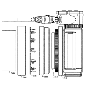
[0119] FIGS. 13A-13D illustrate various views of one embodiment of an RDA
assembly,
according to some embodiments. The assembly may be comprised of a plurality of
individual
components used to mate the RDA common display projector ("display projector")
1312 to a
scope body 1302. The display projector 1312 may be provided in a single size,
and the
remaining components of the assembly can include interchangeable members of
variable sizes to
accommodate scope bodies with different diameters. Therefore, only a single
display projector
1312 ¨ which includes the optical components, electrical components and
connectors,
controllers, sensors, and processors described in detail above ¨ needs to be
designed and
manufactured, and the remaining components in the assembly can be used to
secure the display
projector 1312 to virtually any size of rifle scope.
[0120] It will be understood that the specific components in the assembly
depicted in FIGS.
13A-13D are merely exemplary and not meant to be limiting. Functionally, these
components
provide the two aspects described above: (1) a first ring that mates with the
threads on the
26
CA 02979882 2017-09-14
WO 2016/164618 PCT/US2016/026497
interior of the scope body 1302 and secures the display projector 1312 flush
with the front of the
scope body 1302; and (2) a second ring that exerts radial compressive force
against the exterior
of the scope body 1302. In light of this disclosure and these two aspects, one
having skill in the
art could alter the assembly components described below into alternate
geometries in order to
provide the same functionality. Such modifications are within the scope of
this invention.
[0121] In some embodiments, the assembly is comprised of an outer tightening
ring ("outer
ring") 1304, a collet 1306, a spacer adapter ("spacer") 1308, and an inner
fingertip grip filter
thread tightening ring ("inner ring") 1310. To describe the functionality of
each of these
individual components, FIGS. 14-17 each depict a single component apart from
the assembly. In
the accompanying description below, reference will be made back to FIGS. 13A-
13D to illustrate
how the components are assembled to attach the display projector 1312 to the
scope body 1302.
[0122] Beginning with the inner ring 1310, FIG. 14 illustrates an outside view
1402 and an
inside view 1404 of the inner ring 1310, according to some embodiments. A
portion of the
display projector 1312 is also illustrated in order to show how the inner ring
1310 seats within
the display projector 1312. The inner ring 1310 may be comprised of two rings
of different
diameters. A threaded ring 1404 may include screw threads (not shown for
clarity) on the
outside surface of the threaded ring 1404. A grip ring 1406 may include a
grippable surface on
the outside surface of the grip ring 1406. The grip surface may include a
diamond pattern, small
ridges and/or valleys, a scored surface, a sandpaper-like surface, and so
forth. The grip ring
1406 and the threaded ring 1404 may be manufactured from a single block of
material (e.g.,
machined from a single piece of aluminum), or they may be manufactured
separately and joined
together. In either case, the grip ring 1406 and the threaded ring 1404 will
turn in unison as the
grip ring 1406 is rotated.
[0123] The grip ring 1406 may be a constant diameter regardless of the scope
diameter. The
grip ring 1406 may include a flange 1410 that is sized to mate with a
corresponding groove or
recess in the display projector 1312. During assembly, the flange 1410 of the
grip ring 1406 may
be seated within the corresponding groove or recess in the display projector
1312 such that the
grip ring 1406 can rotate freely radially around its center diameter. However,
the corresponding
groove or recess in the display projector 1312 prevents the inner ring 1310
from shifting or
moving perpendicular to the center diameter of the inner ring 1310.
27
CA 02979882 2017-09-14
WO 2016/164618 PCT/US2016/026497
[0124] The threaded ring 1404 may be manufactured in varying diameters to
accommodate the
varying diameters of different scope bodies. For example, some embodiments of
the threaded
ring 1404 may be sized to accommodate the interior diameter and threads of a
scope body of a
Leupold MK4 ER/T 50mm 6.5-20x50mm Army M2010 scope. Other embodiments of the
threaded ring 1404 may be sized to accommodate a Leupold USSOCOM ECOS-0 MK6 3-
18x44mm scope, or a Schmidt & Bender 5-25x56mm PM!! USSOCOM PSR scope. In
addition to these exemplary scope models, and in light of this disclosure, one
having skill in the
art would be able to measure the internal diameter and thread spacing of any
scope and design a
threaded ring 1404 accordingly.
[0125] After the inner ring 1310 is seated in the display projector 1312, the
grip ring 1406 is
accessible to a user through an opening 1412 in the body of the display
projector 1312.
Although not shown in the outside view 1402 or in FIGS. 13A-13C, the dashed
lines of the
inside view 1404 show a ring 1408 of the display projector 1312 that extends
over the inner ring
1310. The user is able to rotate the inner ring 1310 by gripping the grip ring
1406 through the
opening 1412, which extends around at least a portion of the ring 1408. Thus,
the inner ring can
be rotated through the opening 1412 of the display projector 1312 in order to
mate the threads of
the threaded ring 1404 with the threads of the inside of the scope body 1302.
The ring 1408 of
the display projector 1312 may include threads on the interior (not shown for
clarity) of the ring
1408 in order to mate with the spacer 1308 as described in greater detail
below.
[0126] FIGS. 13A-D and FIGS. 14-17 illustrate components sized for a 50mm
scope body. To
illustrate how the size of the assembly components can change in order to
accommodate both
larger and smaller sizes, FIG. 18 illustrates a 56 mm scope body, and FIG. 19
illustrates a 44
mm scope body. Note that the threaded ring of the inner ring 1310 in FIG. 18
is larger to
accommodate the 56 mm scope, and the threaded ring of the inner ring 1310 in
FIG. 19 is
smaller to accommodate the 44 mm scope. In contrast, the grip ring for all
three scope sizes can
remain the same.
[0127] FIG. 15 illustrates an outside view 1502 and an inside view 1504 of the
spacer 1308,
according to some embodiments. After seating the inner ring 1310 in the
display projector 1312,
the spacer 1308 can be screwed into the display projector 1312 to hold the
inner ring 1310 in
place. Like the inner ring 1310, the spacer can be functionally divided into
two different external
28
CA 02979882 2017-09-14
WO 2016/164618 PCT/US2016/026497
diameters, namely a large ring 1508 disposed closer to the scope body 1302,
and a small ring
1506 disposed closer to the display projector 1312. The small ring 1506 may
include threads
(not shown for clarity) on the external surface of the small ring 1506 in
order to mate with the
corresponding threads on the inner surface of the ring 1408 of the display
projector 1312.
Similarly, the large ring 1508 may include threads (not shown for clarity) on
the external surface
of the large ring 1508 for mating with corresponding threads on the outer ring
1304 as described
in greater detail below.
[0128] After screwing the spacer 1308 into the display projector 1312, the
inner ring 1310 will
be held in place such that it can rotate around its center axis, but cannot
shift off that center axis
or along the center axis. As illustrated in FIG. 13C, a surface 1510 of the
small ring 1506 will
seat against the side of the grip ring 1406 of the inner ring 1310, holding
the inner ring 1310 in
place. The threaded ring 1404 of the inner ring 1310 will extend through the
opening inside the
surface 1510 of the small ring 1506 to screw into the inside threads of the
scope body. An
opposite surface 1514 of the small ring 1506 will seat against the front of
the scope body 1302.
Therefore, when the spacer 1308 and the inner ring 1310 are assembled with the
display
projector 1312, the inner ring 1310 can be screwed into the inside threads of
the scope body 1302
until the opposite surface 1514 of the spacer 1308 is flush with the front of
the scope body 1302.
This ensures that the optical display elements of the display projector 1312
are parallel with the
scope lens, or perpendicular to the center axis of the scope. Thus, the inner
ring 1310 and the
spacer 1308 provide for the first aspect described above for mounting the RDA
to the scope body
1302 by providing a threaded attachment that can be screwed into the front of
the scope body
1302 to ensure that the optical components of the display projector 1312 are
not skewed in
relation to the scope lens.
[0129] In some embodiments, the spacer 1308 may also help provide for the
second aspect
described above for mounting the RDA to the scope body 1302 by translating
radial pressure
against the external surface of the scope body 1302. As will be described in
greater detail below,
the interior of the spacer 1308 includes a sloped surface 1512 that will cause
a compressible ring,
such as the collet 1306, to be compressed against the scope body 1302 as the
compressible ring
and the spacer 1308 move towards each other. The outside diameters of the
large ring 1508 and
the small ring 1506 for the spacer 1308 may be the same for different sized
scopes. However,
29
CA 02979882 2017-09-14
WO 2016/164618 PCT/US2016/026497
because the outside diameter of each scope will change, the diameter of the
compressible ring
will also need to change to match the outside diameter of each scope body
1302. Therefore, the
interior radius of the spacer 1308 with the sloped surface 1512 will grow or
shrink based on the
diameter of the scope and the compressible ring. The angle of the sloped
surface 1512 need not
change.
101301 FIG. 16 illustrates a collet 1306, according to some embodiments. As
described above,
a compressible ring can be used to provide radial pressure against the
external surface of the
scope body 1302. In some embodiments, the collet 1306 can be used to translate
a horizontal
motion of the collet 1306 being pressed against the sloped surface 1512 of the
spacer 1308 into a
radial compression. By compressing the collet 1306 against the outside surface
of the scope
body 1302, the RDA will be held securely in position, even in the high-shock
environment of a
high-powered rifle. The collet 1306 effectively prevents rotation of the RDA
(i.e., unscrewing
from the threads on the interior of the scope body 1302) that would otherwise
occur.
101311 The collet 1306 may include a series of interdigitated fingers 1602
spaced evenly
around its circumference. The interdigitated fingers 1602 allow the collet
1306 to be compressed
radially, such that an internal diameter of the collet 1306 is reduced. As the
sloped surface 1604
is pressed into the spacer 1308, the collet 1306 is radially compressed.
Specifically, the sloped
surface 1502 of the spacer 1308 presses against the sloped surface 1604 of the
collet 1306 in
order to compress the collet 1306 against the outside surface of the scope
body 1302.
101321 In order to accommodate scopes of varying sizes, the diameter of the
portion of the
collet 1306 that includes the sloped surface 1604 can grow or shrink. The
collet 1306 also
includes a flange 1606 on the left-hand side in FIG. 16. The flange 1606 is
seated against the
outer ring 1304 as described in greater detail below. The outer ring 1304
presses against the
flange 1606 in order to press the collet 1306 into the spacer 1308. As the
diameter of the portion
of the collet that includes the sloped surface 1604 grows or shrinks, the
length of the flange 1608
can strength or grow respectively. The outer diameter of the flange 1606 may
remain constant
while the length of the flange 1606 (and the inner diameter) grows or shrinks
to accommodate
the changing radius of the portion of the collet 1306 that includes the sloped
surface 1604. FIG.
18 illustrates a collet 1306 for a larger scope body with a larger diameter
for the portion with the
sloped surface 1604, where the flange 1606 is shorter. In contrast, FIG. 19
illustrates a collet
CA 02979882 2017-09-14
WO 2016/164618 PCT/US2016/026497
1306 for a smaller scope body with a smaller diameter for the portion with the
sloped surface
1604, where the flange 1606 is longer. The angle of the sloped surface 1604
need not change.
[0133] FIG. 17 illustrates an outside view 1702 and an inside view 1704 of an
outer ring 1304,
according to some embodiments. The outer ring 1304 may have a constant outside
diameter
regardless of the diameter of the scope body 1302. Similarly, an interior
diameter of the outer
ring 1304 may also have a constant value in order to mate with the outer
diameter of the spacer
1308. The surface 1708 of the interior diameter of the outer ring 1308 may
include threads (not
shown for clarity) such that outer ring 1308 can be screwed onto the threads
on the outer surface
of the large ring 1508 of the spacer 1308.
[0134] In order to adjust for different-sized scope bodies, a flange 1706 on
the left-hand side of
the outer ring 1304 can be manufactured longer or shorter depending on the
diameter of the
scope body. The flange 1706 can be sized such that the internal opening
created by the flange is
substantially the same as the outside diameter of the scope body 1302, such
that there is no gap
between the scope body 1302 and the flange 1706. The internal surface of the
flange 1706 may
be approximately the same length as the flange 1606 on the collet 1306. The
flange 1606 of the
collet 1306 will be flush with the internal surface of the flange 1706 of the
outer ring 1304.
[0135] In order to attach the spacer 1308, inner ring 1310, and display
projector 1312 assembly
to the front of the scope body 1302, the outer ring 1304 can be slipped over
the scope body 1302.
Next, the collet 1306 can be similarly slipped over the scope body 1302. The
spacer 1308 can
then be placed against the scope body 1302, and the inner ring 1310 can be
rotated such that the
threads of the inner ring 1310 engage with the threads on the internal surface
of the scope body
1302. The inner ring 1310 can be rotated until the spacer 1308 is flush with
the front of the
scope body 1302. Next, the collet 1306 can be moved forward on the scope body
1302 into the
spacer 1308. The outer ring 1304 can then be similarly moved forward, and the
outer ring 1304
can be rotated such that the threads on the internal surface of the outer ring
1304 engage with the
corresponding threads on the spacer 1308. As the outer ring 1304 is screwed
onto the spacer
1308, the flange 1706 of the outer ring 1304 will gradually press the collet
1306 further into the
spacer. The sloped surfaces of the spacer 1306 and the collet 1308 will press
against each other
and cause the collet 1306 to compress against the scope body 1302. The outer
ring 1304 can be
rotated until it is tight, indicating that the collet 1306 is compressed as
much as possible against
31
CA 02979882 2017-09-14
WO 2016/164618 PCT/US2016/026497
the scope body 1302, and therefore providing a maximum amount of radial
pressure against the
scope body 1302 to prevent the display projector 1312 from moving relative to
the scope body
1302.
[0136] FIG. 20 illustrates a flowchart of a method for securing and RDA to a
scope body,
according to some embodiments. The method may include screwing a first ring
into
corresponding threads on an internal surface of the scope body (2002). For
example, the inner
ring 1310 described above may be screwed into the threads of the inner surface
of the scope
body 1302. This may provide a first attachment mechanism. The method may also
include
inserting the scope body into a second ring (2004). For example, the scope
body may be inserted
into the outer ring 1304 and/or the collet 1306 as described above. The method
may also
include, using the second ring, providing compressive, radial pressure against
the scope body
(2006). For example, the outer ring 1304 and/or the collet 1306 may be used to
compress the
collet 1306 to provide compressive, radial pressure against the scope body.
This may provide a
second attachment mechanism, thereby holding the RDA securely in place
relative to the scope
body.
101371 As described above, the inner ring 1310 and the spacer 1308 are secured
to the display
projector 1312. These three components can be held together by a thread pin
inserted through
the body of the display projector 1312 into the body of the spacer 1308.
Turning back to FIG.
13C, a thread pin 1320 can be inserted such that the spacer 1308 is not
allowed to rotate relative
to the display projector 1312. Thus, in order to remove the RDA from the scope
body 1302, the
outer ring 1304 can simply be unscrewed from the spacer 1308. The outer ring
1304 can then be
moved backwards off the spacer 1308, and thereby relieve the forward pressure
on the collet
1306. As forward pressure is relieved from the collet 1306, the collet will
expand and move
backwards towards the outer ring 1304, thereby releasing the radial pressure
on the external
surface of the scope body 1302. The inner ring 1310 can then be rotated to
unscrew the spacer
1308, inner ring 1310, and display projector 1312 assembly from the front of
the scope body
1302. When the thread pin 1320 is inserted, the spacer 1308, inner ring 1310,
and display
projector 1312 assembly can act as a single unit that does not need to be
assembled/disassembled
every time the RDA is removed from the scope body 1302.
32
CA 02979882 2017-09-14
WO 2016/164618 PCT/US2016/026497
[0138] In the foregoing description, for the purposes of explanation, numerous
specific details
were set forth in order to provide a thorough understanding of various
embodiments of the
present invention. It will be apparent, however, to one skilled in the art
that embodiments of the
present invention may be practiced without some of these specific details. In
other instances,
well-known structures and devices are shown in block diagram form.
[0139] The foregoing description provides exemplary embodiments only, and is
not intended
to limit the scope, applicability, or configuration of the disclosure. Rather,
the foregoing
description of the exemplary embodiments will provide those skilled in the art
with an enabling
description for implementing an exemplary embodiment. It should be understood
that various
changes may be made in the function and arrangement of elements without
departing from the
spirit and scope of the invention as set forth in the appended claims.
[0140] Specific details are given in the foregoing description to provide a
thorough
understanding of the embodiments. However, it will be understood by one of
ordinary skill in
the art that the embodiments may be practiced without these specific details.
For example,
circuits, systems, networks, processes, and other components may have been
shown as
components in block diagram form in order not to obscure the embodiments in
unnecessary
detail. In other instances, well-known circuits, processes, algorithms,
structures, and techniques
may have been shown without unnecessary detail in order to avoid obscuring the
embodiments.
[0141] Also, it is noted that individual embodiments may have beeen described
as a process
which is depicted as a flowchart, a flow diagram, a data flow diagram, a
structure diagram, or a
block diagram. Although a flowchart may have described the operations as a
sequential process,
many of the operations can be performed in parallel or concurrently. In
addition, the order of the
operations may be re-arranged. A process is terminated when its operations are
completed, but
could have additional steps not included in a figure. A process may correspond
to a method, a
function, a procedure, a subroutine, a subprogram, etc. When a process
corresponds to a
function, its termination can correspond to a return of the function to the
calling function or the
main function.
[0142] The term "computer-readable medium" includes, but is not limited to
portable or fixed
storage devices, optical storage devices, wireless channels and various other
mediums capable of
storing, containing, or carrying instruction(s) and/or data. A code segment or
machine-
33
CA 02979882 2017-09-14
WO 2016/164618 PCT/US2016/026497
executable instructions may represent a procedure, a function, a subprogram, a
program, a
routine, a subroutine, a module, a software package, a class, or any
combination of instructions,
data structures, or program statements. A code segment may be coupled to
another code
segment or a hardware circuit by passing and/or receiving information, data,
arguments,
parameters, or memory contents. Information, arguments, parameters, data,
etc., may be passed,
forwarded, or transmitted via any suitable means including memory sharing,
message passing,
token passing, network transmission, etc.
[0143] Furthermore, embodiments may be implemented by hardware, software,
firmware,
middleware, microcode, hardware description languages, or any combination
thereof. When
implemented in software, firmware, middleware or microcode, the program code
or code
segments to perform the necessary tasks may be stored in a machine readable
medium. A
processor(s) may perform the necessary tasks.
[0144] In the foregoing specification, aspects of the invention are described
with reference to
specific embodiments thereof, but those skilled in the art will recognize that
the invention is not
limited thereto. Various features and aspects of the above-described invention
may be used
individually or jointly. Further, embodiments can be utilized in any number of
environments and
applications beyond those described herein without departing from the broader
spirit and scope
of the specification. The specification and drawings are, accordingly, to be
regarded as
illustrative rather than restrictive.
[0145] Additionally, for the purposes of illustration, methods were described
in a particular
order. It should be appreciated that in alternate embodiments, the methods may
be performed in
a different order than that described. It should also be appreciated that the
methods described
above may be performed by hardware components or may be embodied in sequences
of
machine-executable instructions, which may be used to cause a machine, such as
a general-
purpose or special-purpose processor or logic circuits programmed with the
instructions to
perform the methods. These machine-executable instructions may be stored on
one or more
machine readable mediums, such as CD-ROMs or other type of optical disks,
floppy diskettes,
ROMs, RAMs, EPROMs, EEPROMs, magnetic or optical cards, flash memory, or other
types of
machine-readable mediums suitable for storing electronic instructions.
Alternatively, the
methods may be performed by a combination of hardware and software.
34