Note: Descriptions are shown in the official language in which they were submitted.
1
TOUCH FASTENERS AND METHODS OF FORMATION
[0001] FIELD
[0002] Disclosed embodiments are related to touch fasteners and methods of
forming
a touch fastener.
BACKGROUND
[0003] Touch fasteners such as Velcro'. , Scotchmate , and Tri-Hook were
originally
produced using textile technology. Two common types of touch fasteners include
hook and
loop fasteners as well as mushroom and loop fasteners. Hook and loop type
fasteners, as they
were originally developed and commercialized, consisted of a textile strip
including
numerous monofilament fastener elements, shaped like hooks, projecting from
one surface
and another mating textile strip including multifilamented fastener elements
woven into loop
shaped projections on the opposing mating surface. In the case of mushroom and
loop
fasteners, the fastener includes a strip containing numerous monofilament
projections with
mushroom shaped heads.
[0004] Thermoplastic extrusion and molding methods for making touch
fasteners
have been employed. In the case of hook and loop fasteners, a hook strip may
be extruded or
molded in a number of different ways. With regards to mushroom and loop
fasteners, the
mushroom strip may be produced by extruding or molding a strip of material
having pin-like
projections and subsequently forming mushroom-like heads on the pin-like
projections,
typically by heating the tips of the projections until a mushroom head is
formed on each
projection. A mating portion of the touch fastener is typically a loop strip
produced using
woven, knitted, and/or non-woven technologies.
Date Recue/Date Received 2022-09-13
CA 02980074 2017-09-15
WO 2016/149243 PCT/US2016/022420
2
[0005] Applicant's United States Patent 8,784,722, which is hereby
incorporated
herein by reference in its entirety, describes forming projections on a
substrate suitable for
use in a touch fastener using ultrasonic formation methods.
SUMMARY
[0006] According to one aspect, a method of forming a touch fastener is
disclosed.
The method includes gathering substrate material from a first area of a
substrate to a second
smaller area of the substrate to increase an amount of the material in the
second area relative
to the first area and forming fastening elements in the second area. The
fastening elements are
engageable with a loops or a loop-like structures.
[0007] According to another aspect, a touch fastener mold is provided.
The mold
includes a plurality of contact regions constructed and arranged to contact a
substrate during a
formation process. A plurality of recesses surrounds the plurality of contact
regions. A
plurality of cavities is formed in the plurality of contact regions. The
plurality of cavities are
shaped to form touch fasteners.
[0008] According to yet another aspect, a method of ultrasonically
forming a touch
fastener is disclosed. The method includes positioning a substrate adjacent a
mold and
applying energy to the substrate using a plurality of contact areas of the
mold to soften at
least a portion of the substrate. The softened substrate material is forced
into one or more
cavities formed in the plurality of contact regions to form a plurality of
fastener elements.
[0009] According to still another aspect, a method of ultrasonically
forming a touch
fastener is disclosed. The method includes heating the substrate from a first
temperature to a
second temperature below a melting point of the substrate and thereafter
ultrasonically
forming fastening elements on the substrate.
[0010] According to yet another aspect, a method of forming a touch
fastener is
disclosed. The method includes positioning a substrate adjacent a vibration
source and
forcing a portion of the substrate into mold cavities upon vibration from the
vibration source
to produce a plurality of fastening elements. A plurality of spaced-apart
fields having a
plurality of leading and trailing edges is formed on a surface of the
substrate. The plurality of
fields include a plurality of fastening elements.
CA 02980074 2017-09-15
WO 2016/149243 PCT/US2016/022420
3
[0011] According to another aspect, a touch fastener is provided. The
touch fastener
includes a substrate including a substrate surface, with the substrate
including an elastomeric
material. A recess is formed in the substrate and extending inward from the
substrate surface.
One or more fastening elements extends from within the recess towards the
substrate surface.
A height of the plurality of fastening elements is less than or equal to a
height of the recess
when the substrate is relaxed.
[0012] According to yet another aspect, a method of forming a touch
fastener is
disclosed. The method includes stretching a substrate, with the substrate
includes an
elastomeric material, positioning the substrate adjacent a vibration source,
forcing a portion
of the substrate into mold cavities upon vibration from the vibration source,
and foiming a
plurality of fastening elements on the stretched substrate.
[00131 According to still another aspect, a method of forming a touch
fastener is
disclosed. The method includes positioning a substrate adjacent a vibration
source, forcing a
first portion of the substrate into first mold cavities upon vibration from
the vibration source
to produce fastening elements, and forcing a second portion of the substrate
into second mold
cavities upon vibration from the vibration source to produce reinforcing
elements adjacent to
the fastening elements.
[0014] According to another aspect, a method of forming a touch fastener
is
disclosed. The method includes positioning a substrate having loop structures
disposed
thereon adjacent a vibration source and forcing a first portion of the
substrate into first mold
cavities upon vibration from the vibration source to produce fastening
elements.
[0015] According to still another aspect, a method of forming a touch
fastener is
disclosed. The method includes positioning a substrate adjacent a vibration
source, forcing a
first portion of the substrate into first mold cavities upon vibration from
the vibration source
to produce fastening elements, and applying an additive material during or
prior to the
vibration from the vibration source. The additive becomes at least partially
encapsulated in
the fastening elements.
[0016] According to still another aspect, a method of forming a touch
fastener is
disclosed. The method includes positioning a substrate adjacent a vibration
source,
positioning a layer of material adjacent the substrate, forcing a first
portion of the substrate
CA 02980074 2017-09-15
WO 2016/149243 PCT/US2016/022420
4
into first mold cavities upon vibration from the vibration source to produce
fastening
elements so that the material of the substrate extends through the layer of
material.
[0017] It should be appreciated that the foregoing concepts, and
additional concepts
discussed below, may be arranged in any suitable combination, as the present
disclosure is
not limited in this respect. Further, other advantages and novel features of
the present
disclosure will become apparent from the following detailed description of
various non-
limiting embodiments when considered in conjunction with the accompanying
figures.
BRIEF DESCRIPTION OF DRAWINGS
[0018] The accompanying drawings are not intended to be drawn to scale.
In the
drawings, each identical or nearly identical component that is illustrated in
various figures
may be represented by a like numeral. For purposes of clarity, not every
component may be
labeled in every drawing. In the drawings:
[0019] Figs. 1A-1D show various configurations of fastening elements and
a substrate
in accordance with some embodiments;
[0020] Figs. 2A-2D depict various embodiments of fastening elements
formed on
substrates;
[0021] Figs. 3A-3B illustrate fastening elements formed on another
substrate in
accordance with some embodiments;
[0022] Fig. 4 shows a process for manufacturing fastening elements in
accordance
with some embodiments;
[0023] Figs. 5A-5D depict gathering of substrate material for further
processing in
accordance with some embodiments;
[0024] Figs. 6A-6G show various arrangements for gathering of substrate
material in
accordance with some embodiments;
[0025] Fig. 6H shows a schematic representation of a gathered substrate
in
accordance with one embodiment;
[0026] Figs. 7A-7B depict components for forming fastening elements in
accordance
with some embodiments;
[0027] Figs. 8A-8B show cross-sectional views of fastening elements and
substrates
in accordance with some embodiments;
CA 02980074 2017-09-15
WO 2016/149243 PCT/US2016/022420
[0028] Figs. 9A-9B illustrate extension and retraction of fastening
elements and a
substrate in accordance with some embodiments;
[0029] Figs. 10A-10B illustrate a touch fastener strip in accordance with
some
embodiments; and
[0030] Figs. 11A-11B, and 11C illustrate a touch fastener strip in
accordance with
other embodiments.
DETAILED DESCRIPTION
[0031] Aspects disclosed herein relate to forming on a substrate fastener
elements
suitable for use in touch fastener. The processes described provide for a
greater flexibility in
manufacturing than prior methods and overcome certain limitations in prior
forming
techniques. Further, the product made can embody a variety of different
configurations
suitable for a given application.
[0032] In one aspect, employing vibrational forming methods (for example,
ultrasonic
forming methods) allows for the use of a wider variety of substrate material
than materials
used with convention methods of touch fastener formation. For example, the
inventor has
recognized that ultrasonic energy may be applied to previously formed
substrates such that at
least portions of the substrate may be formed with the desired fastener
element. Forming
fastener elements such as hook elements, or other projections suitable for use
in a touch
fastener, directly onto a portion of a pre-formed substrate may permit the
completed product
to retain the benefits of the material chosen for the substrate. In this
regard, though not
limited in this respect, the need to subsequently attach a separately formed
touch fastener to
an otherwise completed product (e.g., diaper) is avoided and the resulting
product is able to
retain its properties. For example, fastener elements may be formed onto a
preformed
elastomeric nonwoven substrate. The use of elastomeric substrate permits the
mated closure
to be flexible. In application on an infant diaper, this flexibility may be
desirable because it
can minimize irritation to the infant often caused by conventional, overly
rigid touch
fasteners (e.g., such as might be the case where a separately formed touch
fastener
component is subsequently attached to the diaper). Further, though not limited
in this
respect, forming the fastener element directly on to the product may result in
reduced
CA 02980074 2017-09-15
WO 2016/149243
PCT/US2016/022420
6
inventory, reduced post-processing (e.g., where the touch fastener must be
subsequently
applied to the product), increased production speed, and lower manufacturing
cost.
[0033] Accordingly, in addition to conventional materials/configurations,
other
substrate materials and/or configurations may now be employed, such as woven
or non-
woven substrates; knitted substrates; foam substrates; substrates
incorporating biodegradable
components; substrates formed of or otherwise containing cellulosic material;
substrates
formed into screens or meshes; fabric substrates; film, sheet or web
substrates; composite
substrates containing one or more materials and/or configurations; laminate
substrates
(whether pre-formed or laminated during the vibrational formation process);
substrates
incorporating loops configured to mate with corresponding fastener elements;
substrates
containing other property modifying components, such as substrates with
metallic wires or
foils; reinforced substrates; substrates formed of or containing elastic or
elastomeric
materials; and substrates containing inextensible components. It should be
appreciated that
other materials may be included in the preformed substrate or introduced
during the forming
process. Such other materials and/or components include, but are not limited
to, films,
foams, wovens, nonwovens, metals, polymers, monofilaments, wire, static
discharge
materials, papers, fibers, adhesives (e.g., liquid, hot melt, or pressure
sensitive adhesives),
and powders. Such materials and/or components may be used to enhance the
properties (e.g.,
strength, dielectric, temperature, etc.) of the substrate and/or formed
fastener elements. Thus,
a substrate may be any appropriate material or component for supporting
fastener elements
and/or providing material for forming fastener elements.
[0034] According to another aspect, the use of vibration energy such as
ultrasonic
energy to foilit fastener elements allows for the application of certain
desired patterns. In this
regard, in addition to embodiments where the fastener elements are formed
across the entire
surface of the substrate, a single or multiple fastener elements may be formed
at desired
locations, for example in a checkerboard pattern, in rows or stripes, in
circular, oval, annular,
polygonal (square or rectangular) shapes or even in the pattern of a logo. In
one embodiment,
multiple fastener elements are formed on a patch of the substrate and multiple
patches of the
formed substrate (formed with the multiple fastener elements) are arranged in
a desired
pattern such as a checkerboard pattern of alternating formed and unformed
patches. Other
patterns may be employed, as aspects are not limited in this respect. Some of
the fastener
CA 02980074 2017-09-15
WO 2016/149243
PCT/US2016/022420
7
elements may be differently shaped than other fastener elements. Fastener
elements may be
formed on each surface of the substrate. Such patterning can provide some
useful benefits.
For example, the inventor has appreciated that there tends to be enhanced
attachment along
the leading and trailing edges of a field of fastener elements with its mating
component.
Accordingly, by forming the substrate with a plurality of fastener fields,
there can be more
leading and trailing edges of fastener elements (e.g., hooks) available for
engagement with
the mating component of a touch fastener (e.g., loops). The field may be
aligned in an arc or
at an angle relative to an edge of the substrate or in any other pattern as
desired. The field
may be formed such that it is spaced inward of the peripheral edge of the
substrate providing
a buffer zone at the edge, thereby reducing the stiffness of the edge. This
may be particularly
useful when forming the fastener elements on a diaper such as the material
forming the diaper
tab. The unaltered edge of the tab (that is, due to the inward formation of
the fastener field)
may aid in reducing irritation of the diaper tab against a baby's skin. It
should be
appreciated that the diaper tab may be a separate component that is
subsequently attached to
other portions of a diaper or the diaper tab may be an extension of a portion
of the diaper,
such as an extension of a side panel of the diaper. Thus, as used herein, the
terms "diaper
tab", "diaper side tab", "side tab" and "side panel" are used interchangeably
to mean these
alternative arrangements, unless specifically stated otherwise.
[0035]
Further, spacing fields of fastener elements apart from each other can render
the component to be self-engaging where the substrate itself is suitable to
mate with the
fastener elements. In one embodiment, one or more fields of hook fasteners may
be
vibrationally (e.g., ultrasonically) formed onto a preformed loop substrate,
with the fastener
being formed from the loop material itself. Once the hooks are formed onto the
loop
substrate, the substrate can be folded or layered onto itself such that the
field of hooks
engages with the adjacent loops. This is possible because the vibrational
formation process
allows for the formation of hooks onto a substrate that has been preformed as
convention
loop material. It should be appreciated that the hooks can be foimed
intermittently or in
spaced apart fields of hooks such that spaced apart fields of loop material
remains.
Alternatively one entire area of the substrate may be formed into hooks that
can then engage
the adjacent loop material of the virgin or unaltered loop substrate. Further,
it should be
appreciated that the loop structure of the substrate may be on one surface of
the substrate
CA 02980074 2017-09-15
WO 2016/149243 PCT/US2016/022420
8
whereas the hook is formed on the opposite surface. This opposite surface may
or may not
have a loop structure. Also, the opposite surface may or may not be formed
with hooks. In
one or more of these embodiments, a first portion of the substrate containing
the loop
material is forced into mold cavities to produce fastening elements. That is,
the loop material
or loop structure itself is forced into mold cavities to form fastening
elements on the
otherwise loop substrate. Examples of a resulting product include diaper tabs,
cable ties or
wraps. Furthermore, the substrate material may be modified and/or enhanced so
as to render
the substrate more suitable to engage with the fasteners. For example, as will
be explained in
more detail below, the substrate material that is not vibrationally formed
into fastener
elements may be embossed using ultrasonic energy by depressing regions of the
substrate.
The embossing may cause the non-depressed regions to exhibit greater potential
for
engagement with the fasteners, by for example, standing proud of the depressed
regions and
thus more readily able to engage with the fasteners. For example, a non-woven
substrate
material having random fibers can be embossed such that at least some of the
ends of the
fibers are "welded" (i.e., "staked") down by the embossment to create at least
some loops
with which to engage fastener elements.
[0036] Vibrationally forming fastener elements on substrates may further
provide
enhanced performance of the fastener elements and/or the finished component.
According to
another aspect, the substrate may include one or more desired features. For
example, the
substrate may include or be formed with reinforcement features, such as ribs,
bumps, creases
or other structural configurations to selectively stiffen or reinforce the
substrate or select
areas thereof. Such reinforcement features may be formed adjacent to the
fastener field or as
part of the fastener element or elements to provide support to the fasteners.
[0037] An elastomeric substrate may be stretched prior to the vibrational
formation of
the fastener elements. For example, the elastomeric substrate is stretched and
then fastener
elements are ultrasonically formed on the stretched substrate. Upon relaxing
the substrate
thereafter, the fastener elements are nestled closer together, resulting in a
smoother tactile
feel. For example, the top surfaces of the hooks ,being closely spaced, allows
the hooks to
ride or glide over a person's skin such that the person is unable to feel (or
feel only slightly)
the terminal end of the hook, which might otherwise cause a pinching or
scratching sensation.
Upon stretching the substrate to engage a mating material or component, the
field of fastener
CA 02980074 2017-09-15
WO 2016/149243
PCT/US2016/022420
9
elements bloom, allowing the individual fastener elements to be able to engage
with the
mating component. Further, another benefit of employing an elastomeric
substrate is that
once the fastener elements are engaged, the relaxing of the substrate tends to
cause the
fastener elements to rake across the mating surface, thereby enhancing
engagement. In
addition or alternatively, the fastener elements may be formed in spaced apart
fields on the
stretched elastomeric substrate. When the substrate is thereafter in a relaxed
state, the
unaltered regions between the fastener fields tend to loft. This lofting may
approach the
height of the fastener elements and server to shield the fastener element from
premature
engagement. The lofted substrate may further improve the tactile feel of the
product,
reducing the perceived abrasiveness of the fastener elements. This too can be
beneficial in
applications such as on diapers (e.g., diaper tabs) where the fastener
elements may otherwise
cause an irritation on the baby's skin.
[0038] It may be desirable to limit the amount of stretching of the
substrate. Thus,
the substrate may include or may be formed to include a tether that is joined
to the substrate
to limit the amount of extension upon stretching. Thus, a non-extensible strip
or film of
polymeric or other material may be incorporated into the substrate upon
ultrasonic formation
of the fastener elements. Other suitable arrangements for limiting the stretch
may be
employed, as the present disclosure is not limited in this regard. For
example, and as will be
explained more fully below, the substrate may be formed with berms which may
be placed in
a zig-zag pattern. The berm may extend from the base of one fastener element
to an adjacent
fastener element.
[0039] In one aspect, the inventor found that employing ultrasonics in
the way
described below can improve throughput of the formation process as compared to
the process
described in applicant's above-referenced patent. The inventor discovered that
the maximum
line speed of production may be limited by the available power of the
ultrasonic generator.
In one embodiment, the throughput can be improved by minimizing the amount of
substrate
material that is heated by the ultrasonic generator. For example, the mold
tool and/or surface
of the ultrasonic tool that imparts energy to the substrate may be configured
with a topology
that concentrates the energy to where it is most needed. In one embodiment,
forming such a
surface may include forming the surface with spaced apart recesses surrounding
the cavities
which form the fastener elements. In this way, the energy from the ultrasonic
generator is
CA 02980074 2017-09-15
WO 2016/149243 PCT/US2016/022420
concentrated around the mold cavity where it is necessary so that the
substrate material can
enter the cavity. There is no need to apply energy to the area away from the
mold cavity if
the substrate material at that location is not needed for forming the
projections. Such
topography of the relevant surface(s) may also be configured to take into
account any desired
reinforcement to the substrate (e.g., reinforcement rib) and/or resulting
fastener element.
[00401 According to another aspect, line speed may be increased by
preheating the
substrate prior to the application of the vibration energy. The temperature of
the substrate
would be raised to below its melting point and the ultrasonic energy need only
be sufficient to
increase the temperature an additional amount (less than would be required
without
preheating) to allow the material to enter the mold cavities. Preheating the
substrate can be
performed in any number of ways, including but not limited to, using a heater
immediately
prior to the substrate being acted on by the vibrational energy source, bulk
heating the
substrate either in a separate oven or by employing a heated feed roller or
feed chamber, etc.
The heat may be convection (such as a hot air blower), radiant (such as heat
lamps or
filaments) or RF (radio frequency).
[0041] The inventor has found that it may be desirable to enhance the
properties (e.g.,
strength) of the substrate, as discussed above, which may be accomplished by
applying an
additive material to the substrate either during or prior to the applying the
vibration. In
addition, the inventor has found that it may be desirable to enhance the
properties (e.g.,
strength) of the resulting fastener elements formed on the substrate.
According to one aspect,
materials with differing melt temperature or melt properties may be introduced
before, during
or after the formation. In one embodiment, the substrate itself may include
multiple materials
that behave differently at different processing temperatures. In another
embodiment, a
laminating material having material properties different than the substrate
may be introduced
before, during or after the formation. The inventor has found, by
experimentation, that when
a nonwoven substrate constructed with an elastomeric film embedded within the
substrate
was ultrasonically processed, the elastomeric film material (having different
material
properties, such as a different melt property, than the material of the
nonwoven substrate) was
softened and forced between the fibers of the nonwoven substrate and into the
mold cavities.
This resulted in hooks having elastomeric properties on the surface of the
substrate. The
nonwoven fibers of the substrate were minimally affected during the
processing, with most
CA 02980074 2017-09-15
WO 2016/149243 PCT/US2016/022420
11
fibers remaining predominately in the plane of the substrate. The inventor has
also found, by
experimentation, that when a polymer film with a lower melt temperature than
the substrate
material was introduced between the ultrasonic horn and the nonwoven
substrate, the
polymer film was softened, forced through the fibers of the nonwoven substrate
and into the
mold cavities, leaving the nonwoven fibers predominately in the plane of the
substrate.
Thus, the inventor has found that when producing product from multilayered
substrates, it is
possible to selectively form the fastener elements from one or more of the
layered materials
within the substrate based on the material properties (e.g., melt properties,
melt temperature,
etc.) of a particular layer of material.
[0042] The inventor also found that adding powdered material to the back
of the
substrate (i.e., the surface opposite to the mold cavities, that is opposite
to where the fastener
elements will be formed) or sprinkled onto the mold such that some of the
powder enters the
cavities may enhance the properties of the fastener elements. The inventor has
found, by
experimentation, that when powder was applied to the back surface of the
substrate and the
substrate was passed between a mold roll and ultrasonic device, the powder was
distributed in
the softened substrate and served to modify the properties of the substrate
and of the formed
projections. In one experiment conducted by the inventor, corn starch was
dusted onto a
substrate, specifically onto the back of a laminated nonwoven substrate having
a top layer of
polypro SMS (more formally known as polypropylene spunbonded melt blown
spunbonded),
a center layer of elastomeric film and a bottom layer of polypro SMS. The
dusted SMS
substrate was fed into the ultrasonic forming device to form hooks. The
laminated substrate
appeared unchanged while the formed hooks appeared to internally contain
particles of corn
starch. This corn starch served to stiffen the hooks, improving their
fastening strength. In
another experiment conducted by the inventor, the same substrate without the
addition of
corn starch had been used to ultrasonically form hooks and the inventor
determined that the
elastomeric center film softened before the SMS layers and filled the cavities
producing an
extremely soft hook element that may be too weak to serve as a fastener
element.
[0043] In another embodiment, the cavities may be filled or partially
filled with a
material including but not limited to a liquid material that may serve to
reinforce any
substrate material that is forced into the mold cavity. One such material may
be a liquid or an
adhesive-like material that may be applied in liquid form into the cavity
before a nonwoven
CA 02980074 2017-09-15
WO 2016/149243 PCT/US2016/022420
12
substrate is exposed to the vibrational energy. The adhesive-like material may
saturate or
coat any fibers that enter or partially enter a cavity and serve to stiffen or
render more
resilient the resultant fastener element (e.g., hook) formed during the
ultrasonic processing of
the fastener element. In one embodiment a water based adhesive, such as Elmer'
s brand
glue, is deposited into the cavities and a paper material is introduced
between the mold and
the vibrational energy source. A portion of the paper enters the cavities and
the adhesive
saturates or coats the fibers that enter the cavity, imparting improved
properties to the
resultant formed fastener elements. In some embodiments, it may be necessary
to post-form
the projections as the adhesive continues to dry and/or cure. Other substrate
materials
susceptible to at least partial wetting or saturation by the adhesive may also
be employed.
[00441 Accordingly, such additives applied to the substrate or to the
cavities used to
form the fastener elements may include, but is not limited to, powder
materials, fiber
materials, metal materials, liquids and adhesives, with such additives being
applied prior to or
during the formation of the fastener elements.
[0045] According to another aspect, the inventor has found that in some
instances
there may not be a sufficient amount of substrate material available to form a
complete
fastener element by the ultrasonic forming process. In this regard, when
forming fastener
elements on a single layer of thin substrate material, there may be difficulty
creating fully
formed fastener elements due to the lack of material available adjacent to the
cavity to fill the
cavity during the ultrasonic formation process. During experiments conducted
by the
inventor, using a substrate of SMS material having a mass of 40 to 60 grams
per square meter
(which is currently being used by major diaper manufacturers), it was common
to produce
only partially formed hook elements. There was insufficient material available
to fill cavities
and yet have sufficient material to act as the substrate carrier for the hook
elements. One way
to avoid such a problem would be to reduce the cavity volume or quantity of
cavities, though
such a solution may not be an option where larger fastener elements or
increased fastener
field density is desired. Another solution may be to use a thicker substrate,
but this may not
be appealing from a cost point of view. Another solution may be to provide a
supplemental
material such as a film or nonwoven material, again resulting in increased
cost and material
handling complexity.
CA 02980074 2017-09-15
WO 2016/149243 PCT/US2016/022420
13
[0046] The inventor has found that "gathering" a portion of the thin
substrate
immediately before it enters the nip between the mold and the ultrasonic horn
can provide the
necessary amount of material to appropriately fill the cavities when fanning
the fastener
elements. Although the "gathering" may be done in the machine direction "MD"
(that is the
direction that the substrate is feed from a roll of substrate material through
the ultrasonic
forming process and collected downstream of the forming station) or the cross
direction
"CD" (that is, the direction transverse to the MD), gathering in the CD may be
more
preferable for diaper tab applications because the fastener area or field is
typically a narrow
field or lane running down the length of a wider substrate. By gathering the
substrate in the
CD direction, the extra material created by the gathering can be applied
specifically to the
lane where the fastener elements are to be formed. In one embodiment, material
is gathered in
a pleated fashion allowing the volume of substrate in the forming zone to be
set as desired.
In this regard, tighter pleats equates to more material available for forming
the fastener
elements. In one embodiment, a device may be used to channel the substrate in
a way that
forms the pleats. In addition or in the alternative, the leading edge of the
ultrasonic device
can have similar pleats to maintain the material in the desired location.
Further, the pleats
need not completely fold over onto themselves to provide a multilayered folded
substrate;
rather, the pleats may be formed with a frequency that does not result in
overlapping the
substrate material yet is sufficient to gather enough material to allow the
fastener elements to
be fully formed.
[0047] One of the disadvantages of conventional molded hook touch
fastener strip or
component is the difficulty in sewing onto another product. The molded touch
fastener has a
much lower tear resistance than the textile material it is attached to and so
the touch fastener
strip often tears away from the product when a load is applied. According to
another aspect,
utilizing vibrational energy to form fastener elements on a substrate may
allow for greater
ease of attaching the substrate to another product, such as clothing, luggage,
etc. In this
regard, assuming for some reason it is less desirable to form the fastener
elements on the
product itself, utilizing ultrasonic formation of the fastener elements such
that the fastener
elements are feinted directly onto a textile or nonwoven substrate allows the
resultant touch
fastener strip to be readily sewn to another product. The projections may be
intermittently
formed on a sewable substrate in such a fashion so as to maintain the
sewability of the
CA 02980074 2017-09-15
WO 2016/149243
PCT/US2016/022420
14
substrate. If desired, additional patterns may be ultrasonically formed into
the substrate to
improve the tear resistance or enhance the sewability of the fastener strip so
formed.
[0048] Although the term "hook" or "hook element" is used herein when
referring to
a fastener element, it is understood that fastener elements are not limited to
hook-like shapes
and may be in the shape of mushrooms, tees, hooks, multi-lobed hooks, pins,
projections or
other shapes as desired. Such shapes may act as fastener elements as formed or
may be post
formed to make them suitable as a fastener for use in touch fastener. Further,
the term
"projection" or "pin" may refer to an element that by itself or through a post
forming
operation can function as a fastener element. Further, the terms "fastener
element" and
"fastening elements" are used interchangeably herein.
[0049] "Loop" or "loop material" may include any structure or material
that is
suitable for mating with a fastener element, such as for example a hook
element. The loop
may be formed from a woven, nonwoven, foam, screen or mesh substrate or
combinations
thereof.
[0050] "Elastomeric substrate" is a substrate (such as, but not limited
to, the kind
described above) that is formed entirely or partially with elastomeric
material in the form of
fibers or films or may be a laminate structure with the elastomeric material
laminated to a
non-elastomeric substrate.
[0051] It should be appreciated that aspect of the disclosure are not
limited to a
specific type of vibrational energy source used to soften the substrate to
from the fastener
elements. In some embodiments, ultrasonic energy is described as the
vibrational energy
employed, though in those embodiments, one of skill would recognize that other
forms of
vibrational energy may be employed and thus the present disclosure is not
limited in this
regard.
[0052] Turning now to the figures, several non-limiting embodiments
regarding a
touch fastener integrally formed in a substrate as well as embodiments of
methods of
manufacture are described in more detail. However, it should be understood
that the current
disclosure is not limited to only the particular embodiments described herein.
Instead, the
various embodiments and individual features may be combined in any appropriate
combination as the disclosure is not so limited.
CA 02980074 2017-09-15
WO 2016/149243 PCT/US2016/022420
[0053] Hooks, or other suitable fastener elements (e.g., loops, pin,
protrusions,
projections, etc.), may be formed according to any suitable configuration. In
various
embodiments, as shown in Figs. 1A-1D, hooks 19 of a fastening surface are
depicted and may
be located within at least a portion of a recess 23 of a substrate 21. In some
cases, the hooks
19 are integrally formed on the surface (e.g., within the recess) of the
substrate 21. As
illustrated, the base 20 where the hook(s) 19 are attached to the substrate 21
may be located
within a recess 23, spaced inward from the upper surface 22 of the substrate
21. The base 20
may include a fillet region, as shown. Again, to reemphasize, although hooks
are depicted in
this disclosure, other suitable fastener elements may be employed, as aspects
of the disclosure
are not limited in this regard.
[0054] The hooks 19 may be formed on a portion of or the entire surface
of the
substrate. For example, as described herein, the hooks 19 may be formed in a
patterned
arrangement, such as in a striped, grid-like, irregular, or other
configuration, along the surface
of the substrate 21. As shown in Figs. 1A-1D, the hooks 19 are formed on a
portion of the
substrate 21, with the upper surface 22 of the substrate 21 surrounding the
hooks 19.
[0055] As further shown, the hooks 19 may be formed so as to have any
suitable
height h. The height h of one or more hooks may reach from the base 20 of the
hook(s)
above, at or below the corresponding surface 22 of the substrate 21. For
example, Fig. lA
depicts an embodiment where the height h of the hooks 19 is sufficiently large
such that the
hooks 19 protrude or otherwise reach above the upper surface 22 of the
substrate 21.
Alternatively, Fig. 1B shows an embodiment where the upper surface 22 of the
substrate 21 is
lofted relative to the hooks 19 such that the upper surface 22 is
approximately even, or
higher, than the highest reach of the hooks 19. While the height h of each of
the hooks in the
embodiments illustrated in Figs. 1A-1D is shown to be unifoiiii, it can be
appreciated that for
some embodiments, the height h of various hooks in a single embodiment may
vary, as
desired.
[0056] In some embodiments, the hooks or other fastening elements may be
formed
on to an elastomeric non-woven substrate material. The elastomeric portion of
the non-
woven substrate material may provide for an added level of flexibility for the
overall
substrate. As described further herein, this elastomeric portion may be
integrated with other
CA 02980074 2017-09-15
WO 2016/149243 PCT/US2016/022420
16
material(s) of the substrate by any suitable method, for example, by
impregnation, lamination
and/or another appropriate method.
[0057] Figs. 1B and 1C depict an embodiment where hooks 19 are formed
within a
recess 23 defined by an elastomeric non-woven substrate 21. In Fig. 1B, the
elastomeric
substrate 21 is in a relaxed state, and in Fig. 1C, the elastomeric substrate
21 is in a stretched
state. For certain embodiments, it may be preferable for the substrate
material to be
elastomeric or exhibit a greater degree of flexibility and/or elasticity than
would otherwise be
the case without the elastomeric material. This enhanced level of flexibility
and/or elasticity
may be desirable, for example, in a part of the diaper that is often handled
and/or is subject to
frequent motion. In some instances, it may be irritating for such portions of
the diaper, which
exhibit constant motion, to be overly rigid.
[00581 When the elastomeric substrate 21 is in a relaxed state, such as
that shown in
Fig. 1B, the substrate 21 may have a tendency to loft over and/or around the
hooks 19,
approaching the height of the hooks. Here, the hooks remain approximately at
or below (or
just slightly above) the upper surface 22 of the substrate 21. Accordingly, by
not protruding
upward above the substrate by a significant amount, the hooks may be
effectively shielded by
the substrate. In some embodiments, such shielding of the hooks may provide
protection or
otherwise limit physical exposure of the hooks, making them less prone to
undesirable
contact with other objects and/or incurring damage. In such cases, when the
hooks are
shielded from physical exposure with other objects, the overall surface of the
material may
exhibit a relatively smooth tactile feel, as compared to a more abrasive feel
if the hooks
protrude over the upper surface 22 of the substrate 21. That is, the abrasive
tactile feel of the
hooks is obstructed or otherwise reduced when the substrate is suitably lofted
above the
hooks. In some instances, it may be preferable for a product (e.g., diaper,
garment, etc.)
having fastening hooks formed thereon to exhibit a low level of abrasiveness,
for example,
when rubbed against the skin. Having the substrate lofted above the hooks may
reduce the
abrasiveness that would otherwise be felt. Such shielding may also limit or
obstruct the
hooks 19 from pre-mature engagement with corresponding fastener elements, such
as loop
structures.
[0059] When the elastomeric substrate 21 is in a stretched state (e.g.,
pulled by a user
along the depicted bold arrows), such as that shown in Fig. 1C, the substrate
may become
CA 02980074 2017-09-15
WO 2016/149243 PCT/US2016/022420
17
thinner, as depicted, and the hooks 19, or other fastening elements, may bloom
or otherwise
extend over the upper surface 22 of the substrate by an amount sufficient to
engage a mating
fastening structure. Accordingly, when the elastomeric substrate is stretched,
the hooks 19
may be suitably exposed and presented in a preferred orientation that
facilitates engagement
and/or attachment with one or more corresponding loops and/or other fastening
elements. In
some embodiments, when the substrate 21 is stretched, the hooks may extend
further above
the upper surface 22 of the substrate, or may remain at the same height h as
compared to the
height before stretching.
[00601 In some embodiments, and as further shown in Fig. 1C, stretching
of the
elastomeric substrate may also cause individual hooks to become more spread
apart from one
another. Hence, when the elastomeric substrate 21 is still in a stretched
state (e.g., with
respective hooks in a bloomed and spread apart state), the hooks 19 may be
brought into
contact with fastening elements that are suitably structured for mutual
engagement. When in
close enough proximity and/or contact with a surface having corresponding
fastening
elements, the elastomeric substrate may be released, resulting in the hooks
retracting back
toward a resting configuration, such as that shown in Fig. 1B, where the
substrate 21 becomes
thicker and the hooks 19 become spaced closer together. This results in the
hooks 19 latching
and/or grasping on to the corresponding loops and/or other fastening elements
in a more
effective manner than would otherwise be the case if the elastomeric substrate
were not
stretched prior to mutual engagement. For example, allowing the individual
hooks to be
brought closer together upon release of the elastomeric substrate, while
having latched on to
the respective loops and/or other fastening elements. This raking of the hooks
may
strengthen the overall attachment between complementary materials. Also,
lofting of the
substrate such that the hooks, relatively speaking, retract back into the
recess 23 of the
substrate 21 may pull the loops and/or other fastening elements in toward the
hooks, also
resulting in a relatively strong attachment between complementary materials.
[0061] In some embodiments, an elastomeric non-woven substrate 21 may be
maintained in a stretched condition while patterns of fastening elements
(e.g., hooks) are
ultrasonically foimed. Hence, when the substrate is allowed to retract after
forming of the
fastening elements thereon, the fastening elements may naturally shift closer
together so as to
increase the density of elements, while maintaining the ability of the
substrate to be stretched
CA 02980074 2017-09-15
WO 2016/149243 PCT/US2016/022420
18
as desired. This provides for a relatively dense field of fastening elements
when the
elastomeric substrate is in a resting, non-stretched state. If the density of
the field of
fastening elements is high enough, when in a non-stretched state, the overall
fastening surface
may be relatively smooth to the touch. However, when the substrate is
stretched, the density
of the field of fastening elements may decrease, leading to a more abrasive
tactile feel of the
overall fastening surface. Though, as the substrate is released, if the hook
elements are in
mating contact with corresponding loop fields, the hooks may then exhibit a
raking action,
resulting in a relatively strong closure between mating surfaces.
[0062] It can be appreciated that any suitable type of fastening element
(e.g., hooks,
loops, projections, pins, etc.) may be formed on any side of the substrate,
according to any
suitable arrangement. For example, as shown in Fig. 1D, hooks may be formed on
more than
one side of the substrate. Here, hooks 19 are formed on opposite sides of the
substrate 21.
Accordingly, for this embodiment, a complementary material (e.g., having
appropriate loops)
may be attached on one or both sides of the substrate.
[0063] As noted above, in some cases, loop portions may be constructed so
as to be
lofted relative to the hooks. Alternatively, or in combination, the substrate
may be stretched
during formation of the hooks, so that when the substrate is relaxed, the loop
portions are able
to loft to a greater extent toward and/or above the top of the hooks. The
substrate may also
be processed so as to provide a patterned arrangement of hooks, loops and/or
other fastening
elements on both the front and back surfaces. Accordingly, fastening strips
may be mated to
themselves and/or other fastening strips on the front and/or back surface,
such as when used
as a cable wrap.
[0064] In some embodiments, the substrate may include one or more
surfaces, or
portions thereof, that may have hook and/or loop components. That is, rather
than forming
hooks or a single type of fastening element on an entire surface of a
substrate, different types
of fastening elements may be formed on the substrate, such as in a patterned
arrangement.
For example, in accordance with methods described herein, hook elements may be
formed
directly on one or more surfaces that had previously included loop elements.
That is, where
the substrate may have originally had a region of loops and/or other elements,
hooks and/or
other fastening elements may be formed directly in their place. For instance,
the original
elements may be heated, melted, reshaped or otherwise reformed using methods
in
CA 02980074 2017-09-15
WO 2016/149243 PCT/US2016/022420
19
accordance with the present disclosure, to result in hooks and/or other types
of fastening
elements such that the fastener element is formed from the loop material
itself.
[0065] Accordingly, for some embodiments, hooks may be formed
intermittently on
one or more surfaces that had originally included only loops. Such a material
thus formed,
having both hook and loop structures, may be capable of mating to itself. For
instance,
forming hook elements on the back side of a substrate originally covered only
with loops may
allow the product to be wrapped around an object and engaged to itself. Also,
the loop
material or loop structure itself may be forced into mold cavities to form
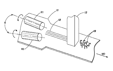
fastening elements
on the otherwise loop substrate. Such a substrate with loops provided thereon
may include
any suitable material, such as a nonwoven, woven, textile, polymer, foam,
fibrous material,
other suitable materials, or combinations thereof.
[00661 As noted above, a self-engaging fastener strip may be formed by
selective
patterning of hooks or hook fields directly onto a suitable elastomeric loop
substrate. For
example, hook fields may be patterned on a loop substrate in any suitable
configuration. In
some embodiments, hooks and loops may be formed in a checkerboard, striped
and/or other
patterned arrangement, which may allow for hooks and loops to be suitably
available for
mutual engagement when surfaces are mated face to face. That is, patterned
surfaces with
both hook and loop fields may be appropriately mated when brought together
into mutual
contact.
[0067] In some embodiments, to achieve a strong attachment, it may be
preferable for
the surface of a touch fastener to include numerous leading and trailing edges
where, when
fastening products are peeled from one another, the leading edge is the edge
of a field of
fastening elements that is first removed, and the trailing edge is the last
part of the field of
fastening elements that is removed. It has been observed that when attaching
hook and loop
touch fasteners to one another, there tends to be improved engagement between
fasteners
along leading and trailing edges of a hook field. That is, the more leading
and trailing edges
there are between touch fasteners, the more difficult it may be to separate
them from one
another. Without wishing to be bound by theory, this may be due, at least in
part, to the
increased quantity of fastener elements engaged or readily engageable ¨ that
is, the fastener
elements are not shielded by adjacent fastener elements and may be able to
penetrate the
mating material more easily. Fastening surfaces having more surface area may
exhibit a
CA 02980074 2017-09-15
WO 2016/149243 PCT/US2016/022420
greater ability to mutually engage as opposed to fastening surfaces having
comparatively less
surface area.
[0068] Hence, the attachment between one surface that is fonned entirely
of hook
elements and another surface formed entirely of loop elements may not be as
strong as the
attachment between two complementary surfaces each foimed of a striped,
checkerboard
and/or other suitable arrangement of hook and loop fields. Or, in some
embodiments, it may
be preferable to form an attachment between one surface formed of a striped or
grid-like
pattern of hook elements and another surface formed entirely of loop elements,
or vice versa.
By forming the fastener element in discrete patterns, such as rows/columns
and/or patches,
more leading and trailing edges may be made available for engagement between
fastening
surfaces, thus, providing a more secure attachment.
[0069] Fig. 2A shows an illustrative embodiment of a fastening surface
having a
striped pattern of hooks 19 formed directly on an elastomeric non-woven
substrate 21. Fig.
2A further shows the striped fields of hooks 19 separated from one another by
edges 40a,
40b, with virgin substrate material located between stripes. As discussed
above, these edges
40a, 40b may serve as leading and trailing edges for enhancing attachment
between fastening
surfaces. For example, the fastening surface having the striped pattern of
hooks 19 feinted
from the elastomeric substrate 21 may form a relatively stronger attachment to
a surface
entirely of loops as compared to an attachment between a fastening surface
fonned entirely of
hooks 19 and a surface entirely of loops.
[0070] In some cases, material processed to form hooks or other fastening
elements
may be formed to be relatively stiffer in comparison to the substrate material
that has not yet
been processed. That is, processed substrate material may be stiffer than non-
processed
substrate material. Thus, the remaining stripes of virgin substrate material
may desirably
provide an added degree of flexibility for the overall product.
[0071] In one embodiment of a fastening surface, fastening elements are
formed
according to a patterned arrangement. In this embodiment, patches of hooks are
formed on
an elastomeric non-woven substrate material. In various embodiments, where
elements are
formed as an individual element and/or a patch of elements, the portion of the
elastomeric
non-woven material surrounding the element(s) may remain unaltered. This may,
for
example, allow for the formation of intermittent patches of hooks or other
fastening elements
CA 02980074 2017-09-15
WO 2016/149243 PCT/US2016/022420
21
directly on to the substrate material (e.g., material forming a diaper tab),
optionally leaving a
relatively bald perimeter area (e.g., of elastomeric non-woven material)
around the hook
field. This bald or unaltered perimeter may provide a relatively soft and low
stiffness
material which, in some cases, may limit marking and/or irritation for a user
(e.g., wearer of a
diaper, garment, etc.) of the fastening product.
[0072] It can be appreciated that fastening elements may be patterned on
to a
substrate according to any suitable arrangement. Such patterns may be located
intermittently
along the surface of the substrate and/or may include, for example, lines,
stripes, circles, arcs,
ellipses, ovals, squares, rectangles, angled lines, patches, logos, etc.
[00731 In some embodiments, it may be desirable to reinforce various
regions of the
substrate. For instance, using material from the substrate to form the
fastening elements may
result in a reduction in overall strength, stiffness, etc. of the substrate.
Accordingly, a
reinforcing structure may be provided on the substrate, for strengthening
and/or stiffening
thereof. For example, ultrasonic energy may be used to modify the substrate
material
adjacent to and/or between elements or patches of elements to form such
reinforcing
structures. Fig. 2B shows reinforcing elements 50 provided as ribs or ridges
that are
vibrationally formed from the substrate 21. Such reinforcing elements 50 may
be formed
adjacent to or as part of certain fastening elements to provide support
thereto and/or for the
substrate as a whole. The reinforcing elements 50 may be formed so as to be
connected to
the sides of fastener elements 19 and/or the fronts of the fastener elements
in such a manner
as to provide side support and/or front/back support to the fastener element
and may serve to
reinforce fastener elements from various directional forces. Furthermore,
depressing the
substrate in the region adjacent the berms 50 allows that material to be
utilized for the
formation of the fastener element. That is, without the corresponding
depression, there may
be insufficient volume of material necessary to form a complete fastening
element. The
reinforcing elements may be compacted to a greater or lesser extent than the
compaction of
the fastening elements.
[0074] In one embodiment, as shown in Fig. 2C, the substrate 21 may be
formed with
berms 50 placed in a zig-zag pattern. When configured in a zigzag or other
compliant
pattern, the resulting structure may serve to limit stretch of the substrate
(in the direction of
the arrows) when used on elastomeric substrates when a stretching force is
applied thereto.
CA 02980074 2017-09-15
WO 2016/149243 PCT/US2016/022420
22
[0075] As described herein, rather than forming a single type of
fastening element on
an entire surface of a fastening product or sheet, it may be preferable to
form patterns of
different types of fastening elements along the surface. In accordance with
aspects of the
present disclosure, fields of hooks may be formed on a substrate previously
having loops on
the entirety of the surface. For example, Fig. 2D shows an illustrative
embodiment of a
fastening surface having a striped pattern of alternating fields of hooks 19
and loops 30, with
the fields of loops 30 lofted over the fields of hooks 19. By virtue of the
striped pattern, the
fields of hooks 19 and loops 30 include a number of leading and trailing
edges. In various
embodiments, including that shown in Fig. 2D, the hooks 19 may be formed on a
substrate
previously having loops 30 on the entirety of the surface. That is, in
accordance with aspects
of the present disclosure, loops on a substrate may effectively be changed
into hooks. For
instance, a vibrating source such as an ultrasonic transducer/horn may be
placed into contact
with a region of loops, melting and/or softening that portion of the
substrate. A suitable mold
having appropriately shaped cavities may be applied to the softened portion of
the substrate,
forming hooks directly on regions of the substrate that had previously been
loops where the
loop material or loop structure itself is forced into mold cavities to form
fastening elements.
[00761 Figs. 3A-3B depict an embodiment of a fastening surface that may
be suitable
for use with infant diapers. In this embodiment, the product 100 (e.g., diaper
tab material)
may be an elastomeric fibrous non-woven material having a side tab 102 on
which
appropriate touch fasteners are directly formed. A user may press the touch
fasteners on the
side tab 102 against an appropriate fastening surface (e.g., a landing field
on the diaper, or
other portions of the diaper, such as the shell of the diaper, or other areas
having suitable
mating features), for example, in securing a diaper to an infant, or holding
portions of a
garment together. In some embodiments, such tabs 102 may be constructed with a
piece of
extensible material (e.g., elastomer) that allows the tab to stretch and flex
when attached
and/or upon movement of the wearer (e.g., infant, child). In some embodiments,
a separate
fastening material having the fastening elements is affixed to the side tab
102, as is often the
case for diapers. Though, in accordance with aspects of the present
disclosure, the fastening
elements may be formed directly on the side tab 102. For example, a vibrating
source and
mold may be applied directly to the elastomeric fibrous non-woven material
provided for the
side tab 102 so that the side tab itself has the fastening elements formed
integrally thereon.
CA 02980074 2017-09-15
WO 2016/149243 PCT/US2016/022420
23
Fig. 3B is a close-up view of a portion of the tab shown in Fig. 3A, more
readily showing a
striped fields of hooks 19 separated from one another by edges 40a, 40b, with
virgin substrate
material 21 located between stripes. As discussed above, these edges 40a, 40b
may serve as
leading and trailing edges for enhancing attachment between fastening
surfaces.
[0077] Fastening materials may be manufactured according to any suitable
process.
In accordance with aspects of the present disclosure, such manufacturing
processes may
employ ultrasonic and/or vibrational energy to locally soften or otherwise
operate on the
material from which fastening elements (e.g., projections, protrusions, pins,
hooks,
mushroom heads, loops, etc.) are formed. Fig. 4, discussed further below,
shows an
exemplary embodiment where a forming substrate 11 (e.g., made up of
elastomeric material,
non-woven material, woven material, thermoplastic material, etc.) is
positioned and passed
between a vibrating source 13 (e.g., ultrasonic source) and a mold 15 (e.g.,
rotating mold
roll). In this embodiment, the mold 15 includes multiple hook-shaped or other
suitably
shaped cavities 17 along the outer periphery from which appropriately shaped
hooks, or other
fastening elements, may be formed.
[0078] It can be appreciated that fastening materials may be manufactured
according
to appropriate processes using different configurations. In some embodiments,
the molding
roll may itself include a vibrating source that provides appropriate energy
for softening
and/or forming the fastening elements. In some embodiments, a molding roll is
not required,
as the fastening materials may be fanned along a conveyor, stamping
configuration and/or
according to another suitable manufacturing arrangement. In some embodiments,
the source
of vibration (e.g., ultrasonic vibration) may be provided by a vibrating horn.
The horn may
have a curved surface that corresponds to the curvature of the molding roll.
In some
embodiments, multiple ultrasonic horns may be employed.
[0079] During operation, the vibrating source 13 may be positioned in
relatively close
proximity to, yet spaced from, the outer surface of the rotating molding roll
15. The vibrating
source 13 may come into contact with the forming substrate 11 as it passes
through. In
various embodiments, the vibrating source 13 may include, but is not limited
to, for example,
an ultrasonic horn. Such horns may be made from any appropriate material
(e.g., metals such
as aluminum or titanium, piezoelectric materials) and are sold in the United
States by
companies such as Branson Ultrasonics, Dukane or Sonitek, and in Europe by a
company
CA 02980074 2017-09-15
WO 2016/149243 PCT/US2016/022420
24
such as Mecasonics. The vibrating source 13 may vibrated at any suitable range
of
frequencies, such as between about 50 Hz to about 50 kHz, or alternatively as
desirable.
Other sources of vibration energy may be utilized, including but not limited
to, a rotating
eccentric roller, high pressure sound waves or other mechanical and/or
electromechanical or
acoustical forms of vibration energy. Such energy may therefore be transferred
to a substrate
and assist in the foimation of fastening elements described herein.
[00801 As shown in Fig. 4, the fastening product may be formed by rotary
forming.
Accordingly, when coming into contact with the molding roll 15 and vibrating
source 13, the
forming substrate 11 may be appropriately softened by vibrational energy.
Hence, a softened
portion of the substrate may be caused to enter into cavities 17 of the
molding roll, forming
hook-shaped or other suitably shaped elements or projections 19 on the front
surface of the
film or sheet 21 as the roll turns. The forming substrate 11 may include, but
not be limited to,
a film, sheet, web, composite, laminate or other form, or may be portions of a
film, sheet,
web, laminate, thermoplastic, non-thennoplastic, woven, non-woven, fibrous
and/or
elastomeric material, which may be used as forming material for individual
fastening tabs, for
instance on a disposable infant diaper, or which may be used as forming
material for the
disposable infant diaper itself (e.g., the shell of the diaper). In the
depicted embodiment, the
substrate is a two-layer laminate, though the disclosure is not limited in
this regard.
[0081] In some embodiments, a suitable amount of force/pressure may be
applied to
the substrate 11 to assist in causing a sufficient amount of the substrate
material to enter and
fill-out the cavities 17.
[00821 In some embodiments, the formed substrate 21 (that is, the
substrate having
the fastener elements now formed thereon) may function as a carrying strip for
the fastener
elements (e.g., hooks) 19.
[0083] In some embodiments, the material of the initial substrate
11(i.e., before
fastener formation) is the same as the material of the formed substrate 21. In
other
embodiments, such as when a laminating material or powder is introduced during
the forming
of the fasteners, the formed substrate 21 may have a different material
composition that the
initial substrate 11.
[0084] As discussed above, the substrate may be heated to a temperature
around or
just below its melting point prior to or during the vibrational forming of
fastening elements.
CA 02980074 2017-09-15
WO 2016/149243 PCT/US2016/022420
In some embodiments, the temperature may be raised to approximately the glass
transition
temperature of the substrate material (e.g., glass transition temperature of
polyethylene,
polyurethane, nylon, polypropylene, polyimide, polyamide, rubber,
polyisoprene,
polybutadiene, polyneoprene, etc.). For instance, the temperature at around or
the substrate
during processing may be raised to greater than 30 C, greater than 40 C,
greater than 50 C,
greater than 60 C, greater than 70 C, greater than 80 C, greater than 90
C, or greater than
100 C; or less than 100 C. less than 90 C, less than 80 C, less than 70
C, less than 60 C,
less than 50 C, less than 40 C, or less than 30 C. Combinations of the
above noted ranges
may be possible, or temperature outside of these ranges. As a result of such
heating, the
overall efficiency of production may be enhanced. For example, heating of the
substrate may
result in an increase in the line speed of manufacture and/or require less
vibrational energy
than would otherwise be needed for adequate material to enter the cavities and
ultimately
form the fastening elements.
[0085] Fig. 4 further shows heating devices 25, 26 used to heat the
forming substrate
11 as it moves toward the vibrating source 13 and the mold 15. As shown, the
heating device
25 provides convective and/or radiative thermal energy toward the forming
substrate 11. In
addition or in the alternative, a heating device 26 is provided as a heater
through which the
substrate 11 travels prior to processing between the vibrating source 13 and
the mold 15.
Any suitable heating device(s) may be used, such as for example, a heat lamp,
filament, hot
air blower, oven, or any other suitable unit for applying thermal energy. It
can be appreciated
that the substrate may be heated by any suitable method. As noted above, for
some
embodiments, the substrate may be heated before, during and/or after forming
via the
vibrating source and mold.
[0086] As described herein, fabrication of the fastening elements may
require a
sufficient amount of substrate material; otherwise as portions of the
substrate material are
softened, there may be difficulty in fully filling cavities provided by the
mold, for suitably
forming the fastener elements. Though, for some applications (e.g., diapers),
it may be
preferable for the substrate material to be suitably light-weight (e.g., spun-
melt-spun material
used by diaper manufacturers may have a mass ranging between 40-60 g/m2).
[0087] Thus, in attempting to stay within a certain weight and/or mass,
while also
leaving a sufficient amount of material as a backing, it may be common for
fastening
CA 02980074 2017-09-15
WO 2016/149243 PCT/US2016/022420
26
elements to be only partially formed. To ensure that enough substrate material
is available
for adequate forming of the fastening elements, it may be possible to reduce
the cavity
volume, form smaller fastening elements, and/or decrease the density/quantity
of cavities
over a certain area, resulting in the formation of smaller sized and/or a
smaller number of
fastening elements.
[0088] Alternatively, in accordance with aspects of the present
disclosure, as
discussed above, it may be preferable to thicken or otherwise increase the
available amount
of material where touch fasteners are formed. In one embodiment, the substrate
may be pre-
formed such that there exists additional material (i.e., bulking up of the
material) at the
location where the fastener element is to be formed. Thus, a first area of the
substrate is
gathered to a second area of the substrate and fastener elements are formed in
the second
area. The second area may be smaller than the first area. Figs. 5A-5D
illustrate various
embodiments where the amount of local substrate material available for forming
the fastening
elements is increased using an otherwise constant thickness material. In some
embodiments,
such gathering may involve collecting a portion of the substrate material
prior to formation of
the fastening elements (e.g., passing of the substrate forming material
between a mold and
ultrasonic horn). The thickening or gathering may be formed intermittently on
the substrate,
as the present disclosure is not limited in this regard.
[0089] For instance, Fig. 5A shows an embodiment where substrate material
ha is
gathered so as to form pleats 12a, providing an added volume of material under
the vibrating
source 13 for forming of fastening elements that are suitably sized. As noted
above, the
pleats 12a along the substrate may have any suitable shape or configuration
(e.g., waves,
corrugations, etc.), depending on the amount of material desired.
[0090] Fig. 5B depicts another embodiment where the substrate material 1
lb is
gathered so as to form an overlapping region 12b, which also provides
additional material for
forming of the fastening elements. In some embodiments, similar to that with
respect to the
pleats, a forming device may be used to fold appropriate portions of the
substrate over itself,
providing the regions of added material.
[0091] Or, for certain embodiments such as that shown in Fig. 5C, a
supplemental
material 10 such as a film, nonwoven and/or other material may be added to the
substrate
material 11c. That is, an additional product and/or layering may be suitably
placed on the
CA 02980074 2017-09-15
WO 2016/149243
PCT/US2016/022420
27
substrate material 11c at a location 12c for subsequent processing.
Accordingly, the
fastening elements may be formed when the portion of the substrate material
11c on which
the supplemental material 10 is added is placed in appropriate contact with
the vibrating
source 13.
[0092] In one embodiment, the substrate 11 may be slit during the
formation process
before the material enters the nip area of the ultrasonic source. The slit
substrate is then
overlapped onto each other at the region 12d where the fastener elements are
to be formed, as
shown in Fig. 5D.
[0093] In various embodiments, such as that shown in Figs. 6A-6E, a
forming device
2 may be used to process the substrate 11 so as to gather material together,
providing an
adequate amount for fastening elements to be fully formed. As shown, in this
embodiment,
the substrate 11 is fed into the forming device 2, resulting in the formation
of pleats 12
extending along the cross-machine direction CD of the substrate. Gathering of
the substrate
material in the cross-machine direction CD may allow for the substrate
material to be easily
fed along a line toward a vibrating source 13 for formation of the fastening
elements, as
shown in Fig. 6A. Though, it can be appreciated that the pleats 12 may also be
formed in the
machine direction MD, if desired.
[0094] The pleated portion 12 of the substrate 11 then moves into contact
with the
vibrating source 13, for forming the fastening elements. In some embodiments,
the vibrating
source 13 may itself have a surface that complements the morphology of the
gathered
substrate material. For example, the vibrating source 13 may have a relatively
wavy surface
for receiving the pleated or otherwise gathered portion 12 of the substrate
11.
[0095] The forming device 2 may gather material in any suitable manner.
In some
embodiments, as the substrate 11 is fed through the device 2, the substrate
material is
channeled along a corrugated boss, which forms the pleats thereon. In some
cases, the
substrate material may be funneled or pushed by other machine components
toward and/or
against the corrugated boss. In some cases, the substrate material is heated
as it is gathered,
so as to enhance pliability and/or flowability of the material. It can be
appreciated that other
methods and components may be used to gather the substrate material together
in an
appropriate manner, to enhanced manufacturability of the fastening elements.
For example,
CA 02980074 2017-09-15
WO 2016/149243 PCT/US2016/022420
28
as noted above, the device 2 may fold portions of the substrate 11 over itself
to provide an
adequate amount of material moving toward ultrasonic formation.
[0096] In one embodiment, as shown in Figs 6C and 6D, the device 2
includes upper
forming bar 60 and lower forming bar 62, each with complementary shaped
grooves that
cause the substrate material to gather in the pleated fashion as shown. The
upper and lower
forming bars may be spaced apart a fixed or adjustable distance. As shown in
Fig. 62, the
leading edge of the device 2 (that is, the material entrance into the device)
is relatively flat
corresponding to the flat shape of the substrate material. On the exit or
trailing edge of the
device 2, the upper and lower bars 60, 62 are formed with a corrugated or
pleated surface 66
that cause the substrate to gather into pleats. Though not shown, the mating
faces of the
upper and lower forming bars are formed with a flat funnel shaped entrance
that transitions to
the pleated section. Fig. 6H shows a schematic representation of the substrate
11 having the
gathered or pleated portion 12 after having been subject to a gathering
process. The pleats
may be tight or loose, as desired. Accordingly, as shown in Fig. 6E, the
device 2 may include
a more tightly spaced pleated surface 68.
[0097] Other arrangements for creating pleats may be employed, as the
present
disclosure is not limited in this regard. For example, as shown in Fig. 6F,
counter rotating
rolls R1 and R2 that rotate about an axis that is located along (or at a
slight angle 0 such that
one or both roll axes is/are offset relative to) the machine direction MD may
be used. As the
substrate 11 is fed along in the MD, the counter rotating rolls cause the
material to gather at
the location between the rolls. In one embodiment, the rolls R1 and/or R2
include needles or
a roughened surface to aid in gripping and gathering the material. This
gathered material 12
is then fed into the nip below the vibrating source 13 for further processing
to produce the
field of fastening elements 19. Other gathering rolls may be employed as the
present
disclosure is not limited in this regard. For example, one or more rolls
rotating in a direction
generally perpendicular to the MD. The roll or rolls includes helically formed
ridges, with
one roll having a left-handed helix and the other roll having a right-handed
helix. These
oppositely formed helices are positioned such that the material is urged
toward the center to
gather the material. Of course, a single roll, such as roll R shown in Fig. 6G
may be
employed having both the left-handed helix Ti and right-handed helix T2. It
should be
CA 02980074 2017-09-15
WO 2016/149243 PCT/US2016/022420
29
appreciated that the rolls of Fig. 6F and 6G are shown schematically and would
be coupled to
axles and suitable drive arrangements.
[0098] In another aspect of the present disclosure, it may be preferable
to enhance the
efficiency with which ultrasonic energy is applied. Because fastening
elements, such as
hooks and loops, take up only a discrete amount of space, it may be beneficial
to control the
amount of ultrasonic energy applied to the forming substrate material. That
is, it might not be
necessary for vibrational energy to be applied to the entire surface of the
forming substrate
material. For instance, the application of vibrational energy may be localized
such that only
areas of the forming substrate material that are required for producing
fastening elements
may be subject to vibrational energy. Hence, the surface(s) of the mold and/or
vibrating
source may be tailored such that vibrational energy is only applied to the
necessary locations
for producing fastening elements.
[0099] In some embodiments, the maximum line speed of production using
ultrasonics for producing fastening elements may be limited by the available
power of
existing ultrasonic generators. Hence, production throughput may be improved
by tailoring
the application of ultrasonic energy, for example, by patterning the molding
tool and/or
vibrating source such that a suitable level of ultrasonic energy is applied
only to the portions
of substrate material that require it. For example, the topographical surface
of the mold and
cavities of the mold are designed for ultrasonic energy to be applied to
certain areas in the
immediate vicinity of the cavities. That is, there is little to no need to
compress, heat and/or
ultrasonically treat areas that are not in the immediate vicinity of a cavity
unless it is
anticipated that the material in those areas will be urged into a cavity.
[00100] However, it should be appreciated that the present disclosure is
not limited in
this regard. For example, in some embodiments, the substrate material not
intended to be
utilized for the formation of fastening elements may otherwise be processed
via the ultrasonic
energy so as to form a berm or other reinforcement element or other desirable
structure. In
such an embodiment, it may be desirable to have some level of compression of
the substrate
in these regions. In another example, islands or fields of fastening elements
may be
produced on the substrate, such as on a diaper side tab, with the region
around the fastening
elements being slightly compressed (or not compressed at all) to create a bald
periphery.
Further, when a second material is introduced into the nip area and islands of
fastening
CA 02980074 2017-09-15
WO 2016/149243 PCT/US2016/022420
elements are formed, it may be desirable to "stake" or partially bond these
two layers in areas
where there are no fastening elements. In other words, if two layers of
nonwoven material
were being formed with intermittent patches of hooks elements, those portions
of the
resultant substrate between these patches would include two layers of nonwoven
material that
are not otherwise bonded together in any way. It may be desirable to bond
these two layers
together sufficiently to make them appear as one layer without stiffening the
bonded region.
[00101] Figs. 7A-7B show illustrative embodiments where the vibrating
source 13 or
the mold 15 is designed so as to include contact regions for compressing the
substrate
material toward the ultrasonic energy during forming of the fastening
elements, and recesses
which are not intended to come into contact with the substrate material. It
should be
appreciated that the recesses may be sized so as not to contact the substrate
at all or may
contact the substrate so as to compress the substrate to a lesser extent than
the material that
will be urged into the fastener cavities or other feature foi ming cavity
(e.g., beini or
reinforcement cavity). The contact regions include cavities into which the
softened substrate
material flows when exposed to vibration energy, heat and/or other forming
conditions.
[00102] For the example shown in Fig. 7A, the vibrating source 13 has
contact regions
5 for operating on and applying ultrasonic energy to the forming substrate
material, and
recesses 7 separating the contact regions 5. The contact regions 5 have
cavities 17 within
which material is formed into fastening elements (e.g., hooks). When the
substrate material
is suitably compressed or otherwise placed between the vibrating source 13 and
a plate (not
shown in this figure), the portion of the foiniing substrate material that is
pressed against the
surface of the contact regions 5 is softened so as to deform and/or flow into
the cavities 17,
for forming of the appropriate fastening elements. During processing, the
recesses 7 pass
over areas of the forming substrate material where the fastening elements are
not intended to
be formed. In this example, the vibrating source 13 may be used as a stamp
that, along with a
suitable plate, sandwiches the substrate material therebetween. Though, it can
be appreciated
that a suitable mold may be used along with the vibrating source 13.
[00103] In the example of Fig. 7B, similar to that shown in Fig. 4, the
mold 15 is
provided as a roll on which a sheet of substrate material may move along.
Accordingly,
substrate material that is compressed between the contact regions 6 of the
mold 15 and the
vibrating source is caused to deform into the cavities 17, resulting in
forming of the fastening
CA 02980074 2017-09-15
WO 2016/149243 PCT/US2016/022420
31
elements. Also, the recesses 8 are aligned with those regions of the substrate
material where
the fastening elements are not intended to be formed. While a vibrating source
is not shown
in Fig. 7B, it can be appreciated that any suitable vibrating source may be
used along with the
mold 15. Alternatively, the mold 15 may act as the vibrating source.
[00104] In such embodiments, the vibration energy is directed or
concentrated toward
the portion(s) of the substrate material from which fastening elements are to
be formed and
the immediate surroundings. As a result, there is little to no waste of
vibration energy on
other portions of the substrate material which are not intended to be formed
as fastening
elements.
[00105] It can be appreciated that contact regions and recesses of molds
and/or
vibrating sources may have any suitable characteristics and dimensions. The
contact regions
may be large enough to press against and cause an adequate amount of substrate
material to
fill into respective cavities. For instance, if the contact regions are too
small, then an
insufficient amount of substrate material may be operated upon for filling of
the cavities. On
the other hand, larger contact regions and smaller recesses might not be
necessary for
formation of the fastening elements, and could lead to manufacturing
inefficiencies where
ultrasonic energy is unnecessarily applied to certain portions of the
substrate material.
Further, the recesses may be structured to further limit the amount of
vibration energy
imparted to the substrate material within or adjacent the recess.
[00106] The contact regions and/or recesses may have any suitable
combination of
structural features, such as ridges, fillets, rounds, bevels and/or other
oriented features that
may serve to guide material towards respective cavities, increasing the
available amount of
material for production. These structural features may also serve to provide
support to
individual fastening element enhancing their ability to resist loads applied
from various
directions. For example, the area around the formed fastening element may have
been
weakened or thinned during the forming process and thus the fastening element
itself may not
adequately resist the forces applied to it to hold onto the mating fasting
element (which may
occur due to the shear load placed on the fastening element). By foitning
structural
enhancements such as reinforcement members, berms, ridges, etc., that may
serve to link
adjacent fastening elements, the fastening elements may better resists the
shear loads applied
to it. In one embodiment, as shown in Fig. 2B, the beilits 50 are formed so as
to effectively
CA 02980074 2017-09-15
WO 2016/149243 PCT/US2016/022420
32
link the fastening elements 19 side to side and front to back. Contact regions
and recesses of
the mold and/or vibrating source may also be arranged according to any
suitable pattern. For
instance, contact regions and recesses may be arranged for the formation of a
small number
of fastening elements (e.g., single cavity, few cavities within a contact
region) and/or for
larger numbers or patches of fastening elements (e.g., numerous cavities
within a contact
region). This may include the formation of single hook elements foliated along
various
positions on the substrate material. These single hook elements may be formed
as individual
elements or may be fotined as a patch of elements separated from one another,
or may be
alternatively formed on an entire surface of a substrate. As an example, for
the formation of
relatively large patches of hooks, a mold and/or vibrating source may have
contact regions
separated by recesses where each of the contact regions may have several
cavities.
[00107] As also described herein, supplemental materials may be provided
to the
substrate material and/or cavities before, during and/or after fastening
elements are formed.
In some embodiments, such supplemental material(s) may serve as an adhesive,
binder and/or
stiffening agent, for producing mechanically strong, durable, flexible and/or
resilient
fastening elements. In some embodiments, additional material(s) (e.g., corn
starch, talc,
barium (which may aid is x-ray imaging if the end-product is used in medical
applications),
gypsum, ceramic, biodegradable, anti-microbial, ferrous or non-ferrous
materials,
magnetically attractive materials, RE excitable material (which allows the
substrate to be
heated using RF energy)) may be introduced before, during and/or after
formation of the
fastening elements. Such materials may be in powdered or sheet/film form. The
additional
material(s) may be applied to a surface (e.g., laminated, coated, dusted,
etc.) and/or
impregnated (e.g., saturated, mixed, etc.) with the substrate material, for
beneficially altering
certain characteristics of the fastening elements. In some embodiments, the
additional
material(s) may be provided to the substrate material according to a pattern
where a fraction
of the fastening elements on a product exhibit certain qualities (e.g.,
stiffer, harder, more
resilient, etc.) and other fastening elements on the product exhibit other
qualities (e.g., softer,
more flexible, etc.). For example, as shown in Figs. 8A-8B, additional
materials may be
laminated and/or embedded with the substrate material.
[00108] Figs. 8A-8B show illustrative embodiments of multilayered
arrangements
where one or more layers are laminated and/or embedded with the substrate
material 21, for
CA 02980074 2017-09-15
WO 2016/149243 PCT/US2016/022420
33
forming a projection 19, or fastening element (e.g., hook, stem, etc.). In
Fig. 8A, the second
material 121 has been joined or otherwise positioned adjacent to the substrate
material 21 and
through processing according to the present disclosure, the projection 19 is
formed. As the
projection 19 is formed, a portion 122 of the second material 121 may extend
into the body or
stem 19A of the projection 19, which may provide enhanced properties to the
projection. For
example, portion 122, which may be formed from substrate material 121 may have
a different
Shore Hardness value than the Shore Hardness value that is associated with
substrate material
21.
[00109] In some embodiments, the substrate 21 includes an elastomeric
material, a
portion of which is formed into the projection 19 or fastening element. As
shown in Fig. 8A,
a portion 122 of the second material 121 protrudes into the body 19a of the
projection 19. In
some embodiments, the viscosity, melting and/or glass transition temperature
of the second
material 121 may be similar to that of the substrate material 21, for example,
to allow for a
strong attachment or adherence between the substrate material 21 and second
material 121.
In various embodiments, it may be preferable for at least a portion of the
second material 121
to be drawn up into the body 19a of the projection 19. In some cases, the
second material
121 may include fibers, stiffeners, additives and/or other materials, which
may exhibit
characteristics that may be desirably incorporated into the projection 19. In
some
embodiments, both the substrate 21 and the second material 121 may include an
elastomeric
material.
[00110] Fig. 8B shows another embodiment of a multilayered laminate
arrangement.
In this example, a second material 121 is embedded within the substrate 21.
This embedded
material 121 may be selected according to any suitable desired characteristics
and, for
example, may include non-woven materials, woven materials, open foam
materials,
polymers, elastomers, other materials, or combinations thereof. In contrast
with the example
of Fig. 8A, the material 121 forms the projection 19 or fastening element. The
substrate
material 21 may be a fibrous non-woven material and the second material 121
may be an
elastomeric film embedded within the non-woven material 21. The elastomeric
film may
provide an added degree of stretch and elasticity to the product and, as noted
above, may be
used as material in forming the protrusions 19.
CA 02980074 2017-09-15
WO 2016/149243 PCT/US2016/022420
34
[00M] The elastomeric film may be embedded within the non-woven material
by any
suitable method. In some cases, the elastomeric film may be introduced during
the
vibrational forming process. The elastomeric film may have melt and glass
transition
properties that differ from the non-woven material and, hence, may be softened
and forced
through fibrous pores of the non-woven component and into the hook cavities,
resulting in
the formation of elastomeric hooks on the surface of the substrate, with a non-
woven material
left predominately in the plane of the substrate surrounding the elastomeric
projections 19.
Accordingly, as shown in Fig. 8B, the second material 121 (e.g., elastomeric
material) may
form the projection 19 (e.g., hook) rather than the substrate material 21
(e.g., fibrous non-
woven material). Though, it can be appreciated that in such an embodiment, the
substrate
material 21 and the second material 121 may include any suitable composition.
For example,
the substrate material 21 may include an elastomeric material and/or the
second material 121
may include a non-woven material.
[00112] In some embodiments, the second material 121 may be a polymer film
having
a lower melt temperature than the non-woven material of the substrate 21.
Similar to that
with respect to the elastomeric material, the polymer film may be introduced
between the
vibration source and nonwoven substrate and heated so as to be softened, and
then forced
through the fibrous pores of the non-woven material and into the hook
cavities, for forming
the projections 19. Hence, the non-woven material may be left predominately in
the plane of
the substrate surrounding the polymeric projections 19. Accordingly, when
producing a
fastening product from multilayered laminate substrates, aspects according to
the present
disclosure make it possible to selectively form fastening elements (e.g.,
hooks) from one or
more of the layered materials, for example, based on melt properties of a
particular material.
[00113] In one experiment conducted by the inventor, the inventor
introduced
aluminum foil between a polymer film and the mold roll during application of
ultrasonic
energy. The polymer film burst through the foil at each cavity and allowed the
polymer to fill
the cavities. This produced a touch fastener strip that was mostly comprised
of polymer but
had a surface layer of aluminum on the hook side surface. The foil exhibited a
slight flaring
into the cavities as the foil was apparently stretched prior to or immediately
after bursting.
The foil layer could add reflectivity to the touch fastener strip. Other metal
foils or retro-
reflective foils may be used.
CA 02980074 2017-09-15
WO 2016/149243
PCT/US2016/022420
[00114] A layer of paper or other cellulosic material may be substituted
for the foil if
desired. This may allow for the production of a touch fastener strip with a
decorative or
functional top layer. The layer could be a preprinted paper containing images
or logos or
instructions, etc. This layer may be introduced with a single layer of polymer
or may be
introduced with other materials as well. For example, a layer of non-woven
material, a
polymer film and a layer of preprinted paper may be introduced between the
mold roll and
vibration source with the paper positioned on the mold roll side. Hook
elements may then be
formed after bursting through the paper and the polymer film would be
simultaneously
attached to the nonwoven material. This would allow logos or images to be
created on the
hook surface of a diaper tab. Cartoon characters or other designs may be
utilized.
[00115] It should be appreciated that the overlying layer may not be burst
through and
instead the underlying material may simply extend through the overlying layer.
In one
embodiment, this may occur when the overlying layer is folmed as a porous
layer such that
the underlying material may simply extend through the pores of the overlying
layer. Porous
layers may be formed by forming holes in the layer or simply from a fibrous
nature of the
material.
[00116] It may be also desirable to print onto the substrate utilizing the
mold roll. For
example, prior to forming the fastening elements, the ink applied to or
through the mold roll
would then transfer to the face of the hook side of the substrate.
[00117] In one embodiment, fastener elements may be formed on human or
animal
tissue insitu by employing controlled vibration energy. The fastening elements
would be
mated with adjacent tissue via penetration into the adjacent tissue. The mated
structure
would act as a temporary closure (e.g., wound closure) and ultimately be
absorbed into the
body. In addition, or alternatively, a wound closure device may be formed by
folining
fastening elements on a collagen or other bio-absorbable material by employing
vibration
energy, which could be mated with adjacent tissue.
[00118] As described herein, fastening products may employ a suitable
multilayered
laminate arrangement. For some embodiments, it may be desirable to control the
ability of a
material to stretch. For instance, substantially extensible or non-extensible
materials may be
laminated to or otherwise incorporated with the substrate and/or materials
(e.g., elastomeric,
polymeric materials) of the fastening product before, during and/or after
formation of the
CA 02980074 2017-09-15
WO 2016/149243
PCT/US2016/022420
36
fastener elements. When a substantially non-extensible or relatively stiff
material is
laminated to or embedded within a substrate incorporating an elastomeric
material, the
overall fastening product may be more limited in extensibility. It can be
appreciated that the
additional stiff material may extend over a portion or the entirety of the
surface of the
fastening sheet. The additional stiff material may include any suitable form,
for example,
such a material may be a sheet, film, wire, strips, etc. In some cases, it may
be preferable to
limit the extent to which the fastening product is able to stretch, for
example, so that the
product does not abruptly snap back into position, reduce the likelihood for
the product to be
damaged, etc.
[00119] As discussed above, the amount of stretching of the substrate may
be limited,
for example, via a tether, non-extensible strip, and/or other material that
exhibits a relatively
high stiffness when the substrate is subject to a certain level of extension.
Such a tether
and/or strip may be incorporated into the substrate via any suitable method,
for example,
during formation of the fastener elements, lamination and/or another
appropriate method.
[00120] Figs. 9A-9B depict an example of a substrate having a stiff,
generally non-
extensible material laminated with more stretchable material. In this
embodiment, the
fastening elements 19 extend from the substrate 21, which is formed of a
stretchable
elastomer. An additional layer 130, formed of a non-extensible material (e.g.,
polymer,
thermoplastic, non-extensible rubber, etc.), is laminated to the substrate 21
(such lamination
occurring prior to or during the formation process). Fig. 9A shows the
fastening product in a
retracted position where it can be stretched, folded and/or bent in any
suitable direction. Fig.
9B shows the product in an extended position where the components are
stretched out. Here,
when the stretched product extends to a certain point, the additional layer
130 provides
resistance to further stretching. Accordingly, the additional layer 130 may
suitably prevent
excessive stretching of the product.
[00121] It is also possible to modify or enhance the performance of an
existing loop or
loop-like structure using ultrasonic energy applied to the substrate either
while forming the
fastener elements or before or afterward. For example, when applied to a non-
woven
substrate that may be marginal as a mating fastener (e.g., loop) material, a
honeycomb
surface pattern on the mold roll, located in regions of the mold roll where
there are no
fastener element (e.g.,) hook cavities, could serve to selectively compress
and bond a non-
CA 02980074 2017-09-15
WO 2016/149243 PCT/US2016/022420
37
woven substrate in such a fashion so as to create dots or patches of mating
fastener that are
more functional (e.g., by compressing the perimeter, a raised pillow of
substrate material is
formed, with such material being more readily snared by hooks than a flat
surface of the
substrate. A rib pattern may be utilized in lieu of a dot pattern. Indeed,
other patterns may be
employed, as the present disclosure is not limited in this respect. In one
embodiment, the
raised feature is formed at the same time that the fastener elements are
formed. Figs. 10A
and 10B show examples of such a touch fastener strip. The use of ultrasonic
energy on the
substrate can enable forming not only the fastener elements, but also enhance
the
complementary mating surface of the substrate. For example, the substrate 11
may be
modified with vibration energy to produce depressed regions on the substrate
resulting in
raised embossments 70. That is, depressions are formed on the loop substrate
so as to form
spaced apart fields of loop structures, which may result in a honeycomb or
honeycomb-like
pattern or linear pattern of spaced apart fields of loop structures. As noted
above, portions of
the substrate may be gathered to increase the density of the substrate
available for forming
the embossments. The plurality of embossments 70 allow for the substrate
material to stand
proud of the substrate 11 such that the raised dimples 70 can more readily
engage the hooks
19. In this regard, the multiple raised dimples provide multiple leading and
trailing edges of
the complementary mating material. This may be especially useful when the
substrate is a
non-woven material. In embodiments, as shown, where fields of fastener
elements are
formed adjacent fields of embossments, the touch fastener strip can be
attached to itself when
used as a wire or cable tie. Of course, the features (fasteners and mating
features) can be
formed on opposite sides of the substrate such that when the strip is coupled
to itself around a
cable or wire bundle, the fasteners can readily engage the mating features. As
shown in Fig.
10B, which is a top plan view of the touch fastener strip, the touch fastener
strip may be
fowled such that adjacent fields are fanned in an angular pattern. In this
way, one end of the
strip can engage the oppose end of the strip regardless of where the two come
into contact
with each other. Though the above is described with respect to a fastener
strip, these
concepts may be embodied on a diaper or portions of a diaper. It should be
appreciated that
the features described above can be formed in any suitable pattern, such as in
a grid pattern or
a honeycomb pattern.
CA 02980074 2017-09-15
WO 2016/149243 PCT/US2016/022420
38
[00122] In one embodiment, as shown in Figs. 11A and 11B, a non-woven
substrate
material having random fibers can be embossed such that at least some of the
ends of the
fibers are "welded" (i.e., "staked") down by the embossment to create adjacent
lofted areas
that can serve as loops with which to engage fastener elements. As shown in
Fig. 11A, a
substrate 150 foinied from a non-woven material (or having a non-woven layer)
includes a
plurality of fibers 152. The fibers are randomly oriented fibers intertwined
and held relative
to each other through friction. In some cases, the fibers may be loosely
bonded together, as is
known in the art of non-woven material formation. As illustrated, the fibers
152 have ends
154 with some of the ends 154 extending upward from the substrate whereas
other fibers 152
are more embedded within the layer of the substrate itself. In either case, it
may be difficult
if not impossible for the mating fastener element (e.g., hook element) to
engage with the fiber
let alone hold to it to form a suitable touch fastener arrangement. That is,
it may be difficult
for a mating fastener element to reach down into the layers of fibers in order
to grasp the
fibers. Thus, in order to render the non-woven substrate more suitable for
engagement with a
mating fastener element, in one embodiment as illustrated in Fig. 11B, the
substrate 150 is
embossed using the aforementioned ultrasonic forming technology. This
embossing process
effectively renders the substrate to be more three-dimensional rather than
having a relatively
flat upper surface, as shown in Fig. 11A. That is, the embossment causes some
of the fibers
152 to be raised proud of the substrate, enabling a mating fastener element to
more readily
engage the substrate material, as explained above by creating more leading and
trailing edges
of the field of engagement. In this regard, the embossment causes regions of
the non-woven
material adjacent the welded regions to become lofted. It should be
appreciated that the
embossment may be in any desired pattern, such as a checkerboard, a honeycomb
pattern, a
series of strips, a series of rounded pillows or any other shape that creates
a patchwork of
raised and staked land portions.
[00123] In addition, the embossing process may cause at least some
portions of the
fibers (such as the two ends 154 of the fibers 152 or an end and a mid-section
of the fibers or
two spaced apart mid-sections of the fibers) to become staked (i.e., bonded)
within welded
regions 158 creating one or more raised loop structures 156. In some cases,
the staking
operation will tend to bond the fibers to a greater extent than found
initially in the virgin state
of the non-woven such that the resulting loop structures 156 are then capable
of readily being
CA 02980074 2017-09-15
WO 2016/149243
PCT/US2016/022420
39
engaged by the mating fastener elements and providing a more suitable holding
force for the
mating fastener without the fibers becoming decoupled from the substrate. In
other words,
the bond is a greater bond that in the virgin material. This bonding can also
serve to enhance
the structure integrity to the substrate by creating reinforced sections on
the substrate, as
explained above.
[00124] In
one embodiment, as shown in Fig. 11C, the non-woven substrate 150 may
be laminated to another material 160 that is formed with openings 162, such as
a screen-like
material. During the embossing process, the laminate of non-woven material 150
and
laminating material 160 is staked as described above such that regions of the
non-woven and
the laminating material becomes lofted relative to the pinched areas 158. This
creates a
three-dimensional region with which to more readily receive the mating
fastener element.
That is the fastener element can more readily grasp the laminate material by
entering the
openings of the laminate, pushing the underlying non-woven material out of the
way and then
hooking/grasping on to portions of the laminate. In one embodiment, the
underlying non-
woven material aids in biasing the hook upward into engagement with the
portions of the
laminate.
[00125] It
should be appreciated that the fastener elements may be formed directly on
an end-product or on a component of an end product. For example, the fastener
elements
may be formed directly on a diaper or on a diaper tab (which is then
subsequently attached to
the diaper or is an extension of the diaper side panel, etc. as explained
above), as the present
disclosure is not limited in this regard. Further, the complementary mating
features may be
formed on the diaper itself as well, creating a landing field for the fastener
elements.
[00126]
While the present teachings have been described in conjunction with various
embodiments and examples, it is not intended that the present teachings be
limited to such
embodiments or examples. On the contrary, the present teachings encompass
various
alternatives, modifications, and equivalents, as will be appreciated by those
of skill in the art.
Accordingly, the foregoing description and drawings are by way of example
only. It should
be appreciated that the various features of the embodiments discussed herein
may be arranged
in any suitable combination, as the present disclosure is not limited in this
respect.