Note: Descriptions are shown in the official language in which they were submitted.
CA 02980543 2017-09-21
WO 2015/143301 PCT/US2015/021718
EXCAVATOR
TECHNICAL FIELD
[0001] The present disclosure relates to earthmoving construction equipment.
The
present disclosure more particularly relates to excavators for use in
construction.
BACKGROUND
[0002] Excavators are heavy earthmoving construction equipment. Excavators are
generally comprised of a frame with tracks or wheels, an operator's cabin that
is mounted on the
top of the frame, a digging arm which consists of a boom portion and a stick
portion, and a
digging bucket attached to the stick portion of the digging arm. Both the
operator's cabin and
the digging arm are able to rotate 360 in a horizontal plane. The movements
of the various
components of the excavator are controlled through the use of hydraulic rams
and hydraulic
fluid.
[0003] Excavators have the function of digging into the earth. An operator's
cabin and
digging arm are mounted on a rotatable base. A counterweight is also mounted
on the rotatable
base. The rotatable base is mounted onto a self-propelled mobile (wheels or
track system) frame.
While the operator's cabin and the digging arm are capable of revolving 360
in a horizontal
plane, neither are capable of moving forward or backward independently of the
underlying frame
(chassis) of the excavator.
1
CA 02980543 2017-09-21
WO 2015/143301 PCT/US2015/021718
SUMMARY
[0004] Disclosed is an excavator comprising a main frame having a longitudinal
axis; a
slidable plate slidably mounted on said main frame, wherein said slidable
plate is slidable along a
portion of said longitudinal axis of said main frame; a cabin rotatably
mounted on the top of said
slidable plate; an articulated digging arm; and optionally a bucket removably
connected to said
articulated digging arm.
[0005] According to certain illustrative embodiments, the excavator comprises
a main
frame; a second frame mounted on said main frame; a slidable plate slidably
mounted on said
second frame; a cabin rotatably mounted on said slidable plate; an articulated
digging arm
rotatably mounted on said slidable plate; and optionally a bucket removably
connected to said
articulated digging arm.
[0006] According to certain illustrative embodiments, the excavator comprises
a main
frame; a second frame mounted on said main frame; a slidable plate slidably
mounted on said
second frame; a rotatable base mounted on said slidable plate; a cabin mounted
on said rotatable
base; an articulated digging arm mounted on said rotatable base; optionally a
bucket removably
connected to said articulated digging arm.
2
CA 02980543 2017-09-21
WO 2015/143301 PCT/US2015/021718
[0007] According to certain illustrative embodiments, the excavator comprises
a main
frame; a second frame mounted to said main frame; a reciprocally movable plate
mounted to said
second frame; a rotatable base mounted on said reciprocally movable plate; a
cabin mounted on
said rotatable base; and a digging arm mounted on said rotatable base.
[0008] According to certain illustrative embodiments, the excavator comprises
a main
frame having a longitudinal axis; a rotatable base mounted on main frame; a
cabin mounted on
said rotatable base; an axle-walking beam assembly movably mounted below said
main frame;
means for reciprocally moving said axle-walking beam assembly in the
longitudinal axis of said
main frame; an articulated digging arm; and optionally a bucket removably
connected to said
articulated digging arm.
BRIEF DESCRIPTION OF DRAWINGS
[0009] FIG. 1 is a side view of an illustrative embodiment of the excavator
with the
digging arm resting in a removable dump bed.
[0010] FIG. 2 is another side view of the illustrative embodiment of the
excavator of FIG.
1 with the digging arm resting on the ground.
[0011] FIG. 3 is a front view of the illustrative embodiment of the excavator
shown in
FIG. 1.
3
CA 02980543 2017-09-21
WO 2015/143301 PCT/US2015/021718
[0012] FIG. 4 is a rear view of the illustrative embodiment of the excavator
shown in
FIG. 1.
[0013] FIGS. 5A and 5B are front and side views of the operator's cabin of the
excavator.
[0014] FIG. SC is a side view of the second frame of the excavator.
[0015] FIG. 6 is a side view of the illustrative embodiment of the excavator
shown in
FIG. 1 with the operator's cabin rotated to face in the direction of one
longitudinal side of the
excavator.
[0016] FIG. 7A is a top plan view of the second frame, of the excavator, which
may also
be referred to herein as the sliding plate frame, or weight slide frame.
[0017] FIG. 7B is a side view of the second frame engaged with the main frame
of the
excavator.
[0018] FIG. 7C is a side view of the operator's cabin of the excavator mounted
on the
rotatable base, second frame, and main frame.
[0019] FIG. 8 is a top plan view of the illustrative embodiment of the
excavator shown in
FIG. 1 without showing the operator's cabin, slide plate assembly and optional
dump bed.
4
CA 02980543 2017-09-21
WO 2015/143301 PCT/US2015/021718
[0020] FIG. 9 is a fragmentary top plan view of the tandem axle-walking beam
assembly
of the illustrative embodiment of the excavator shown in FIG. 1 without the
operator's cabin
mounted to the frame.
[0021] FIG. 10 is a fragmentary top plan view of the front portion of the
illustrative
embodiment of the excavator shown in FIG. 1 without the optional dump bed
mounted on the
frame.
[0022] FIGS. 11A-11B are top views of the power blade assembly of the
excavator.
[0023] FIGS. 11C and 11D are side views of the power blade assembly of the
excavator
in both the lifted and lowered positions.
[0024] FIG. 12A is top view of the tow hitch assembly of the excavator in the
fully
retracted position.
[0025] FIG. 12B is a side view of the tow hitch assembly of the excavator in
the fully
retracted position.
[0026] FIG. 12C is top view of the tow hitch assembly of the excavator in a
partially
extended position.
CA 02980543 2017-09-21
WO 2015/143301 PCT/US2015/021718
[0027] FIG. 12D is a side view of the tow hitch assembly of the excavator in
the partially
extended position.
[0028] FIG. 12E is an end view of the tow hitch assembly of the excavator.
[0029] FIG. 13A-13C are partial side views of an illustrative embodiment of
the
excavator with the operator's cabin positioned in different positions on the
slidable plate
member.
[0030] FIG. 14 is a side view of the illustrative embodiment of the excavator
shown in
FIG. 1 with the optional dump bed shown in the dumping position.
[0031] FIG. 15 is a side view of the illustrative embodiment of the excavator
shown in
FIG. 1 with weight of the operator's cabin distributed for transporting,
digging arm resting in the
dump bed, and tow hitch attached to a vehicle for transporting the excavator
to or from a
construction jobsite.
[0032] FIGS. 16A and 16B are cross-sectional views of the slide ring assembly
of the
excavator.
[0033] FIG. 17A is a top view of an illustrative embodiment of the tandem axle-
walking
beam assembly movably engaged with the main frame.
6
CA 02980543 2017-09-21
WO 2015/143301 PCT/US2015/021718
[0034] FIG. 17B is a side with of the operator's cabin mounted on the movable
tandem
axle-walking beam assembly of FIG. 17A.
[0035] FIG. 18A-18C are partial side views of an illustrative embodiment of
the
excavator with the operator's cabin mounted on the main frame of the excavator
with the
movable tandem axle-walking beam assembly positioned in different positions
along the
longitudinal axis of the main frame.
DETAILED DESCRIPTION
[0036] Disclosed is a hydraulic excavator for construction. The excavator
comprises an
elongated main frame having opposite front and rear ends and spaced apart
longitudinal sides. A
plate is slidably engaged on top of the main frame and is capable of sliding
forward and
backward in the longitudinal direction of the main frame. An operator's cabin
is rotatably
connected to the slidable plate and permits the cabin to rotate 360 in a
horizontal plane about
the excavator. The excavator further includes an articulated digging arm for
digging into the
earth. Like the operator's cabin, the articulated digging arm is capable of
rotating 360 about the
excavator. A bucket or scoop for digging into the earth or for scooping up
material resting on
the earth is removably connected to the end of the articulated arm of the
excavator.
[0037] According to certain illustrative embodiments, the excavator comprises
an
elongated main frame having opposite front and rear ends and spaced apart
elongated
longitudinal axis. A plate is slidably engaged with top of the main frame and
is capable of
sliding forward and backward in the longitudinal direction of the main frame.
An operator's
7
CA 02980543 2017-09-21
WO 2015/143301 PCT/US2015/021718
cabin is rotatably connected to the slidable plate and permits the cabin to
rotate 3600 about the
excavator. The excavator further includes an articulated arm for digging into
the earth. Like the
cabin, the articulated digging arm is capable of rotating 360 about the
excavator. A bucket or
scoop is removably connected to the end of the articulated arm of the
excavator. According to
this embodiment, the excavator also includes a removable dump bed for
receiving material from
the bucket of the excavator. The dump bed is releasable or otherwise removably
connected to
the top of the main frame.
[0038] According to other illustrative embodiments, the excavator comprises an
elongated main frame having opposite top and bottom surfaces, opposite front
and rear ends, and
spaced apart elongated longitudinal sides. A second frame is fixedly mounted
on the top of the
main frame of the excavator. A plate is slidably engaged with the second frame
and is capable of
sliding forward and backward in the longitudinal direction of the main frame.
An operator's
cabin is rotatably mounted on the top of the slidable plate and permits the
cabin to rotate 360
about the excavator. The excavator further includes an articulated arm for
digging into the earth.
The articulated arm is connected to the rotatable plate and is capable of
rotating 360 about the
excavator. A bucket or scoop is removably connected to the end of the
articulated arm of the
excavator.
[0039] According to other illustrative embodiments, the excavator comprises an
elongated main frame having opposite top and bottom surfaces, opposite front
and rear ends, and
spaced apart elongated longitudinal sides. A second frame is fixedly connected
to the main
frame. A plate is slidably engaged with the second frame and is capable of
sliding forward and
8
CA 02980543 2017-09-21
WO 2015/143301 PCT/US2015/021718
backward in the longitudinal axis of the main frame. An operator's cabin is
rotatably connected
to the slidable plate and permits the cabin to rotate 3600 about the
excavator. The excavator
further includes an articulated arm for digging into the earth. The
articulated arm is connected to
the main frame and is capable of rotating 360 about the excavator. A bucket
or scoop is
removably connected to the end of the articulated arm of the excavator. A
pivotable dump bed is
also removably connected to the movable frame for receiving materials from the
digging bucket.
[0040] According to certain embodiments, the excavator comprises an elongated
main
frame having opposite front and rear ends and spaced apart elongated
longitudinal sides. A plate
having opposite facing top and bottom surfaces is slidably mounted on the top
of the main frame
and is capable of sliding forward and backward in the longitudinal direction
of the main frame.
A rotatable base rotatably mounted on the top surface of the slidable plate.
An operator's cabin
is rotatably mounted on top of the rotatable base and permits the cabin to
rotate 360 about the
excavator. The excavator further includes an articulated arm for digging into
the earth. The
articulated arm is connected to the base and is also capable of rotating 360
about the excavator.
A bucket or scoop is removably connected to the end of the articulated arm of
the excavator.
[0041] According to certain illustrative embodiments, the excavator comprises
an
elongated main frame having opposite front and rear ends and spaced apart
elongated
longitudinal sides. A plate having opposite facing top and bottom surfaces is
slidably engaged
with the main frame and is capable of sliding forward and backward in the long
direction of the
main frame. A rotatable base rotatably mounted to the top of the slidable
plate. An operator's
cabin is rotatably connected to the rotatable base and permits the cabin to
rotate 360 about the
9
CA 02980543 2017-09-21
WO 2015/143301 PCT/US2015/021718
excavator. The excavator further includes an articulated arm for digging into
the earth. The
articulated arm is connected to the base and is capable of rotating 3600 about
the excavator. A
bucket or scoop is removably connected to the end of the articulated arm of
the excavator.
According to this embodiment, the excavator also includes a removable dump bed
for receiving
material from the bucket of the excavator. The dump bed is releasable or
otherwise removable
from the main frame.
[0042] According to other illustrative embodiments, the excavator comprises an
elongated main frame having opposite top and bottom surfaces, opposite front
and rear ends, and
spaced apart elongated longitudinal sides. A second frame is fixedly mounted
to the main frame.
A plate having opposite facing top and bottom surfaces is slidably engaged
with the second
frame and is capable of sliding forward and backward in the long direction of
the main frame. A
rotatable base is rotatably mounted on top of the slidable plate. An
operator's cabin is rotatably
mounted on the top of the rotatable base and permits the cabin to rotate 360
about the excavator.
The excavator further includes an articulated arm for digging into the earth.
The articulated arm
is connected to the base and is capable of rotating 360 about the excavator.
A bucket or scoop
is removably connected to the end of the articulated arm of the excavator.
[0043] According to other illustrative embodiments, the excavator comprises an
elongated main frame having opposite top and bottom surfaces, opposite front
and rear ends, and
spaced apart longitudinal sides. A second frame is fixedly mounted on top of
the main frame. A
plate having opposite facing top and bottom surfaces is slidably engaged with
the second frame
and is capable of sliding forward and backward in the long direction of the
main frame. A
CA 02980543 2017-09-21
WO 2015/143301 PCT/US2015/021718
rotatable base rotatably mounted on the top of the slidable plate. An
operator's cabin is rotatably
mounted on top of the rotatable base and permits the cabin to rotate 360
about the excavator.
The excavator further includes an articulated arm for digging into the earth.
The articulated arm
is connected rotatable base and is capable of rotating 360 about the
excavator. A bucket or
scoop is removably connected to the end of the articulated arm of the
excavator. A dump bed is
also removably connected to the movable frame.
[0044] The excavator includes an elongated substantially rectangular-shaped
main frame
with a front end, rear end, and spaced apart side rails. The main frame may
also be referred to as
the chassis of the excavator. The excavator includes a rotary base that is
positioned above the
main frame and is mounted on top of the main frame. The rotary base is mounted
on, and is
otherwise supported by, the underlying main frame of the excavator. An
operator's cabin is
mounted on top of the rotary base. One end of the boom of the articulated
digging arm is
pivotably mounted on the rotary base for rotational movement about a
horizontal axis. One end
of a stick is pivotally connected to the other end of the boom of the
articulated digging arm. A
bucket is pivotally connected to the free end of the stick for digging into
the earth or for scooping
u p material resting on the surface of the earth.
[0045] The excavator includes a main frame or chassis upon which the other
components
of the excavator are mounted. The main frame comprises an elongated frame
having a front end
and a rear end, and opposite facing top and bottom surfaces. The main frame
comprises a
generally elongated and rectangular-shaped frame. A plate is slidingly engaged
with the main
frame of the excavator directly, or through a second frame that is mounted to
the top of the main
11
CA 02980543 2017-09-21
WO 2015/143301 PCT/US2015/021718
frame. A rotatable base is rotatably engaged with the sliding plate, and the
operator's cabin and
digging arm are mounted on the rotatable base. The slidable plate is able to
slide both forward
and backward within the boundaries of the second frame of the excavator. Due
to the ability of
the sliding plate to slide forward and backward along a portion of the
longitudinal axis of the
main frame of the excavator, the operator's cabin and the digging arm are able
to also able to
slide forward and backward with the sliding plate. The slide plate and
operator's cabin are able
to slide forward and backward in the direction of the longitudinal axis of the
main frame of the
excavator independent from the movement the underlying main frame of the
excavator.
[0046] According to certain illustrative embodiments, a second frame is
fixedly mounted
to the top of the main frame. A slidable plate is slidably engaged with the
second frame. The
second frame includes spaced apart front and rear bars and spaced apart side
rails positioned
substantially in the same horizontal plane. The slidable plate is slidably
engaged with the side
rails of the second frame. According to certain embodiments, the slidable
plate is engaged with
side rails through tubes or sleeves that are coaxially positioned around the
side rails of the second
frame. The tubes are provided with a suitable inner diameter that is larger
than the outer
dimensions of side rails of the second frame to provide for a clearance gap
between the outer
dimensions of the side rails of the second frame and the inner diameter of
tubes. The clearance
gap between the side rails and tubes permits the slidable plate to slide or
otherwise move back
and forth in a horizontal place between the spaced apart front and rear bars
of the second frame.
The slidable plate includes opposite top and bottom surfaces, opposite front
and rear edges, and
opposite side edges. The plate also includes an opening communicating through
the plate for
passage of hydraulic fluid hoses and other cabling to operate the excavator. A
hydraulic ram is
12
CA 02980543 2017-09-21
WO 2015/143301 PCT/US2015/021718
positioned below the second frame and slidable plate, and is connected to rear
bar of second
frame and to the slidable plate by a suitable connection means such as
hydraulic ram brackets.
The hydraulic ram is used to move the slide plate forward and backward between
the front bar
and rear bar of the second frame.
[0047] A rotatable base is mounted on the top of the sliding plate. An
operator's cabin is
mounted on the top of the rotatable base. The slidable plate allows the weight
of the operator's
cabin of the excavator to shift forward and backward over the center of the
tandem axle walking
beam of the excavator, which acts as a fulcrum point. The slidable plate
allows weight to be
distributed where it needs to be in order to provide balance and stability to
the excavator while
performing various digging operations over rugged and uneven terrain, while
still maintaining
the ability of the cabin and digging arm to rotate 360 about the excavator.
[0048] The excavator includes an articulated digging arm that is also
connected to the top
of the rotatable base. The articulated digging arm includes a boom and a
stick. The boom of the
articulate arm includes opposite first and second ends. The first end of the
boom of the
articulated arm is pivotably connected to the rotatable base by a suitable
connection means. The
stick of the articulated arm also includes opposite first and second ends. The
first end of the
stick of the articulated arm is pivotably attached to the second end of the
boom of the articulated
arm at a pivot point. A bucket is pivotably and releasably attached to the
second end of stick of
the articulated arm. Hydraulic rams are used to raise and lower the boom, and
to pivot the stick
and the bucket of the excavator to perform digging operators and to facilitate
transport of the
excavator.
13
CA 02980543 2017-09-21
WO 2015/143301 PCT/US2015/021718
[0049] Mounted near the front of the main frame of the excavator is a front
steering axle.
The front steering axle is mounted to the bottom or underside of the main
frame through the
steering axle frame. Wheels or tires are mounted on the outside of the spaced
apart side rails of
the main frame and are attached to the front steering axle by ball joints for
making the excavator
mobile.
[0050] A tandem axle walking beam assembly is mounted near the rear end of the
main
frame of the excavator through one or more axle frame brackets. The axle frame
brackets are
fixedly connected to the spaced apart side rails of main frame. A drive axle
is connected to the
axle frame brackets. Walking beam axles are attached to the drive axle through
axle hubs. The
axle hubs that connect the walking beam axles to the drive axle may also house
pivot and
braking means. Sets of wheels or tires are mounted on the outside of walking
beam axles.
[0051] According to other illustrative embodiments, the excavator comprises a
main
frame having a longitudinal axis that extends from the front end to the rear
end of the main
frame. A rotatable base is mounted to the main frame. An operator's cabin
rotatably mounted
on the rotatable base. While the rotatable base and cabin are capable of
rotating 360 , the base is
mounted in a stationary position on the main frame of the excavator and does
not move along the
longitudinal axis of the mainframe. An axle-walking beam assembly is movably
mounted below
the main frame. According to this alternative embodiment, the excavator
further includes means
for reciprocally moving the axle-walking beam assembly forward and backward in
the direction
of the longitudinal axis of the main frame. The means for reciprocally moving
the tandem-axle-
walking beam assembly may include, without limitation, one or more hydraulic
rams or one or
14
CA 02980543 2017-09-21
WO 2015/143301 PCT/US2015/021718
more actuators. The means for reciprocally moving the tandem axle-walking beam
assembly are
capable of moving the assembly to different locations in the direction of the
longitudinal axis of
the main frame of the excavator in order to distribute the weight of the
excavator as needed.
According to this embodiment, the excavator also includes an articulated
digging arm and
optionally a bucket removably connected to the articulated digging arm. The
tandem axlke-
walking beam may include a drive axle connected to the main frame, walking
beams connected
to the drive axle, wheel axles connected to thewalking beams; and wheels
rotatably mounted on
the wheel axles.
[0052] A blade assembly is movably attached to the main frame of the excavator
and is
used for grading and stability while digging with the rotating excavator. The
power blade
assembly includes a blade and at least one pivotable blade lift arm that is
operated by a hydraulic
ram to lift and lower the blade of the blade assembly. The hydraulic rams move
blade up and
down during an excavating operation. The power blade assembly also includes
blade tilt control
means to control the tilt of the power blade. The blade tilt control means is
capable of tilting the
blade in various angles in the same vertical plane. The blade assembly further
includes blade
angle control means for controlling the angle of the front face of the blade
in the horizontal
plane. The blade angle control means controls the angling of the blade from
the neutral position,
which is the position where the front face of the power blade is facing
rearwardly in the
longitudinal direction of the elongated main frame of the excavator. Through
the use of
hydraulic rams, pivotable arms and linkages, the blade angle control means can
angle the front
face of the power blade to face both to the left and right sides of the main
frame of the excavator.
As the power blade can be moved upwardly and downwardly in a vertical plane by
the lift arm,
CA 02980543 2017-09-21
WO 2015/143301 PCT/US2015/021718
and the blade can be tilted in various angles in the same vertical plane, and
the front face of the
blade can be angled to the left and right of the neutral position in relation
to the main frame of
the excavator, it can be referred to as a six-way motion blade assembly.
[0053] A dump bed is optionally mounted to the top of the main frame near of
the front
end of the excavator. Also mounted near the front end of the main frame of the
excavator is a
hoist for dump bed. The hoist for the dump bed is essentially a frame that is
connected to the
main frame of the excavator and the dump bed. Without limitation, and only by
way of
illustration, the hoist may comprise a substantially U-shaped dump bed hoist
frame. The dump
bed hoist frame may include spaced apart elongated legs that are connected at
one of their ends
by a connecting member. The dump bed hoist frame is hingedly connected to the
front end of
the main frame by dump bed hoist frame hinges. One or more hydraulic rams are
connected to
the dump bed hoist frame and the main frame of the excavator with hydraulic
ram brackets. The
hydraulic rams are used to extend upwardly the optional dump bed into dumping
position during
a dumping operation.
[0054] An extendable tow hitch may by extendably engaged with the main frame
at the
front end of the excavator. The extendable tow hitch comprises a frame having
elongated and
spaced apart legs. Each of the spaced apart legs of tow hitch have opposite
first and second ends.
The second ends of legs of tow hitch are connected near their ends by a cross-
member.
Extending outwardly in the same horizontal plane from cross-member are two
arms that
converge and are joined at a junction point. The cross-member and arms
together form a
triangular shape. Depending substantially downwardly from the junction point
of the two arms
16
CA 02980543 2017-09-21
WO 2015/143301 PCT/US2015/021718
is a flange member having opposite upper and lower ends. The lower end of the
flange member
terminates with a tow eye hook. The first ends of the legs of the tow hitch
frame are free. The
free ends of the legs of the tow hitch frame are inserted into the elongated
spaced apart side rails
of the main frame of the excavator. The free ends of the legs are attached to
hydraulic rams that
are also mounted within the main frame side rails by ram brackets. The tow
hitch assembly
remains in the retracted position with the legs of the tow hitch frame being
inserted into the
spaced apart legs of the main frame of the excavator until transport of the
excavator is desired.
When it is desired to transport the excavator to or from a construction
jobsite, the hydraulic rams
housed within the spaced apart side rails of the main frame of the excavator
are used to extend
the tow hitch.
[0055] According to any of the illustrative embodiments described herein, the
excavator
may utilize a track system, such as a track system driven by a motor and
hydraulic rams, to
impart mobility to the excavator as an alternative to the use of the walking
beams and wheels.
[0056] The excavator will now be described in greater detail with reference to
the
drawing FIGURES. It should be noted that the excavator is not intended to be
limited to the
illustrative embodiments shown in the drawing FIGURES.
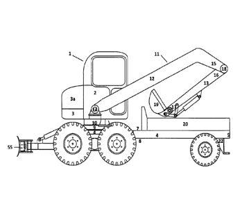
[0057] FIG.1 shows a side view of an illustrative embodiment of revolving
hydraulic
excavator 1. Excavator 1 includes an operator's cabin 2 mounted on top of the
mainframe 4 that
is capable of rotating 3600 in both directions about the excavator. Attached
to the operator's
17
CA 02980543 2017-09-21
WO 2015/143301 PCT/US2015/021718
cabin 2, is a counterweight 3 for balancing the cabin 2 and a motor
compartment 3a for housing
the motor of the excavator 1.
[0058] Still referring to FIG. 1, excavator 1 includes main frame 4. Main
frame 4 is an
elongated frame having a front end 5 and a rear end 6 and opposite facing top
7 and bottom 8
surfaces. A second frame 9 is fixedly connected to the top surface 7 of the
main frame 4. A
slidable plate (not shown in FIG. 1) is slidably engaged with second frame 9.
Rotatable base 10
is rotatably connected to the bottom wall of the operator's cabin 2 and the
slidable plate. Main
frame 4 is a mobile frame and includes a plurality of wheels that are engaged
with main frame 4
through axles.
[0059] Still referring to FIG. 1, excavator 1 includes an articulated arm 11
that is
connected to rotatable base 10. Articulated arm 11 includes a boom 12 and a
stick 13. The
boom 12 of the articulated arm 11 includes opposite first 14 and second 15
ends. The first end
14 of the boom 12 of the articulated arm 11 is pivotably connected to the
rotatable base 10 by a
suitable connection means. The stick 13 of the articulated arm 11 includes
opposite first 16 and
second 17 ends. The first end 16 of the stick 13 of articulated arm 11 is
pivotably attached to the
second end 15 of the boom 12 of the articulated arm 11 at pivot point 18.
Bucket 19 is pivotably
attached to the second end 17 of stick 13 of articulated arm 11.
[0060] Excavator 1 further includes dump bed 20. Dump bed 20 is removably
engaged
with the top surface 7 of the main frame 4 of the hydraulic excavator 1.
Excavator 1 also
includes blade assembly 55 and tow hitch 22.
18
CA 02980543 2017-09-21
WO 2015/143301 PCT/US2015/021718
[0061] FIG. 2 shows a side view of the excavator 1 with the operator's cabin 2
in a rear
facing position. The operator's cabin 2 and the articulated digging arm 11
have been rotated
180 from the forward facing front position. The boom 12 of the articulated
digging arm 11 has
been extended beyond the rear of the excavator 1. The stick 13 of the
articulated digging arm 11
has been pivoted to a position that is substantially perpendicular to the
ground surface. The
digging bucket 19 is shown resting on the ground.
[0062] FIG. 3 shows a front view of the excavator 1. Operator's cabin 2 is
mounted on
top of the rotatable base 10. The boom 12 and stick 13 of the articulate
digging arm 11 have
been retracted and second end of the stick 13 rests upon the top of the
rotating base 10. Dump
bed 20 is mounted on top of the main frame 4 of the excavator 1. A set of
wheels 64 are
positioned on opposite sides of the main frame 4 of the excavator 1 and are
attached to steering
axle 62.
[0063] FIG. 4 shows a front view of the excavator 1. Operator's cabin 2, motor
compartment 3 and counterweight 3a are mounted on top of rotatable base 10.
Rotatable base 10
is mounted on top of slidable plate 27. Wheels 88, 90 are mounted to drive
axle 85. Power
blade 55 is mounted to the main frame 4 of the excavator and extends beyond
the wheels 88, 90.
[0064] FIG. 5A shows a front view of the operator's cabin 2 mounted on top of
the
rotatable base 10 and second frame 9. FIG. 5B shows a side view of the
operator's cabin 2
mounted on top of the rotatable base 10 and second frame 9. As shown in FIGS.
5A and 5B,
second frame 9 includes spaced apart front 23 and rear 24 bars and spaced
apart side rails 25, 26.
19
CA 02980543 2017-09-21
WO 2015/143301 PCT/US2015/021718
Slidable plate 27 is slidably engaged with the side rails 25, 26 of the second
frame 9. Slidable
plate 27 includes opposite top 30 and bottom 31 surfaces and opposite front 32
and rear 33
edges. Hydraulic ram 34 is positioned below second frame 9 and slidable plate
27, and is
connected to rear bar 24 of second frame 9 and to the front edge 32 of
slidable plate 27 by a
suitable connection means such as hydraulic ram brackets 35. Slidable plate 27
is connected to
rotatable base 10, and slidable plate 27 and rotatable base move the
operator's cabin forward and
backward between the front 23 and rear 24 frame bars of the second frame 9.
The slidable plate
27 is able to slide forward and backwards along a portion of the main frame 4
within the
boundary established by the front bar 23 and rear bar 24 of the second frame
9. Thus, the
slidable plate, rotatable base 10, and the operator's cabin 2 can move
together forward and
backward in the direction of the longitudinal axis of the main frame 4 of the
excavator 1.
[0065] FIG. 6 shows a side view of excavator 1. The operator's cabin 2 of
excavator 1
has been rotated 90 to face the side of the excavator 1. Operator's cabin is
mounted on rotary
base 10. In turn, rotary base 10 is mounted on the weight slide frame 9. The
weight slide frame
9 is fixedly mounted to the underlying main frame 4 of the excavator I. Near
the front end 5 of
main frame 4 is mounted a dump bed 20. Tow hitch assembly 22 is extendably
mounted at the
front end 5 of the main frame 4. Mounted to the main frame 4 near the rear end
6 of frame 4 is
the power blade 55. Power blade 55 is mounted to the frame 4 by blade lift arm
56. Power blade
55 is shown in a downwardly position by power blade ram 51.
[0066] FIGS. 7A and 7B show an illustrative embodiment of the second frame 9
of the
excavator 1. Second frame 9 includes spaced apart front 23 and rear 24 bars
and spaced apart
CA 02980543 2017-09-21
WO 2015/143301 PCT/US2015/021718
side rails 25, 26. According to the illustrative embodiment shown in FIG. 7,
slidable plate 27 is
slidably engaged with the side rails 25, 26 of the second frame 9. Slidable
plate 27 may be
engaged with side rails 25, 26 through tubes 28, 29. Tube 28 is coaxially
positioned around side
rail 25 and tube 29 is coaxially positioned around side rail 26. Tubes 28, 29
are provided with a
suitable inner diameter that is larger than the outer dimensions of side rails
25, 26 to provide for
a clearance gap between the outer dimensions of side rails 25, 26 and the
inner diameter of tubes
28, 29. The clearance gap between the side rails 25, 26 and tubes 28, 29
permit the slidable plate
27 to slide or otherwise move back and forth between the spaced apart front 23
and rear 24 bars
of the second frame 9 along the side rails 25, 26. Slidable plate 27 includes
opposite top 30 and
bottom 31 surfaces and opposite front 32 and rear 33 edges. Hydraulic ram 34
is positioned
below second frame 9 and slidable plate 27, and is connected to rear bar 24 of
second frame 9
and to the front edge 32 of slidable plate 27 by a suitable connection means
such as hydraulic
ram brackets 35. Hydraulic ram 34 is capable of moving slide plate 27 forward
and backward
between the front bar 23 and rear bar 24 of second frame 9. Slidable plate 27
is connected to
rotatable base 10, which includes opening 36 for passing of hydraulic fluid
hosing and cabling
requirement to operate the excavator 1. The slidable plate 27 allows the
weight of the operator's
cabin 2 of the excavator 1 to shift forward and backward over the center of
the tandem axle
walking beam, which acts as a fulcrum point. The slidable plate 27 allows
weight to be
distributed where it needs to be in order to perform various digging
operations with the excavator
I. The ability to distribute the weight of the operator's cabin 2 of the
excavator also permits the
excavator 1 to be towed with the need for transporting the excavator with a
trailer.
21
CA 02980543 2017-09-21
WO 2015/143301 PCT/US2015/021718
[0067] FIG. 7C shows the operator's cabin 2 of the excavator 1 mounted on top
of
rotatable base 10 (also known as the slew ring or turret). The rotatable
turret 10 is mounted on
top of the slide plate 27 (not shown), which is reciprocally engaged with
second frame 9.
Second frame 9 is mounted on main frame 4. A hydraulic ram is engages with the
slidable plate
and the second frame 9 to move the slidable forward and backward in the
longitudinal direction
of the main frame 4 of the excavator 1.
[0068] FIG. 8 shows a top plan view of the illustrative embodiment of the
excavator
shown in FIG. 1 without showing the operator's cabin, slide plate assembly, or
optional dump
bed. The front end 5 of the main frame 4 includes wheels 64 that are engaged
with the
mainframe through front steering axle 62. Wheels 64 are mounted on each side
of the spaced
apart main frame 4 side rails 49, 50 of frame 4 and are attached to the
steering axle 62 by ball
joints 65. Dump bed hoist frame comprises a U-shaped dump bed hoist frame 67.
Dump bed
hoist frame 67 includes dump bed hoist legs 68, 69 which are connected by
connecting member
70. Dump bed hoist frame 67 is hingedly connected to the front end of main
frame 4 by dump
bed hoist frame hinges 71. Hydraulic rams 72, 73 are connected to the dump bed
hoist frame 67
with ram brackets 74, 75, and to main frame 4 with ram brackets 76, 77. Still
referring to FIG. 8,
a tandem axle walking beam assembly 80 is mounted near the rear end 6 of main
frame 4
through axle frame brackets 81, 82. Axle frame brackets 81, 82 are fixedly
connected to the
main frame 4. Drive axle 83 is connected to axle frame brackets 81, 82.
Walking beam axles
84, 85 are attached to the drive axle 83 through axle hubs 86, 87. Axle hubs
86, 87 house pivot
and braking means. Axle hubs 86, 87 permits walking beam axles 84, 85 to move
up and down
to follow the contour of the ground below being traversed by the excavator 1.
Wheels 88, 89 are
22
CA 02980543 2017-09-21
WO 2015/143301 PCT/US2015/021718
mounted on the outside of walking beam 84 by wheel axles. Wheels 90, 91 are
mounting on the
outside of walking beam axle 85 by wheel axles. Hydraulic motor 92 and
transmission power
and drive main drive axle 93. Power blade assembly 55 is mounted at the rear
end 6 of the
excavator 1.
[0069] FIG. 9 shows a fragmentary top view of the rear end of the excavator 1.
A tandem
axle walking beam assembly 80 is mounted near the rear end of main frame 4
through axle frame
brackets 81, 82. Axle frame brackets 81, 82 are fixedly connected to spaced
apart side rails 49,
50 of main frame 4. Drive axle 83 is connected to axle frame brackets 81, 82.
Walking beam
axles 84, 85 are attached to the drive axle 83 through axle hubs 86, 87. Axle
hubs 86, 87 house
pivot and braking means. Axle hubs 86, 87 permits walking beam axles 84, 85 to
move up and
down to follow the contour of the ground below being traversed by the
excavator 1. Wheels 88,
89 are mounted on the outside of walking beam axle 84. Wheels 90, 91 are
mounting on the
outside of walking beam axle 85. Hydraulic motor 92 and transmission power and
drive main
drive axle 93.
[0070] FIG. 10 is fragmentary top view of the front end of the excavator 1.
Front
steering axle 62 is mounted near the front end of main frame 4 through
steering axle frame 63.
Wheels 64 are mounted on each side of the spaced apart main frame side rails
49, 50 of frame 4
and are attached to the axle 62 by ball joints 65. Also mounted near the front
end of the main
frame 4 of the excavator 1 is the dump bed hoist frame for dump bed 20. Dump
bed hoist frame
67 comprises a U-shaped dump bed hoist frame 67. Dump bed hoist frame 67
includes dump
bed hoist legs 68, 69 which are connected by connecting member 70. Dump bed
hoist frame 67
23
CA 02980543 2017-09-21
WO 2015/143301 PCT/US2015/021718
is hingedly connected to the front end of main frame 4 by dump bed hoist frame
hinges 71.
Hydraulic rams 72, 73 are connected to the dump bed hoist frame 67 with ram
brackets 74, 75,
and to main frame 4 with ram brackets 76, 77.
[0071] FIG. 11A-11D show an illustrative embodiment of a power blade assembly
54 for
grading operations. Power blade assembly 54 is connected at the rear of the
main frame 4 of
excavator 1. Blade arms 56, 57 are attached to brackets 81, 82 at pivot points
56a, 57a. Power
blade assembly 54 includes blade 55 attached to blade lift arms 56, 57.
Hydraulic rams 58, 59
are connected to blade lift arms 56, 57. Hydraulic rams 58, 59 move blade 55
up and down
during an excavating operation or during transport of the excavator 1. Power
blade assembly 54
also includes blade tilt control means 60. Blade tilt control means 60 include
hydraulic rams
60a, 60b and is capable of tilting the blade 55 at various angles from the
neutral position (the
neutral position is a position that is substantially horizontal to the ground)
in the same vertical
plane. Blade assembly 54 further includes blade angle control means 61. Blade
angle control
means 61 includes hydraulic rams 61a, 61b and controls the angling of the
blade 55 to the left
side and right side of the neutral position (the neutral position is the
position where the blade 56
faces substantially rearwardly of the mainframe 4). The power blade 55 can be
referred to as a
six-way motion blade as it is able to move up and down, tilt at different
angles in the same
vertical plane, and angle to the left and right of the neutral position.
Hydraulic ram bracket 35 is
used to connect a hydraulic ram between the blade assembly 55 and the
excavator 1.
[0072] FIGS. 12A and 12B are top view of the extendable tow hitch 22.
Extendable tow
hitch 22 comprises a frame having elongated and spaced apart legs 37, 38. Each
of legs 37, 38 of
24
CA 02980543 2017-09-21
WO 2015/143301 PCT/US2015/021718
tow hitch 22 have opposite ends 39-42. Ends 39, 41 of legs 37, 38 of tow hitch
22 are connected
near one end by cross-member 43. Extending outwardly from cross-member 43 in
the same
plane are arms 44, 45 that are joined at junction point 46. The opposite ends
40, 42 of tow hitch
legs 37, 38 are free. Now referring to FIG. 12C, the tow hitch 22 is
extendably engaged with the
main frame 4 of the excavator 1. Main frame 4 includes spaced apart and
elongated side rails 49,
50. The free ends 40, 42 of tow hitch legs 37, 38 are inserted into, and are
housed within, the
elongated spaced apart side rails 49, 50 of the main frame 4. The hydraulic
rams 51, 52 are used
to extend and retract the tow hitch 22 from the main frame 4. Hydraulic rams
51, 51 are attached
to cross-member 43 at attachment points 53a. The other ends of the hydraulic
rams 51, 52 are
attached to main frame 4. Referring to FIG. 12E, depending substantially
downwardly from
junction point 46 is flange member 47. Flange member 47 has opposite upper and
lower ends.
Tow eye hook 48 is attached to the lower end of the flange member 47.
[0073] FIGS. 13A-13C show partial side views of the excavator 1. Excavator
includes
operator's cabin 2, motor compartment 3, and counterweight 3a. The operator's
cabin 2 of the
excavator 1 mounted on top of rotatable base 10 (also known as the slew ring
or turret). The
rotatable turret 10 is mounted on top of the slide plate 27 (not shown), which
is reciprocally
engaged with second frame 9. Second frame 9, which includes front bar member
23, rear bar
member 24 and side rail 26, is mounted on main frame 4. Axle bracket 82 is
connected to the
side of main frame 4 and drive axle 83 is mounted to the main frame 4 through
the axle bracket
82. FIG. 13B shows the operator's cabin 2 in the neutral position with the
weight of the cabin 2
positioned over the center of the drive axle 83. FIG. 13A shows the operator's
cabin 2 with the
weight of the cabin 2 shifted rearwardly of the center of the drive axle 83
toward the rear end 6
CA 02980543 2017-09-21
WO 2015/143301 PCT/US2015/021718
of the excavator 1. FIG. 13C shows the operator's cabin 2 with the weight of
the cabin 2 shifted
forwardly of the center of the drive axle 83 toward the front end 5 of the
excavator 1.
[0074] FIG. 14 shows a side view of the illustrative embodiment of the
excavator 1
shown in FIG. 1 with the optional dump bed 20 shown in the dumping position.
Dump bed 20
has been raised into dumping position by hydraulic ram 20a that is connected
to dump bed hoist
frame 67. To hitch 22 is shown in the fully retracted position within its legs
positioned within
the main frame 4. Operator's cabin 2 and articulated digging arm 11 have been
rotated 90 to
face the side of the excavator 1. Power blade assembly 55 is shown in the
neutral position.
[0075] FIG. 15 is a side view of the illustrative embodiment of the excavator
shown in
FIG. 1 with weight of the operator's cabin distributed for transporting the
excavator. Using the
slidable plate 27, the weight of the operator's cabin 2 has been shifted
backward toward the rear
end 6 of the excavator 1 such that the weight of the cabin 2 is shifted
rearward of the drive axle
83. This shifting of the weight raises the front end 5 and wheels 64 of the
excavator 1 off of the
ground for transport. The power blade assembly 55 with blade 56 is shown
raised off of the
ground and in the neutral position for transport. The articulated digging arm
11 resting in the
dump bed 20, and tow hitch 22 attached to a vehicle for transporting the
excavator 1 to or from a
construction jobsite.
[0076] FIGS. 16A and 16B show cross sectional views of the slip ring assembly
100.
Slip ring 100 is connected to and is positioned within a generally circular
opening passing
through the thickness of the rotatable base 10 of the excavator 1. Slip ring
assembly 100
26
CA 02980543 2017-09-21
WO 2015/143301 PCT/US2015/021718
includes a top stationary portion 101 and a bottom rotatable portion 102 that
is in fluid
communication with top stationary portion 101. Top stationary portion 101 is
fixedly connected
to the rotatable base 10 with connectors 111, 112 and rotates with base 10.
Bottom portion 102
of the slip ring assembly 100 is connected to the slide plate 27 through
connectors 113, 114.
According to the embodiment shown in FIGS. 16A and 16B, bottom portion 102 is
rotatable
independently of top portion 101 and rotatable base 10. The top surface 104 of
top portion 101
includes an inlet 105 for receiving hydraulic fluid from a source of hydraulic
fluid for operating
the various functionality of the excavator 1. Inlet 105 includes suitable
coupling or connection
means for connecting the top portion 101 of the slip assembly 100 to conduit
delivering
hydraulic fluid from a hydraulic fluid source to the assembly 100. The top
surface 104 of top
portion 101 includes an outlet 108 for receiving used hydraulic fluid and
removing it from the
slip ring assembly 100. Outlet 108 includes suitable coupling or connection
means for
connecting the top portion 101 of the slip assembly 100 to conduit 110
returning used hydraulic
fluid. An elongated passageway 103 acting as a cable and hosing run is
centrally disposed and
passes through top 101 and bottom 102 portions of the slip ring assembly 100.
Hydraulic hosing
115 delivers hydraulic fluid from above the rotatable base 10, via a plurality
of hydraulic fluid
hosing branches 115a, to a valve bank 116 positioned below the slip ring
assembly 100. The
illustrative embodiment shown in the FIG. 16B shows a bank of 10 valves.
However, this is
merely an illustrative embodiments and the valve bank may include any number
of valves
depending on the number of implements on the excavator that need to be
operated.
[0077] FIG. 17A is a top view of an illustrative embodiment of the tandem axle-
walking
beam assembly movably engaged with the main frame. FIG. 18A shows a
fragmentary top view
27
CA 02980543 2017-09-21
WO 2015/143301 PCT/US2015/021718
of the rear end of the excavator 1. A tandem axle walking beam assembly is
movably mounted
on main frame 4 through axle frame slide channels 81a, 82a. Axle frame slide
channels 81a, 82a
are fixedly connected to spaced apart side rails of main frame 4. Drive axle
83 is connected to
axle frame slide channels 81a, 82a. Walking beam axles 84, 85 are attached to
the drive axle 83
through axle hubs 86, 87. Axle hubs 86, 87 house pivot and braking means. Axle
hubs 86, 87
permits walking beam axles 84, 85 to move up and down to follow the contour of
the ground
below being traversed by the excavator I. Wheels 88, 89 are mounted on the
outside of walking
beam axle 84. Wheels 90, 91 are mounting on the outside of walking beam axle
85. Hydraulic
motor 92 and transmission 93 power and drive main drive axle 83. Linear
actuator screw blocks
121, 122 are engaged with axle slide channels 81a, 82a. Linear actuator screws
127, 128 are
engaged with screw blocks 121, 122, screw bearings 123, 124, and gear motor
125, 126. FIG.
17B is a side with of the operator's cabin mounted on the movable tandem axle-
walking beam
assembly of FIG. 17A. FIG. 17B shows the operator's cabin 2 in the neutral
position with drive
axle 83 located below the center of the cabin 2. In this position, the weight
of the cabin 2 is
positioned over the center of the drive axle 83. Operator's cabin 2 is mounted
on rotatable base
10. Rotatable base 10 is mounted on plate 129. Plate 129 is mounted to main
frame 4 in a
stationary position. The tandem axle walking beam assembly is driven by the
linear actuator and
can move in the direction of the longitudinal axis of the main frame. The
plate 129 is mounted in
a fixed position on the main frame and operator's cabin 2, while being able to
rotate 360 , cannot
translate forward and backward in the direction of the longitudinal axis of
the excavator.
[0078] FIG. 18A-18C are partial side views of an illustrative embodiment of
the
excavator with the operator's cabin mounted on the main frame of the excavator
with the
28
CA 02980543 2017-09-21
WO 2015/143301 PCT/US2015/021718
movable tandem axle-walking beam assembly positioned in different positions
along the
longitudinal axis of the main frame. Excavator includes operator's cabin 2,
motor compartment
3, and counterweight 3a. The operator's cabin 2 of the excavator 1 is mounted
on top of
rotatable base 10 (also known as the slew ring or turret). The rotatable
turret 10 is mounted on
top of the main frame 4. Axle bracket 82 is connected to the side of main
frame 4 and drive axle
83 is mounted to the main frame 4 through the axle bracket 82. According to
the embodiment of
the excavator 1 shown in FIGS. 18A-18C, an actuator is used to move the tandem
axle-walking
beam assembly forward and backward along the longitudinal axis of the
excavator 1. FIG. 188
shows the operator's cabin 2 in the neutral position with drive axle 83
located below the center
of the cabin 2. In this position, the weight of the cabin 2 is positioned over
the center of the
drive axle 83. The actuator includes linear actuator screw block 121, actuator
screw bearing 124,
actuator gar motor 126 and linear actuator screw 128. FIGS. 18A and 18C show
the tandem axle
walking beam assembly moved to a position by the linear actuator to a position
both forwardly
and rearwardly of the operator's cabin 2 of the excavator 1.
[0079] While the excavator has been described in connection with various
illustrative
embodiments, it is to be understood that other similar embodiments may be used
or
modifications and additions may be made to the described embodiments for
performing the same
function disclosed herein without deviating therefrom. The embodiments
described above are
not necessarily in the alternative, as various embodiments may be combined to
provide the
desired characteristics. Therefore, the excavator should not be limited to any
single embodiment,
but rather construed in breadth and scope in accordance with the recitation of
the appended
claims.
29