Note: Descriptions are shown in the official language in which they were submitted.
CA 02980550 2017-09-21
WO 2016/153799 PCT/US2016/021712
1
SHAVING RAZOR CARTRIDGE
FIELD OF THE INVENTION
The present invention relates to wet shaving safety razors and more
particularly to
shaving cartridges that have a housing for retaining and/or rigidly fixing one
or more blades.
BACKGROUND OF THE INVENTION
In general, a cartridge or blade unit of a safety razor has at least one blade
with a cutting
edge which is moved across the surface of the skin being shaved by means of a
handle to which
the cartridge is attached. Some shaving razors are provided with a spring
biased cartridge that
pivots relative to the handle to follow the contours of the skin during
shaving. The cartridge may
be mounted detachably on the handle to enable the cartridge to be replaced by
a fresh cartridge
when the blade sharpness has diminished to an unsatisfactory level, or it may
be attached
permanently to the handle with the intention that the entire razor be
discarded when the blade or
blades have become dulled. Razor cartridges usually include a guard which
contacts the skin in
front of the blade(s) and a cap for contacting the skin behind the blade(s)
during shaving. The cap
and guard may aid in establishing the so-called "shaving geometry", i.e., the
parameters which
determine the blade orientation and position relative to the skin during
shaving, which in turn
have a strong influence on the shaving performance and efficacy of the razor.
The cap may
comprise a water leachable shaving aid to reduce drag and improve comfort. The
guard may be
generally rigid, for example formed integrally with a frame or platform
structure which provides
a support for the blades. Guards may also comprise softer elastomeric
materials to improve skin
stretching.
Wet shaving razors have evolved over the years to include multiple blades that
are spaced
closer together. The increased number of blades and decreased spacing often
creates clogging
issues. For example, shaving debris becomes difficult to rinse from the
shaving razor cartridge
housing. Excessive shaving debris can negatively impact shaving performance,
such as shaving
efficiency (i.e., missed hairs) and closeness. Thus, there is a need for a
safety shaving razor
cartridge having a housing to retain the blades in place during a shaving
stroke, while also
improving the removal of shaving debris (i.e., rinsibility).
SUMMARY OF THE INVENTION
CA 02980550 2017-09-21
WO 2016/153799 PCT/US2016/021712
2
In one aspect, the invention features, in general a shaving razor cartridge
with a housing
having a guard at a front portion of the housing, a cap at a rear portion of
the housing and a first
blade support member positioned between the guard and the cap. The first blade
support member
has a first blade retention member spaced apart from a second blade retention
member to define a
first blade slot. The first blade support defines at least one rinse opening
in communication with
the first blade slot and extending completely through the housing.
BRIEF DESCRIPTION OF THE DRAWINGS
Other features and advantages of the present invention, as well as the
invention itself, can
be more fully understood from the following description of the various
embodiments, when read
together with the accompanying drawings, in which:
FIG. 1 is a perspective view of a shaving razor cartridge according to one
possible
embodiment of the present invention.
FIG. 2 is a cross section view of the shaving razor cartridge, taken generally
along the
line 2-2 of FIG. 1
FIG. 3 is an assembly view of the shaving razor cartridge of FIG. 1
FIG. 3A is a perspective view of the housing of FIG. 3.
FIG. 4 is a top view of a housing, which may be incorporated into the shaving
razor
cartridge of FIG. 1.
FIG. 4A is an enlarged top view of a left hand side of the housing of FIG. 4.
FIG. 4B is an enlarged top view of a right hand side of the housing of FIG. 4.
FIG. 5 is a cross section view of the shaving razor cartridge, taken generally
along the
line 5-5 of FIG. 1
FIG. 5A is an enlarged view of the left hand side of the shaving razor
cartridge of FIG. 5.
FIG. 5B is an enlarged view of the right hand side of the shaving razor
cartridge of FIG.
5.
FIG. 6 is an enlarged view of the left hand side of the shaving razor
cartridge of FIG. 5
with four blades removed.
DETAILED DESCRIPTION OF THE INVENTION
CA 02980550 2017-09-21
WO 2016/153799 PCT/US2016/021712
3
Referring to FIG. 1, a perspective view of a shaving razor cartridge 10 is
shown. The
shaving razor cartridge 10 may be mounted to handle (not shown). The shaving
razor cartridge
may be removable or permanently mounted to the handle. For example, the
shaving razor
cartridge 10 may be mounted detachably on a handle to enable the shaving razor
cartridge 10 to
5 be replaced by a fresh shaving razor cartridge 10 when the blade
sharpness has diminished to an
unsatisfactory level, or it may be attached permanently to the handle with the
intention that the
entire razor be discarded when the blade or blades have become dulled. The
shaving razor
cartridge may include a housing 12. The housing 12 may be molded out of a
rigid plastic or
manufactured from other materials, such as metal. A guard 14 may be positioned
at a front
10 portion 16 of the housing and a cap 18 may be positioned at a rear
portion 20 of the housing 12.
The guard 14 is typically a unitary molded member that can be formed of a
rigid plastic (e.g., the
same material as the housing 10). In certain embodiments, the cap 18 may
comprise one or more
lubricants that are released during a shaving stroke.
One or more blades 22, 24, 26, 28 and 30 may be mounted to the housing 12
between the
cap 18 and the guard 14 (i.e., in front of the cap 18 and behind the guard
14). The blades 22, 24,
26, 28, and 30 may each have a respective cutting edge 32, 34, 36, 38, and 40
generally directed
towards the guard 14. A primary blade 22 may be nearest the guard 14,
secondary blade 24 is
next nearest the guard 14, and so on until the fifth blade 30 is furthest from
the guard 14.
Although five blades 22, 24, 26, 28 and 30 are shown, the housing 12 may have
more or fewer
blades depending on the desired performance and cost of the shaving razor
cartridge 10. The
guard 14 and the cap 18 may define a shaving plane that is tangent to the
guard 14 and the cap
18. The guard 14 may be a solid or segmented bar that extends generally
parallel to the blades
22, 24, 26, 28 and 30 and supports the skin during a shaving stroke. In
certain embodiments, the
housing 12 may comprise a skin-engaging member 15 (e.g., a plurality of fins
or other
protrusions) in front of the guard 14 for stretching the skin during a shaving
stroke. In certain
embodiments, the skin-engaging member 15 may be insert injection molded or co-
injection
molded to the housing 12. However, other known assembly methods may also be
used such as
adhesives, ultrasonic welding, or mechanical fasteners. The skin engaging
member 15 may be
molded from a softer material (i.e., lower durometer hardness) than the
housing 12, such as an
elastomer.
Referring to FIG. 2, a cross section of the shaving cartridge 10 is shown,
taken generally
along the line 2-2 of FIG. 1. One or more of the blades 22, 24, 26, 28 and 30
may be a bent blade
unit. For example, each blade 22, 24, 26, 28 and 30 may comprise a unitary
member having a
base portion 42, 44, 46, 48 and 50 and respective bent portion 52, 54, 56, 58
and 60 located
CA 02980550 2017-09-21
WO 2016/153799 PCT/US2016/021712
4
between the respective cutting edge 32, 34, 36, 38, 40 and the base portion
42, 44, 46, 48 and 50.
The base portions 42, 44, 46, 48 and 50 may be generally parallel to each
other and transverse to
a shaving plane P1 that is tangent to the guard 14 and the cap 18. In other
embodiments, the one
or more of the blades may be welded blade assemblies (e.g., a blade welded
having a cutting
edge connected to a blade support having a base portion and a bent portion).
FIG. 2 illustrates
shaving forces Fl may exert a force on the blades 22, 24, 26, 28 and 30 in a
direction from the
guard 14 toward the cap 18. Accordingly, the blades 22, 24, 26, 28 and 30 may
rock backwards
toward the cap 18 during a shaving stroke. The movement of the blades 22, 24,
26, 28 and 30
may increase as the thickness and rigidity of the blades 22, 24, 26, 28 and 30
decreases. The
blades 22, 24, 26, 28 and 30 may have a support height "SH1" of about 1.5mm to
about 2.5mm.
For example, the height of the portion of the blade, such as the base 42, that
is supported and or
contacted by the housing 12.
Referring to FIG. 3, an assembly view of the shaving razor cartridge 10 is
shown. In
certain embodiments, the blades 22, 24, 26, 28 and 30 may be mounted to the
housing 12 and
secured by one or more clips 62 and 64 located at opposite lateral sides of
the housing 12. The
blades 22, 24, 26, 28 and 30 may be fixed in the housing 12 or may be
resiliently mounted such
that the blades 22, 24, 26, 28 and 30 are biased against the clips 62 and 64.
The clips 62 and 64
may aid in retaining the blades 22, 24, 26, 28 and 30 in an up and down
direction (i.e., toward
and away from a top surface 55 of the housing 12). Each of the clips 62 and 64
may extend
completely thru the housing 12. The clips 62 and 64 may comprise a metal, such
as aluminum or
plastic. The clips 62 and 64 may also be interconnected to form a one piece
assembly. Other
assembly methods known to those skilled in the art may also be used to secure
and/or mount the
blades 22, 24, 26, 28 and 30 to the housing 12 including, but not limited to,
wire wrapping, cold
forming, hot staking, insert molding, ultrasonic welding, and adhesives.
In certain embodiments, it may be important to retain the blades 22, 24, 26,
28 and 30 in a
shaving direction for improved efficiency and comfort. As shown in FIG. 2,
shaving forces Fl
may exert a force on the blades 22, 24, 26, 28 and 30 in a direction from the
guard 14 toward the
cap 18. Accordingly, one or more blade support members 66, 68, 70 and 72 (as
shown in FIG. 3)
may be provided to resist rearward movement of the blades 22, 24, 26, 28 and
30. The blade
support members 66, 68, 70 and 72 may be spaced apart for improved rinsing of
the shaving
razor cartridge 10. In certain embodiments, the blade support members 66, 68,
70 and 72 may be
positioned between the clips 62 and 64 (e.g., laterally inboard) and between
the guard 14 and the
cap 18. Although four blade support members 66, 68, 70 and 72 are shown, more
or less blade
support members may be used depending on the desired level of blade rigidity
and rinsing
CA 02980550 2017-09-21
WO 2016/153799 PCT/US2016/021712
desired. For example, more blade support members 66, 68, 70 and 72 may improve
blade
rigidity, but additional blade support members tend to decrease rinsibility.
Referring to Fig. 3A, a perspective view of the housing 12 of the shaving
razor cartridge
in FIG. 3 is illustrated. Each of the blade support members 66, 68, 70 and 72
of the housing
5 12 may define at least one slot dimensioned to receive one of the
respective blades. For example,
the blade support members 66, 68, 70 and 72 may each define a first blade slot
74, 76, 78 and 80
to receive the primary blade 22. The first slots 74, 76, 78, and 80 may be
generally aligned with
each other and parallel to a longitudinal axis Al of the housing 12 to allow
for assembly of the
primary blade 22 (as shown in FIG. 3) to the housing 12. Similarly, the blade
support members
10 66, 68, 70 and 72 may each define a second slot 82, 84, 86 and 88. The
second slots 82, 84, 86
and 88 may also be generally aligned with each other and parallel to the
longitudinal axis Al of
the housing 12 to receive the secondary blade 24 (e.g., a base portion 44 of
the secondary blade
24, as shown in FIG. 3). Accordingly, the blade support members 66, 68, 70 and
72 may have
additional slots to receive the other blades 26, 28 and 30 (as shown in FIG.
3) in a similar
fashion. For example, the blade support members 66, 68, 70 and 72 may each
define a third
blade slot 90, 92, 94 and 96 to receive the third blade 26 (e.g., a base
portion 46 of the third blade
26, as shown in FIG. 3). The blade support members 66, 68, 70 and 72 may each
define a fourth
blade slot 98, 100, 102 and 104 to receive the fourth blade 28 (e.g., a base
portion 48 of the
fourth blade 28õ as shown in FIG. 3). Lastly, the blade support members 66,
68, 70 and 72 may
each define a fifth blade slot 106, 108, 110 and 112 to receive the fifth
blade 30 (e.g., the base
portion 50 of the fifth blade 30, as shown in FIG. 3).
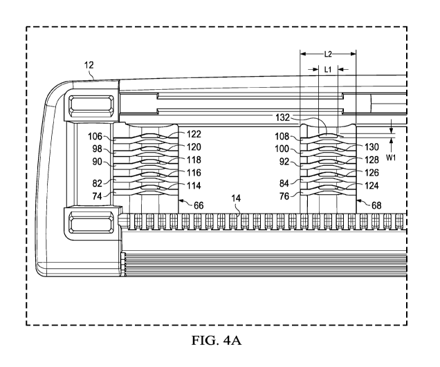
Referring to FIGS. 4, 4A and 4B several top views of the housing 12 are shown.
FIG. 4
is a top view of the entire housing 12. FIG. 4A is an enlarged view of the
left hand side of the
housing 12 and FIG. 4B is a right hand view of the housing 12. The blade
support members 66,
68, 70 and 72 may be spaced apart and parallel to each other (e.g., transverse
to the guard 14) to
define open spaces there between. The spacing of the blade support members 66,
68, 70 and 72
may allow for water to rinse the blades (not shown) and help prevent clogging.
In certain
embodiments, the blade support members 66, 68, 70 and 72 may define one or
more rinse
openings 114, 116, 118, 120, 122, 124, 126, 128, 130 and 132 (as shown in FIG.
4A) and 134,
136, 138, 140, 142, 144, 146, 148, 150 and 152 (as shown in FIG. 4 extending
completely thru
the housing 12. The rinse openings 114, 116, 118, 120, 122, 124, 126, 128,
130, 132, 134, 136,
138, 140, 142, 144, 146, 148, 150 and 152 may extend thru a bottom surface of
the housing 12
such that they are not obstructed by the housing 12 or other features, such as
the clips 62 and 64
(not shown). For example, the clips 62 and 64 (as shown in FIG. 3) may be
outboard (e.g.,
CA 02980550 2017-09-21
WO 2016/153799 PCT/US2016/021712
6
laterally) of the blade support members 66, 68, 70 and 72 and thus the rinse
openings 114, 116,
118, 120, 122, 124, 126, 128, 130, 132, 134, 136, 138, 140, 142, 144, 146,
148, 150 and 152 as
well. As shown in FIG. 4A, first blade support member 66 may define the
plurality of rinse
openings 114, 116, 118, 120 and 122 that are in communication with
corresponding blade slots
74, 82, 90, 98, 106. For example, rinse opening 114 may be in communication
with the first
blade slot 74. The blade slots 74, 82, 90, 98, 106 may extend generally
parallel to the guard 14 to
receive the respective blades 22, 24, 26, 28 and 30 (not shown). It is
understood that the other
blade support members 68, 70 and 72 may have similar rinse openings in
communication with
respective blade slots. As shown in FIG. 4A, the second blade support member
68 may have
rinse openings 124, 126, 128, 130 and 132 that are in communication with
respective blade slots
76, 84, 92, 100 and 108. As shown in FIG. 4B, the third blade support member
70 may have
rinse openings 134, 136, 138, 140 and 142 that are in communication with
respective blade slots
78, 86, 94, 102 and 110. The fourth blade support member 72 may have rinse
openings 144, 146,
148, 150 and 152 that are in communication with respective blade slots 80, 88,
96, 104 and 112.
The rinse openings may be dimensioned to provide maximum rinsing while still
providing sufficient rigidity to support the blades. For example, the rinse
opening 132 may have
a length Li (i.e., in a direction parallel to the guard 14 and or blade 22) of
about 0.5mm to about
2mm. The blade support member 68 may have a length L2 (parallel to the guard
and or blade 22)
of about 2.0mm to about 5.0mm. The rinse openings may be elongated (e.g., also
have a
minimum width w 1 that is less than the length L1). In certain embodiments,
the minimum width
w 1 may be about 0.1mm to about 0.325mm. The other rinse openings may be
similarly
dimensioned.
Referring to FIGS. 5, 5A and 5B section views of the shaving razor cartridge
10 are
illustrated, taken generally along the line 5-5 of FIG. 1. FIG 5A is an
enlarged left hand side
view of FIG. 5 and FIG. 5B is an enlarged right hand side view of FIG. S. In
certain
embodiments, each of the blade support members 66, 68, 70 and 72 may have a
plurality of blade
retention members that extend upwardly in a transverse direction from the
corresponding blade
support member 66, 68, 70 and 72. As shown in FIG. 5A, the first blade support
66 member may
have a first blade retention member 154 nearest the guard 14 (not shown), a
second blade
retention member 156 behind the first blade retention member 154, a third
blade retention
member 158 behind the second blade retention member, a fourth blade retention
member 160
behind the third blade retention member 158, a fifth blade retention member
162 behind the
fourth blade retention member 160, and a sixth blade retention member 164
behind the fifth blade
retention member 162 and closest to the cap 18. The blade retention members
154, 156, 158,
CA 02980550 2017-09-21
WO 2016/153799 PCT/US2016/021712
7
160, 162 and 164 may be generally aligned with each other along the blade
support member 66.
In certain embodiments, the sixth blade retention member 164 may project from
an inner wall
166 (e.g., toward the guard 12) of the housing 12 and the first blade
retention member 154 may
project from an opposing inner wall 168 of the housing 12 (e.g., toward the
cap 18) for increased
rigidity.
The second blade support member 68 may have a first blade retention member 170
nearest the guard 14, a second blade retention member 172 behind the first
blade retention
member 170, a third blade retention member 174 behind the second blade
retention member 172,
a fourth blade retention member 176 behind the third blade retention member
174, a fifth blade
retention member 178 behind the fourth blade retention member 176 and a sixth
blade retention
member 180 nearest the cap 18 and behind the fifth blade retention member 178.
In certain
embodiments, the sixth blade retention member 180 may project from the inner
wall 166 of the
housing 12 and the first blade retention member 164 may project from the
opposing inner wall
168 of the housing 12 for increased rigidity.
As shown in FIG. 5B, the third blade support member 70 may have a first blade
retention
member 182 nearest the guard 14, a second blade retention member 184 behind
the first blade
retention member 182, a third blade retention member 186 behind the second
blade retention
member 184, a fourth blade retention member 188 behind the third blade
retention member 186,
a fifth blade retention member 190 behind the fourth blade retention member
188, a sixth blade
retention member 192 behind the fifth blade retention member 190 and nearest
the cap 18. In
certain embodiments, the sixth blade retention member 192 may project from the
inner wall 166
of the housing 12 and the first blade retention member 182 may project from
the opposing inner
wall 168 of the housing 12 for increased rigidity.
The fourth blade support member 72 may have a first blade retention member 194
nearest
the guard 14, a second blade retention member 196 behind the first blade
retention member 194,
a third blade retention member 198 behind the second blade retention member
196, a fourth blade
retention member 200 behind the third blade retention member 198, a fifth
blade retention
member 202 behind the fourth blade retention member 200 and a sixth blade
retention member
204 behind the fifth blade retention member 202 and nearest the cap 18.
Referring to FIGS. 5A
and 5B, the primary blade 22 may be retained between the first blade retention
members 154,
170, 182 and 194 and the second blade retention members 156, 172, 184 and 196.
The first blade
retention members 154, 170, 182 and 194 and the second blade retention members
156, 172, 184
and 196 may define the respective blade slots 74, 76, 78 and 80 previously
described and
illustrated in FIGS. 4A and 4B. The secondary blade 24 may be retained between
the second
CA 02980550 2017-09-21
WO 2016/153799 PCT/US2016/021712
8
blade retention members 156, 172, 184 and 196 and the third blade retention
members 158, 174,
186 and 198. The third blade 26 may be retained between the third blade
retention members 158,
174, 186 and 198 and the fourth blade retention members 160, 176, 188 and 200.
The fourth
blade 28 may be retained between the fourth blade retention members 160, 176,
188 and 200 and
the fifth blade retention members 162, 178, 190 and 202. The fifth blade 30
blade may be
retained between the fifth blade retention members 162, 178, 190 and 202 and
the sixth blade
retention members 164, 180, 192, and 204.
The blade retention members may have a wave shape structure to facilitate
rinsing and
retaining the blades 22, 24, 26, 28 and 30 (e.g., to prevent rearward rocking
of the blades 22, 24,
26, 28 and 30 during a shaving stroke). It is understood that all of the blade
retention members
may have a similar structure and function. Accordingly, only a limited number
of the blade
retention members will be described in detail. Referring to FIG. 6, the
housing 12 may provide
a first pair of spaced apart blade contact surfaces 206 and 208 on a common
wall 210 (i.e., a front
wall of the blade retention member 156) that are spaced apart from a second
pair of spaced apart
blade contact surfaces 212 and 214 on another common wall 216 (i.e., a front
wall of the blade
retention member 166). The first pair of spaced apart blade contact surfaces
206 and 208 may
extend in an upward direction from the first blade support member 66 and the
second pair of
spaced apart blade contact surfaces 212 and 214 may extend from the second
blade support
member 68. The base portion 42 of the primary blade 22 may have a rear wall
218. The rear
wall 218 of the primary blade 22 may contact both pairs of spaced apart blade
contact surfaces
206, 208, 212 and 214 during a shaving stroke. The common walls 210 and 216
may comprise
plastic or metal, depending on the desired stiffness to support the blades 22
(blades 24, 26, 28
and 30 not shown).
The first pair of spaced apart blade contact surfaces 206 and 208 may be
spaced apart by
a first distance "Dl" that is less than a distance "Al" between the pair of
common walls 210 and
216. Similarly, the second pair of spaced apart blade contact surfaces 212 and
214 may be
spaced apart by a second distance "D2" that is less than the distance Al
between the pair of
common walls 210 and 216. In certain embodiments, the first distance D1 and
the second
distance D2 may be about 1.0mm to about 3.5mm and the distance Al between the
common
walls 210 and 216 may be about 4.0mm to about 10.0mm. The first distance D1
and the second
distance D2 may be equal (e.g., within typical manufacturing tolerances) or
similar (e.g., within
10% of each other). The first distance D1 (and/or second distance D2) may be
about 20% to
about 40% of the distance Al between the pair of common walls 210 and 216 to
provide
sufficient blade retention and minimize rocking of the primary blade 22, while
still allowing for
CA 02980550 2017-09-21
WO 2016/153799 PCT/US2016/021712
9
sufficient open space for rinsing the blades. The first distance and the
distance between the pair
of common walls 210 and 216 may vary depending on a thickness of the base of
the primary
blade 22. For example, a thinner blade may require more support than a thicker
blade. In certain
embodiments, the thickness of the base of the blades (e.g., primary blade 22)
may be about
0.07mm to 0.160mm. The other blades may have a similar thickness for the base.
In certain embodiments, the housing 12 may have a support ratio less than 4.0
(e.g., about
2.5 to about 3.0). The support ratio may be equal to the distance Al between
the pair of common
walls 210 and 216 divided by the support height "SH1" (as shown in FIG. 2). If
the distance Al
is too large, deflection of the blade increases as forces are applied to the
blades during a shaving
stroke. If the support height "SH1" is too small, the blades and or the
cutting edges of the blades
may rock or bend in a rearward direction.
The common walls 210 and 216 may be a variety of different shapes and sizes in
order to
provide spaced apart blade contact surfaces having the proper spacing. For
example, as shown in
FIG. 6, the common walls 210 and 216 may have a wave-like shape. The common
walls 210 and
216 may each have a respective 220 and 222 trough (e.g., a concave surface
facing toward the
guard) in-between the pair of spaced apart blade contact surfaces.
Accordingly, the primary blade
may not contact the troughs 220 and 222, but only the pair of spaced apart
blade contact surfaces
206, 208, 212 and 214. The troughs 220 and 222 may allow for sufficient
spacing for the rinse
thru openings 114, 116, 118, 120, 122, 124, 126, 128, 130, 132 (as shown in
FIG. 4A).
The housing 12 may also have a wall 224 spaced apart from and in front of the
common
wall 210 of the first pair of spaced apart blade contact surfaces 206 and 208
(e.g., the wall 224 is
positioned toward the guard 14). For example, the wall 224 may be a rear wall
of the first blade
retention member 154. The wall 224 in front of the common wall 210 may have a
single blade
contact surface 226 positioned between the first pair of spaced apart blade
contact surfaces 212
and 214 and faces a front wall 228 of the base 42 of the primary blade 22. The
blade contact
surface 226 may be generally aligned with the trough 220 (i.e., the area of
the common wall 216
that does not contact the primary blade). Similarly, the housing 12 may also
have a wall 230
spaced apart from and in front of the common wall 216 of the second pair of
spaced apart blade
contact surfaces 212 and 214 (e.g., toward the guard 14). For example, the
wall 230 may be a
rear wall of the first blade retention member 164. The wall 230 in front of
the common wall 216
may have a single blade contact surface 232 positioned between the second pair
of spaced apart
blade contact surfaces 212 and 214 and faces the front wall 228 of the base 42
of the primary
blade 22. The blade contact surface 232 may be generally aligned with the
trough 222 (i.e., the
area of the common wall 216 that does not contact the primary blade 22).
CA 02980550 2017-09-21
WO 2016/153799 PCT/US2016/021712
The primary blade 22 may be assembled between the first pair of spaced apart
blade
contact surfaces 206 and 208 and the blade contact surface 226 to create three
closely spaced
areas of contact with the primary blade 22 (two at the rear face 218 of the
primary blade 22 and
one at the front face 228 of the primary blade). Similarly, primary blade 22
may also be
5 assembled between the second pair of spaced apart blade contact surfaces
212 and 214 and the
blade contact surface 232 to create three closely spaced areas of contact with
the primary blade
22 (two at the rear face 218 of the primary blade 22 and one at the front face
228 of the primary
blade). It is understood that additional blade contact surfaces may be
provided as those described
above for the first and second blade retention members 154, 156, 164 and 166.
In certain
10 embodiments, these three contact areas may be within a contact length
"CL" of about 2.0mm to
about 5.0mm. The contact length "CL" may be the length of the respective
common wall 210
and/or the wall 224. Accordingly, a length of the common wall 210 that
contacts the base of the
blade may be the difference between CL and Dl. A length of the common wall 216
that contact
the base of the blade may be the difference between CL and D2. During shaving,
the primary
blade 22 may contact the first pair of spaced apart blade contact surfaces 206
and 208 and the
second pair of spaced apart blade contact surfaces 212 and 214 to minimize
blade movement,
which may lead to discomfort and an inefficient shave. In addition, the blade
contact surfaces
226 and 232 may be spaced apart from the primary blade during a shaving stroke
because the
shaving forces move the blades in a rearward direction toward the cap 18.
It is understood the blade retention members 158, 160, 162 and 164 of the
first blade
retention member 66 may be similarly shaped to hold the other blades 24, 26,
28 and 30. It is
also understood that the other blade support members 68, 70 and 72 also have
similarly shaped
blade retention members to provide sufficient support to retain the other
blades 24, 26, 28 and 30
during a shaving stroke. The rigidity of the blade retention members may be
increased by having
pairs of spaced apart blade contact surfaces that are interconnected (i.e., on
the common wall)
instead of being spaced apart from each other. The increased rigidity of the
blade retention
members may allow for easier molding of the housing, easier assembly of the
blades and
decreased movement of blades during a shaving stroke.
The dimensions and values disclosed herein are not to be understood as being
strictly
limited to the exact numerical values recited. Instead, unless otherwise
specified, each such
dimension is intended to mean both the recited value and a functionally
equivalent range
surrounding that value. For example, a dimension disclosed as "40 mm" is
intended to mean
"about 40 mm."