Note: Descriptions are shown in the official language in which they were submitted.
CA 02980566 2017-09-21
WO 2016/154242 PCT/US2016/023667
INTEGRATED PROCESS CONTROLLER WITH LOOP AND
VALVE CONTROL CAPABILITY
FIELD OF THE DISCLOSURE
[0001] The present invention relates generally to process plant systems and,
more
particularly, to controllers capable of driving control loops in a field.
DESCRIPTION OF THE RELATED ART
[00021 The background description provided herein is for the purpose of
generally
presenting the context of the disclosure. Work of the presently named
inventors, to the extent
it is described in this background section, as well as aspects of the
description that may not
otherwise qualify as prior art at the time of filing, are neither expressly
nor impliedly
admitted as prior art against the present disclosure.
[0003] Process control systems, such as those used in chemical, petroleum or
other process
plants, typically include one or more process controllers communicatively
coupled to one or
more field devices via analog, digital or combined analog/digital buses, or
via a wireless
communication link or network. The field devices, which may be, for example,
valves, valve
positioners, switches, and transmitters (e.g., temperature, pressure, level
and flow rate
sensors), are located within the process environment and generally perform
physical or
process control functions such as opening or closing valves, measuring process
parameters,
etc. to control one or more process executing within the process plant or
system. Smart field
devices, such as field devices conforming to the well-known Fieldbus protocol
may also
perform control calculations, alarming functions, and other control functions
commonly
implemented within the controller. The process controllers, which are also
typically located
within the plant environment, receive signals indicative of process
measurements made by
sensors and/or field devices and/or other information pertaining to the field
devices and
execute a controller application that runs, for example, different control
modules that make
process control decisions, generate control signals based on the received
information and
coordinate with the control modules or blocks being performed in the field
devices, such as
HART . Wireless HART , and FOUNDATION Fieldbus field devices. The control
modules in the controller send the control signals over the communication
lines or links to the
- 1 -
CA 02980566 2017-09-21
WO 2016/154242 PCT/US2016/023667
field devices to thereby control the operation of at least a portion of the
process plant or
system.
[0004] Information from the field devices and the controller is usually made
available over
a data highway to one or more other hardware devices, such as operator
workstations,
personal computers or computing devices, data historians, report generators,
centralized
databases, or other centralized administrative computing devices that are
typically placed in
control rooms or other locations away from the harsher plant environment. Each
of these
hardware devices typically is centralized across the process plant or across a
portion of the
process plant. These hardware devices run applications that may, for example,
enable an
operator to perform functions with respect to controlling a process and/or
operating the
process plant, such as changing settings of the process control routine,
modifying the
operation of the control modules within the controllers or the field devices,
viewing the
current state of the process, viewing alarms generated by field devices and
controllers,
simulating the operation of the process for the purpose of training personnel
or testing the
process control software, keeping and updating a configuration database, etc.
The data
highway utilized by the hardware devices, controllers and field devices may
include a wired
communication path, a wireless communication path, or a combination of wired
and wireless
communication paths.
[0005] Fig. 1 illustrates an example known system 10, in which a valve 10
operates in a
pipeline 12 to maintain a certain flow rate, pressure, or another variable. A
PID controller 14
implements the proportional-integral-derivative (PID) logic for a control loop
that includes
the valve 10. To this end, the PID controller 14 receives sensor measurements
from a sensor
20 (in this example, a pressure sensor), which a transmitter 22 communicates
to the PID
controller 14 via a set of communication links 40. The PID controller 14 also
provides
commands for controlling the valve 10 to an VP positioner 30 via the
communication links
40, and the I/P positioner 30 can operate upon an actuator 42 to actuate
(e.g., open and close)
the valve 10. The PID controller 14 can receive commands from, and provide
reports to, an
operator workstation 50. The PID controller 14 also can be communicatively
coupled to a
database that stores diagnostics data, historical data, etc.
[0006] In some implementations, the communication links 40 can include wired
links
interconnected via hubs, switches, etc., and/or wireless links forming a mesh
network. In any
case, the PID controller 14 exchanges information with the devices 30, 22,
etc. via a
- 2 -
CA 02980566 2017-09-21
WO 2016/154242 PCT/US2016/023667
relatively complex communication path, and may control the loop with a
significant delay.
For example, the PID controller 14 can receive, from the operator workstation
50, a new
setpoint for the flow rate in the pipeline 12 and begin executing PID control
by transmitting
specific valve positioning commands to the I/P positioner 30. In response to
pressure
measurements from the pressure sensor 20 or, more generally, sensor
measurements reported
by sensor operating in the field, the PID controller 14 may provide new
positioning
commands. Thus, to drive the valve 10 to the new setpoint within a certain
period of time,
the controller 14 and the devices 30, 22 may exchange numerous messages, each
having a
potentially significant propagation delay.
[0007] For similar reasons, the PID controller 14 cannot carry out diagnostic,
prognostic,
maintenance functions, and other functions related to the valve 10 (or the
control loop
including the valve 10) without a delay. For example, to collect diagnostics
data for storage
in the database 52, the PID controller 14 may need to transmit multiple
requests for data and
collect multiple responses via the communication links 40.
[0008] In addition to propagation delays, the system 10 has several other
limitations. For
example, the components 20, 22, and 30 must be procured, installed, wired, and
maintained
separately, thereby increasing complexity, cost, demands on personnel, etc.
Moreover, the
relatively large number of separate devices operating in control loops makes
diagnostics more
difficult.
SUMMARY
[0009] An integrated digital process controller of this disclosure is
configured to operate in
a field to locally perform process value measurements and implement PID
control. The
controller can receive a setpoint from a remote host for a process variable,
such as pressure or
flow rate in a pipeline, and locally, independently of the remote host, carry
out control of a
loop that includes a field device such as a valve. In particular, the
controller can implement
control without communicating measurements or receiving adjusted control
parameters from
the remote host. Components operating within the controller can exchange data
at wire speed
over small distances, in some cases even at on-chip speed, thereby making
control quick and
efficient. The controller can operate in a local loop, a distributed control
system, or a
SCADA system.
- 3 -
CA 02980566 2017-09-21
WO 2016/154242 PCT/US2016/023667
[00101 In addition to the implementing PID control, the controller can perform
real-time
learning and diagnostics using data stored locally, e.g., in a non-volatile
memory module of
the integrated module. The controller can generate alerts and alarms based on
the locally
performed measurements and diagnostics. The controller can store this as well
as signature
data for efficient comparison in local memory, thereby eliminating the need to
report
measurements to a remote host and rely on the remote host for calculation. The
controller
can perform diagnostics not only on the field device but on the entire control
loop, and
similarly can adjust parameters related to both the field device and the
control loop.
Moreover, the controller can optimize control loop performance for all process
variable types,
such as flow, pressure, level, density, pH, temperature, composition, etc.
[00111 According to some implementations, the controller is assembled in a
modular
manner to enable quick and cost-efficient of components such as sensors, UP
converters, etc.
Thus, a component can be easily replaced in the event of failure or when an
upgrade is
available. Further, the controller can be equipped with redundant components
to ensure
immediate service restoration (e.g., hot swap) in the event of failure and
supports voting logic
in discrete applications.
[0012] In some embodiments, the controller further can include one or more of
the
following features: (i) the housing of the controller can be explosion-proof
and compliant
with intrinsic safety (IS) standards; (ii) the controller can include no-bleed
pneumatics, to be
used in natural gas applications, for example; (iii) the controller can
include a power source
that can provide sufficient power to the CPU and/or other processing units to
carry PID
calculations, support transmissions, and otherwise support largely autonomous
operation of
the controller in the field; (iv) the controller can receive setpoint data
from, as well as provide
alerts, alarms, and reports to, a remote host via a wireless link; (v) the
controller can support
Ethernet connectivity, (vi) in addition to wired or wireless interface for
communicating with a
remote host, the controller can include a local user interface for receiving
configuration data
and displaying alerts or alarms, for example; (vii) the controller also can
support remote use
interface (RUT) for a standard operating platform used by a remote host, such
as Windows ,
for example; and (viii) the controller can include analog output (AO) and
analog input (Al) 4
¨ 20 mA modules to operate with legacy field devices.
- 4 -
CA 02980566 2017-09-21
WO 2016/154242 PCT/US2016/023667
DETAILED DESCRIPTION OF THE DRAWINGS
[0013] Fig. 1 is a block diagram of a known remote terminal unit coupled to a
field device;
[0014] Fig. 2 is a block diagram of an example integrated controller of this
disclosure;
[0015] Fig. 3 is a flow diagram of an example method for executing PID control
of a loop
in accordance with the techniques of this disclosure;
[00161 Fig. 4 is a flow diagram of an example method for conducting
diagnostics in situ at
an integrated controller of this disclosure; and
[0017] Fig. 5 is a flow diagram of an example method for conducting real-time
diagnostics
during operation of a field device or a control loop, which can be implemented
in the
integrated controller of this disclosure.
DETAILED DESCRIPTION
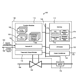
[00181 Fig. 2 illustrates an example integrated digital process controller
(for simplicity,
"controller") 100 capable of carrying out control in a field using local
measurements and
local control functions. As discussed below, the controller 100 is capable of
fast, dynamic in
situ process control for various types of process variables, performance
optimization, real-
time diagnostics, etc. By implementing PID control directly at a valve or
another field
device, the controller 100 can deliver improved loop performance. Moreover,
the controller
100 effectively replaces several devices, thereby simplifying installation and
maintenance. A
single supplier can provide the controller 100 for total loop control.
[0019] In the example configuration of Fig. 2, the controller 100 operates on
a valve 102
installed in a pipeline 104. The valve 102 and the pipeline 104 can be similar
to the valve 10
and the pipeline 12 discussed above with reference to Fig. 1. The controller
100 includes
function modules 110, a memory 112 and a pneumatic output module 114. In some
implementations, the controller 100 also can include a sensor, such as a
pressure sensor 116.
Further, the integrated controller 100 can include a network interface module
118 and a
power conditioner 120. Still further, the integrated controller 100 can be
equipped with a
local user interface module 122. Depending on the implementation, the
components 100 ¨
120 can reside in a same housing 130, or some of the components (e.g., the
pressure sensor
116) can be provided in a separate housing, but in any case the components 100
¨ 122 can be
interconnected using direct local wired links, or other suitable types of
short-range, high-
- 5 -
CA 02980566 2017-09-21
WO 2016/154242
PCT/US2016/023667
speed communication links. In an example implementation, the components 100 ¨
122 are
coupled to a backplane 124. The controller 100 can receive a setpoint for a
process variable
and configuration data via a communication line 150, and provide process
information and
reports to a remote host via a communication line 152. The lines 150 and 152
are not
necessarily physically separate channels, and in general can be communication
channels on a
same wire or a set of wires, different radio channels or different timeslots
of a same channel,
or any other suitable types of physical or logic channels.
[0020] Next, the components 110 ¨ 124 are briefly considered individually,
followed by a
discussion of operation of the controller 100.
[0021] Depending on the implementation, the function modules 110 can include a
general-
purpose central processing unit (CPU) configured to execute instructions
stored in the
memory 112 and/or one or several special-purpose modules, such as application-
specific
integrated circuits (ASICs) configured to execute YID functions. The CPU can
include a
real-time clock accurate to within a certain number of minutes (e.g., 10) per
year over the
entire range of temperatures at which the controller 100 can operate. More
generally, the
function modules 110 can include one or more processors of any suitable type.
As
schematically illustrated in Fig. 2, the function modules 110 can implement
one or several
PID functions 160, one or several tuning functions 162, one or several real-
time positioning
and/or diagnostics functions 164, and, if desired, additional functions
related to monitoring,
troubleshooting, process variability optimization, etc. The function modules
110 can
implement these functions in hardware, firmware, software instructions
executable by one or
more processors, or any suitable combination of hardware, firmware, and
software.
[0022] In an example scenario, the function modules 110 receives a pressure
setpoint via a
communication line 150 for the pipeline 104 from a remote host via the network
interface
118, receives sensor data from the pressure sensor 116, executes a Pm
algorithm to generate
a positioning command (or, more generally, an output signal), and applies the
positioning
command to the valve 102 via the pneumatic output module 114. It is noted that
the function
modules 110 can receive a setpoint for a process variable rather than for a
field device. The
function modules 110 can retrieve the tuning parameters for the PID loop from
the memory
112. These parameters can be pre-configured, received from a remote host,
determined
and/or adjusted used auto-tuning, etc., as discussed in more detail below.
Thus, the function
module 110 can use locally collected sensor data to locally, without relying
on a remote host,
- 6 -
CA 02980566 2017-09-21
WO 2016/154242 PCT/US2016/023667
execute control functions. Depending on the implementations, the function
modules 110 can
implement functions to control many different process variables, such as
pressure, position,
temperature, flow rate, or pH.
[00231 More generally, the function modules 110 allow the integrated
controller 100 to
quickly and efficiently react to device issues (e.g., detect a problem with
the valve 102, detect
failure of the sensor 116), control loop issues (e.g., determine that PID
parameters should be
adjusted), carry out emergency procedures (e.g., shut down flow through the
pipeline 104),
generate alerts for output via the local UI module 122 and/or for reporting to
a remote host.
[0024] The memory 112 can be any suitable non-transitory computer-readable
medium and
can include volatile and/or non-volatile components. Thus, the memory 112 can
include
random-access memory (RAM), a hard disk, a flash drive, or any other suitable
memory
components. The memory 112 can store PID parameters 170, diagnostics data 172,
valve
signature data 174, and process signature data 176. In particular, the PID
parameters 170 can
specify proportional, derivate, and integral gain values for a loop
controlling the valve 102 or
another field device. The PID parameters 170 can be provided configured by a
remote
operator via a remote host and provided via the network interface 118, a local
operator via the
UI module 122, pre-stored in the memory 112 by the manufacturer of the
integrated
controller 100, etc. In some scenarios, the integrated controller 100 can
adjust PID
parameters 170 in response to receiving a new setpoint 150 or upon conducting
diagnostics,
for example.
[0025] The valve signature data 174 and the process signature data 176 can
describe
expected behavior of the valve 102 and the loop for controlling the valve 102,
respectively.
For example, a valve signature can include a set of expected sensor
measurements
corresponding to a set of respective positions of the valve 102. In the
example
implementation of Fig. 2, the valve signature can specify how the pressure
sensor 116,
disposed downstream of the pressure sensor 116 and thus corresponding to the
output
pressure of the valve 102, relates to the travel positions of the valve 102
(which can be
measured as the position of the travel actuator or the percentage of the open
position, for
example). Similarly, a process signature data can describe expected process
output values,
such as pressure measurements from the pressure sensor 116, in response to the
changes in
the setpoint value or an input value. More generally, signatures stored in the
memory 112
- 7 -
CA 02980566 2017-09-21
WO 2016/154242 PCT/US2016/023667
can describe the expected response of a sub-system to input signals, for
comparing to the
actual response of the sub-system and determining whether the sub-system
operates properly.
[0026] Unlike the systems known today, the integrated controller 100 can
locally collect
data for determining the actual response to a sub-system such as the valve 102
and again
locally compare the collected data to the signature 174, the signature 176, or
another
signature. In this manner, the integrated controller can quickly and
efficiently detect valve
problems (e.g., actuator being stuck, pressure loss, leakage of fluid),
process upsets, control
loop degradation, etc. Further, if desired, the integrated controller 100 can
execute the
appropriate tuning function 162 to create a process signature. Using the
process signature,
the controller can detect a suitable set of tuning parameters for the desired
control loop
response.
[0027] Further, the memory 112 can retain configuration information, logs,
history data,
status of input and output ports, etc. The integrated process controller 100
can be configured
to retain in the memory 112 an event log, an alert log, real-time clock data,
a loop log,
historical data, database data, status of input/output channels, function
module attributes, user
lists, etc., in the event of a power failure.
[0028] With continued reference to Fig. 2, the pneumatic output module 114 can
actuate
the valve 102 during operation. The pneumatic output module 114 can include an
UP
transducer and one or more relay components. In an example implementation, the
pneumatic
output module 114 includes an UP module and a double-acting relay. Further, in
one
implementation, the pneumatic output module 114 includes a relay that bleeds
and one that
locks in the last value in the event of a power failure. The controller 100
can provide
indications of output pressure of the pneumatic output module 114 via the
local UI 122 or the
RUI of a remote host. It is noted that the controller 100 can monitor
operation of the
pneumatic output module 114 by sensing output pressure, for example, and
perform real-time
diagnostics to detect complete or partial failure early.
[0029] When used in applications in which natural gas is the medium, the
controller 100
can include one or several no-bleed pneumatic components to comply with
emission
regulations.
The controller 100 in these implementations allows continued use of the medium
while
reducing the emissions compared to traditional pneumatic devices.
- 8 -
CA 02980566 2017-09-21
WO 2016/154242 PCT/US2016/023667
[00301 In an example implementation, the pressure sensor 116 is an integral
pressure
sensor module configured to measure pressure as the process variable (PV). The
pressure
sensor 116 may bolt directly to the housing 130. In alternative
implementations, however,
the pressure sensor 116 can be provided as a separate device coupled to the
controller 100 by
a wired link or a short-range wireless link. Similar to the pneumatic output
module 114
discussed above, the controller 100 can display live data for the pressure
sensor 116 via the
(local) UI module 122 or the RUI at the remote host. Further, the controller
100 can support
commands using which an operator can request, or pull, live data via the local
or remote
interface.
[0031] Although the example implementation depicted in Fig. 2 includes a
pressure sensor
116 integral with the remaining assembly of the controller 100, in other
implementations the
controller 100 can include additional I/0 modules such as a valve position
sensor or a
temperature sensor. These and other modules can be inserted into the backplane
124, or the
controller 100 can communicate with the additional modules via short-range
communication
links.
[0032] The network interface module 118 can support general-purpose protocols
such as
the Internet Protocol (IP) as well as special-purpose process control and
industrial automation
protocols designed to convey commands and parameters for controlling a process
plant, such
as Modbus, HART, Profibus, etc. The network interface module 118 can support
wired
and/or wireless communications. As discussed above, the controller 100 can
receive a
setpoint value from a remote host via a long-range communication link to which
the network
interface module 188 is coupled. The network interface module 118 can support
Ethernet
ports and, in some implementations, implement protection against unauthorized
access.
[00331 Still referring to Fig. 2, the power conditioner 120 can receive power
from a power
supply via line(s) 123 to provide sufficient power for the function modules
110 to carry out
PID control and communicate with local as well as remote devices. The power
conditioner
120 can include a DC-to-DC converter, for example, to convert 8 ¨ 30V of DC
power to the
level necessary to power the components coupled to the backplane 124.
Generally speaking,
the power conditioner 120 can ensure a substantially autonomous operation of
the controller
100 to control the valve 102 and the corresponding control loop.
- 9 -
CA 02980566 2017-09-21
WO 2016/154242 PCT/US2016/023667
[0034] The local user interface module 122 can include any suitable display,
such as a
liquid crystal display (LCD), a keyboard and/or a touchscreen, etc. In some
implementations, the user interface module 122 also can include an audio
output device such
as speaker and/or an audio input device such a microphone. In other
implementations, the
components of the user interface module 122 are selected in view of intrinsic
safety
considerations to minimize the risk of explosion. Further, the controller 100
can support
remote user interface for accessing certain features and/or data stored in the
controller 100
from a remote host, such as the host 50discussed above with reference to Fig.
1.
[00351 The backplane 124 can be a component with no active circuitry, residing
in the
housing 130 and having connections for mounting various modules. As
illustrated in Fig. 2,
the backplane 124 can interconnect the function modules 110, the memory 112,
the network
interface 118, the power conditioner 120, the UI module 122, the pneumatic
output module
114, etc. The backplane 124 in general can include connections to receive
power, select lines,
communication ports, etc. In some implementations, the CPU module is selected
or designed
so as to prevent mis-insertion into the backplane 124.
[00361 The housing 130 can be explosion-proof, compliant with intrinsically
safety (IS)
standards. In some implementations, the integrated controller 100 includes
barriers to
interface to the pressure sensors/IF, and the display to keep the integrity of
the disclosure as
Class 1 Division 1 (C1D1) explosion-proof.
[00371 As indicated above, the controller 100 can have modular design to allow
removal/swap of disabled or obsolete components. In some implementations, the
controller
100 can support hot swap, or replacement of components without taking the
system offline.
Modular and flexible design can allow certain operators to customize the
system by
equipping the controller 100 with only some of the modules and/or easily
replace
components. For example, the controller 100 can be provided without a pressure
sensor or
without a pneumatic output module. Further, the control strategy can be
customized by
selecting desired electronic I/0 or function modules for connection to the
backplane 124.
[00381 In operation, the controller 100 can perform real-time prognostics to
allow
operators to quickly gain accurate insight into process changes, issues
related to the valve
102, transmissions and communications, control maintenance, etc. Thus, the
controller 100
can carry out control functions in the field. In other words, rather than
operating based on
- 10 -
CA 02980566 2017-09-21
WO 2016/154242 PCT/US2016/023667
commands generated by a remote host that implements a PID loop, the controller
100 can
control the valve 102 and/or loop parameters locally and, if desired, report
information to a
host via a communication network via the communication line 152.
[0039] Further, although the controller 100 can receive the setpoint value 150
via a
wireless communication link, which may introduce a communication delay, the
controller
100 then can drive the process variable to the setpoint using wired signaling
between
components within the same devices, or even on-chip signaling. More
specifically, the
controller 100 need not report pressure, position, temperature, level, flow
rate, or other
measurements to another device capable of calculating new control signals.
Updates to the
setpoint therefore may be limited by the speed of wireless communications, but
communications between sensors, modules calculating proportional, derivate,
and integral
values, etc. occur at higher speeds.
[0040] In general, the techniques discussed below can be used in a variety of
applications,
such as upstream oil and gas, midstream oil and gas, liquid pipelines, gas
transmission, gas
distribution, electric power, chemical, petrochemical, refining, pulp and
paper, food and
beverage, pharmaceutical, water and wastewater, mining and metal, liquid
distribution,
liquefied natural gas (LNG) liquefaction and gasification. Further, these
techniques can be
used with both continuous and discrete control schemes to ensure accurate
process control at
a valve, enable real-diagnostic capabilities, and provide one or more of the
other advantages
discussed in this disclosure. In short, the controller 100 can increase
efficiency, reduce
downtime, provide a cost-effective option, etc.
[0041] For further clarity, example operation of the controller 100 to control
a process loop
is briefly discussed with reference to Fig. 3. A method 200 of Fig. 3 can be
implemented in
the function modules 110 and the memory 112 as a set of software or firmware
instructions,
for example. The method 200 begins at block 202, where a setpoint is received
from a remote
host via a communication link. The setpoint can be pressure or flow rate in a
pipeline, for
example.
[0042] At block 204, a controller begins to generate output to drive the loop
to the received
setpoint, using locally stored PID parameters. These parameters, which can
include gains for
the proportional, derivative, and integral blocks, can be stored in the memory
112, for
example. Depending on the implementation and/or scenario, the controller is
pre-configured
-11-
CA 02980566 2017-09-21
WO 2016/154242 PCT/US2016/023667
with these parameters, or the controller receives these parameters during a
separate
configuration procedure. As indicated above, the controller in some cases may
dynamically
adjust these parameters.
[00431 At block 206, the process variable is measured locally using a sensor
integral with
the controller or coupled to the controller via a short-range communication
link. The control
loop then is executed locally at block 208. For example, the controller 100
can execute PID
logic without relying on a remote host and without reporting inteimediate
measurements
(e.g., the measurements collected at block 206) to the remote host. When
executing the PID
logic, logical or physical blocks within the controller can exchange data at
wire speed or at
on-chip speed, depending on the implementation. hi any case, the speed at
which
components of the controller exchange data is substantially higher than the
speed at which the
controller can communicate with a remote host. The method 100 can include
multiple
calculations and measurements at block 206 and 208, until the set point is
reached.
[00441 A report optionally can be provided to the remote host at block 210.
The report can
include non-time-critical data, and can be delivered via the relatively slow
wired or wireless
links to the remote host. If desired, output also can be provided via a local
user interface.
[0045] Now referring to Fig. 4, a method 300 also can be implemented in the
function
module 110 and the memory 112 as a set of software or firmware instructions.
According to
the method 300, a controller executes in situ diagnostics, again without
relying on external or
remotely disposed controllers, hosts, or databases. The controller can execute
the method
300 when the field device is not operational, for example, or shortly after
installation and
prior to going online.
[0046] At block 302, diagnostics data is retrieved from a local memory, such
as the
memory 112 discussed above. The diagnostics data can include a valve
signature, a process
signature, or other data for comparing to the current output of the field
device. A controller
then can drive the corresponding field device (e.g., the valve 102) through
multiple positions
to generate output values (block 304). At block 306, feedback or another
output value is
collected from the field device using local sensors and local P/I transducers.
Next, at block
308, local processing can be carried out to compare the stored diagnostics
data to the actual
output of the field device to determine whether the output matches the
diagnostics data and,
in the event of deviation, whether an alert or an alarm should be generated.
- 12 -
CA 02980566 2017-09-21
WO 2016/154242 PCT/US2016/023667
[0047] Blocks 304 - 308 can be executed in real time and using local
processing
capabilities rather than a remote host. Blocks 304 ¨ 208 can be executed
repeatedly,
periodically, or according to any suitable schedule.
[0048] Fig. 5 illustrates another method for conducting diagnostics, which can
be
implemented in the controller 100 or another controller consistent with this
disclosure.
Unlike the method 300 discussed above, the method 400 does not require that
the field device
be driven through a set of values during a test session or a dedicated
diagnostics session.
Rather, according to the method 400, a controller monitors operation of a
field device during
operation. In other words, as the field device (e.g., a valve) operates in
response to receiving
a device setpoint, and/or as a control loop including the field device
operates in response to
receiving a process variable setpoint, the controller collects sensor data to
perform non-
intrusive, real-time diagnostics. Accordingly, the method 400 include blocks
402 ¨ 410 that
are generally similar to blocks 302¨ 310 discussed with reference to Fig. 3,
except that
various positions and/or output values during normal operation of the field
device are
monitored at block 404.
[0049] In some cases, the results of executing blocks 304 ¨ 308 are reported
to an operator
and/or a remote host. For example, an alarm can be generated and displayed via
the local
user interface (e.g., the UI module 122) , a report can be sent to a remote
host via a long-
range communication link, etc. The controller in some scenarios may adjust PID
tuning
parameters in response to the results of comparing the diagnostics data to the
output. In any
case, a controller can execute the method 300 to quickly and efficiently
perform in situ
diagnostics, adjustments, optimization, etc.
General considerations
[0050] Unless specifically stated otherwise, discussions herein using words
such as
"processing," "computing," "calculating," "determining," "identifying,"
"presenting,"
"displaying," or the like may refer to actions or processes of a machine
(e.g., a computer) that
manipulates or transforms data represented as physical (e.g., electronic,
magnetic, or optical)
quantities within one or more memories (e.g., volatile memory, non-volatile
memory, or a
combination thereof), registers, or other machine components that receive,
store, transmit, or
display information.
- 13 -
[0051] When implemented in software, any of the applications, services,
engines, routines,
and modules described herein may be stored in any tangible, non-transitory
computer
readable memory such as on a magnetic disk, a laser disk, solid state memory
device,
molecular memory storage device, an optical disk, or other storage medium, in
a RAM or
ROM of a computer or processor, etc. Although the example systems disclosed
herein are
disclosed as including, among other components, software and/or firmware
executed on
hardware, it should be noted that such systems are merely illustrative and
should not be
considered as limiting. For example, it is contemplated that any or all of
these hardware,
software, and firmware components could be embodied exclusively in hardware,
exclusively
in software, or in any combination of hardware and software. Accordingly,
persons of
ordinary skill in the art will readily appreciate that the examples provided
are not the only
way to implement such systems.
[0052] Thus, while the present invention has been described with reference to
specific
examples, which are intended to be illustrative only and not to be limiting of
the invention, it
will be apparent to those of ordinary skill in the art that changes, additions
or deletions may
be made to the disclosed embodiments without departing from the spirit and
scope of the
invention.
[0053] The following aspects represent examples of embodiments of the
presently
described systems and methods. This list of aspects is intended to be non-
limiting, as other
embodiments are contemplated in view of the present description.
1. An integrated controller configured to operate in a field, the
integrated
controller comprising:
a network interface module configured to receive, from a remote host via a
communication link, a setpoint for a process variable;
a sensor configured to generate a measurement of the process variable;
one or more function modules communicatively coupled to the sensor, the one or
more function modules being configured to i) receive the measurement of a
process variable
and ii) execute logic for a control loop including a field device based at
least in part on the
measurement of the process variable and the setpoint for the process variable,
to generate an
Output signal independently of the remote host, wherein the output signal is
for controlling
the field device;
an output module to directly apply the generated output signal to the field
device; and
- 14 -
Date Recue/Date Received 2023-06-08
a memory readable by the one or more function modules;
wherein the field device is a valve;
wherein the memory further stores a valve signature specifying a set of
pressure
values and a set of corresponding travel positions for the valve; and
wherein the one or more function modules are further configured to:
receive, during operation of the control loop in real time, pressure values
and
indications of travel positions for the valve, and
compare the received pressure values and indications of the travel positions
to
the valve signature to determine a set of tuning parameters for the control
loop.
2. The integrated controller of aspect 1, wherein the sensor is configured
to
provide the measurement to the one or more function modules via a short-range
communication link.
3. The integrated controller of aspect 1 or 2, wherein the sensor is
configured to
provide the measurement to the one or more function modules without reporting
the
measurement to the remote host.
4. The integrated controller of any one of aspects 1 to 3, wherein:
the network interface module, the one or more function modules, and the output
module are configured to exchange data at a first speed,
the integrated controller is configured to exchange data with the remote host
at a
second speed, and
the first speed is higher than the second speed.
5. The integrated controller of any one of aspects 1 to 4, wherein the
memory
further stores parameters for the control loop, the parameters including
proportional,
derivative, and integral proportional-integral-derivative (PID) values for
executing PID
control.
- 15 -
Date Recue/Date Received 2023-06-08
6. The integrated controller of aspect 5, wherein the one or more function
modules are configured to adjust one or more PID values during operation of
the control
loop.
7. The integrated controller of any one of aspects 1 to 6, wherein the one
or more
function modules are further configured, in response to detecting that the
valve does not
operate properly, transmit an alarm message to the remote host.
8. The integrated controller of any one of aspects 1 to 7, wherein the
memory
further stores:
a process signature specifying a set of process variable values and a set of
corresponding input values, and
wherein the one or more function modules are further configured to i) receive,
during
operation of the control loop in real-tine, process variable values and
indications and
corresponding input value, and ii) compare the received process variable
values and the
corresponding received input values to the process signature to determine
whether the control
loop operates properly.
9. The integrated controller of any one of aspects 1 to 8, wherein the one
or more
function modules are further configured, in response to detecting that the
control loop does
not operate properly, transmit an alarm message to the remote host.
10. The integrated controller of any one of aspects 1 to 9, further
comprising:
a power conditioner to provide power to the one or more function modules, the
network interface, and the output module for autonomous operation.
11. The integrated controller of any one of aspects 1 to 10, wherein to
execute the
logic for the control loop, the one or more function modules is configured to
calculate
proportional, derivative, and integral PID values for the control loop.
12. The integrated controller of any one of aspects 1 to 11, further
comprising
explosion-proof assembly.
- 16 -
Date Recue/Date Received 2023-06-08
13. The integrated controller of any one of aspects 1 to 12, wherein the
one or
more function modules include a tuning function to automatically adjust PID
parameters of
the control loop at run time.
14. The integrated controller of any one of aspects 1 to 13, wherein the
output
module is a no-bleed pneumatic module.
15. The integrated controller of any one of aspects 1 to 14, further
comprising:
a backplane to removeably receive components, wherein the components include
the
network interface module, the one or more function modules, and the output
module, to
support selective replacement of one or more of the components.
16. A method for operating a control loop in a field, the method
comprising:
receiving, at an integrated controller directly coupled to a field device, a
setpoint for a
control loop including the field device, from a remote host, the field device
being a valve;
monitoring, locally at the integrated controller using a sensor housed as a
component
of the integrated controller, a process variable generated by the control
loop;
generating, locally at the integrated controller, an output value for driving
the control
loop to the setpoint based at least in part on the setpoint and the monitored
process variable;
executing, locally at the integrated controller, logic for the control loop to
drive the
control loop to the setpoint, including applying the generated output value to
the field device
via an output module;
wherein receiving, during operation of the control loop in real time, pressure
values
and indications of travel positions for the valve; and
comparing the received pressure values and indications of the travel positions
to a
valve signature specifying a set of pressure values and a set of corresponding
travel positions
for the valve to determine a set of tuning parameters for the control loop.
General considerations
[0054] Unless specifically stated otherwise, discussions herein using words
such as
"processing,"" computing," "calculating," "determining," "identifying,"
"presenting,"
"displaying," or the like may refer to actions or processes of a machine
(e.g., a computer) that
manipulates or transforms data represented as physical (e.g., electronic,
magnetic, or optical)
- 17 -
Date Recue/Date Received 2023-06-08
quantities within one or more memories (e.g., volatile memory, non-volatile
memory, or a
combination thereof), registers, or other machine components that receive,
store, transmit, or
display information.
- 18 -
Date Recue/Date Received 2023-06-08