Note: Descriptions are shown in the official language in which they were submitted.
PROCESSES AND SYSTEMS FOR CONTROLLING COOLING FLUID
[0001]
FIELD OF THE INVENTION
[0002] This invention relates generally to an ionic liquid reactor and
more particularly
to an ionic liquid reactor with a heat exchange zone, and even more
particularly to a process
and system for providing the cooling fluid for the heat exchange zone.
BACKGROUND OF THE INVENTION
[0003] Ionic liquids are essentially salts in a liquid state, and are
described in U.S. Pat.
No. 4,764,440, U.S. Pat. No. 5,104,840, and U.S. Pat. No. 5,824,832. The
properties vary
extensively for different ionic liquids, and the use of ionic liquids depends
on the properties of
a given ionic liquid. Depending on the organic cation of the ionic liquid and
the anion, the ionic
liquid can have very different properties. The behavior of the ionic liquid
varies considerably
with temperatures, and it is preferred to find ionic liquids that do not
require operation under
more extreme conditions such as refrigeration.
[0004] Acidic ionic liquid may be used as a catalyst in various chemical
reactions, such
as for the alkylation of iso-paraffins with olefins. The alkylation reaction
is highly exothermic.
To control the temperature, it is common for part of the unreacted light
hydrocarbons to be
vaporized. However, controlling the temperature by vaporization is undesirable
because it
makes the reactor operation, the ionic liquid dispersion, and the acid
concentration more
difficult to control. Therefore, it is believed to be more desirable to
control the temperature
while the reactants and products are maintained in liquid form.
- 1 -
CA 2981120 2019-03-27
CA 02981120 2017-09-26
WO 2016/205036 PCMJS2016/036405
[0005] While it would be desirable to utilize heat exchange to
control the
temperature, any heat exchanger will need to be configured to minimize the
impact of the
ionic liquid phase on heat transfer due to its high viscosity and potential
for fouling of the
heat transfer surface.
[0006] Additionally, as will be appreciated, conjunct polymer is
often a byproduct of
the various ionic liquid catalyst reactions including but not limited to
alkylation,
oligomerization, isomerization, and disproportionation. Conjunct polymer is
typically highly
conjugated, olefinic, highly cyclic hydrocarbons. The conjunct polymer is
often associated
with ionic liquid and will also impact heat transfer in similar ways as ionic
liquid.
[0007] It would be desirable to provide an efficient heat removal
system and
processes for removing heat from an ionic liquid alkylation process. It would
also be
desirable for such a system and processes to include one or more heat
exchangers that can
effectively control the heat produced by exothermic reactions without the need
of
vaporization. It would further be desirable to provide an efficient heat
removal system that
provides flexibility in operating an alkylation process with variable reaction
temperatures and
variable heat duties.
SUMMARY OF THE INVENTION
[0008] One or more heat removal systems and processes for removing
heat from an
ionic liquid alkylation process for controlling the heat of the ionic liquid
alkylation have been
invented.
[0009] In a first aspect of the present invention, the invention may be
broadly
characterized as providing a process for controlling a flow of a cooling fluid
through a heat
exchanger by: passing a cooling fluid from a chilling zone to a reservoir;
passing a first
portion of the cooling fluid from the reservoir through a heat exchange zone;
passing a
second portion of the cooling fluid from the reservoir through a bypass line
around the heat
exchange zone; passing a process fluid through the heat exchange zone; and,
absorbing heat
- 2 -
CA 02981120 2017-09-26
WO 2016/205036 PCMJS2016/036405
from the process fluid with the cooling fluid in the heat exchange zone to
provide a cooled
process fluid.
[00010] In one or more embodiments of the present invention, the
process includes
adjusting the second portion of the cooling fluid from the reservoir that
flows through a
bypass line based upon a temperature of the cooled process fluid
[00011] In some embodiments of the present invention, the temperature
of the first
portion of the cooling fluid such as mixed glycol and water from the reservoir
is between -6.7
to 26.7 C (20 to 80 F).
[00012] In at least one embodiment of the present invention, the
temperature of the
first portion of the cooling fluid from the reservoir is 1.7 to 12.8 C (35 to
55 F).
[00013] In various embodiments of the present invention, the heat exchange
zone
comprises at least one heat exchanger. In one embodiment, the heat exchanger
is disposed
inside a reaction zone for removal of the heat from reaction. In another
embodiment, the heat
exchanger is placed outside a reaction zone In yet another embodiment, a
plurality of heat
exchange zones and reaction zones are used.
[00014] In some embodiments of the present invention, only a first
portion of the
cooling fluid is passed from the chilling zone to the reservoir. The process
may further
include re-circulating a second portion of the cooling fluid in a
recirculation loop.
[00015] In a second aspect of the present invention, the invention may be
broadly
characterized as providing a fluid circulation system comprising: a chiller
configured to
provide cooling fluid; a reservoir configured to receive the cooling fluid and
to provide at
least one cooling stream, the reservoir in communication with a cooling fluid
inlet of at least
one heat exchanger in at least one heat exchange zone; and, a bypass line
configured to pass
cooling fluid around the at least one heat exchange zone and return the
cooling fluid to the
chiller without passing through the at least one heat exchanger in the at
least one heat
- 3 -
CA 02981120 2017-09-26
WO 2016/205036 PCMJS2016/036405
exchange zone. The at least one heat exchange zone is disposed inside or
outside a reaction
zone.
1000161 In one or more embodiments of the present invention, the
cooling fluid
circulation system further includes a chiller loop configured to circulate a
portion of cooling
fluid from the chiller past the reservoir and back to the chiller.
[00017] In various embodiments of the present invention, the cooling
fluid circulation
system further includes a second reservoir configured to receive cooling fluid
from the at
least one heat exchanger in the at least one heat exchange zone and further
configured to
provide cooling fluid to the chiller. It is contemplated that the second
reservoir is also
configured to receive cooling fluid from the bypass line.
1000181 In some embodiments of the present invention, the cooling
fluid circulation
system further includes at least one valve disposed in the bypass line
configured to adjust an
amount of cooling fluid passing there through. It is contemplated that the
system also
includes a probe configured to measure a temperature of a process fluid
exiting the at least
one heat exchanger in the at least one heat exchange zone disposed inside or
outside a
reaction zone. The probe is in communication with the at least one valve
disposed in the
bypass line. It is also contemplated that the system includes at least one
valve disposed
between the reservoir and the chiller and configured to adjust an amount of
cooling fluid
passed to the reservoir from the chiller. It is still further contemplated
that the at least one
valve disposed between the reservoir and the chiller is in communication with
the probe.
1000191 In a third aspect of the present invention, the invention may be
broadly
characterized as a providing a process for controlling a flow of a cooling
fluid through a heat
exchanger by: cooling a fluid to a desired temperature in a chilling zone;
passing the fluid
from the chilling zone to a reservoir at a first flow rate; passing a fluid
from the reservoir
through a heat exchange zone at a second flow rate; removing heat from a
process fluid with
the fluid from the reservoir in the heat exchange zone to provide a heated
fluid and a cooled
process fluid; passing the heated fluid back to the chilling zone; and,
adjusting at least one of
- 4 -
CA 02981120 2017-09-26
WO 2016/205036 PCMJS2016/036405
the first flow rate and the second flow rate based upon a temperature of the
cooled process
fluid.
[00020] In one or more embodiments of the present invention, the
process includes
passing a fluid from the reservoir around the heat exchange zone via a bypass
line at a third
flow rate. It is contemplated that a sum of the third flow rate and the second
flow rate is equal
to the first flow rate. It is also contemplated that a sum of the third flow
rate and the second
flow rate is greater than the first flow rate.
[00021] Additional aspects, embodiments, and details of the invention,
which may be
combined in any manner, are set forth in the following detailed description of
the invention.
DETAILED DESCRIPTION OF THE DRAWINGS
[00022] In the drawings of the present invention, one or more
embodiments are shown
in which like numerals denote like elements, and in which:
1000231 Figure 1 shows an ionic liquid catalyst reactor system that
may be used in
accordance with one or more embodiments of the present invention;
[00024] Figure 2 shows another ionic liquid catalyst reactor system that
may be used in
accordance with one or more embodiments of the present invention;
[00025] Figure 3 shows a cooling fluid circulation system according to
one or more
embodiments of the present invention; and,
[00026] Figure 4 shows another cooling fluid circulation system
according to one or
more embodiments of the present invention.
DETAILED DESCRIPTION OF THE INVENTION
[00027] As mentioned above, a cooling fluid circulation system and a
process for
circulating cooling fluid in an ionic liquid catalyst reactor system have been
invented.
- 5 -
CA 02981120 2017-09-26
WO 2016/205036 PCMJS2016/036405
Generally the system and processes provide an internal cooling system
supplying a
temperature range of -6.7 to 26.7 C (20 to 80 F) independently from the
supply tower water
temperature or wet bulb temperature. The cooling fluid source temperature for
the reactors is
preferably controlled in a range of 1.7 to 12.8 C (35 to 55 F) while the
cooling water
temperature for columns and other units is controlled at 18.3 to 23.9 C (65
to 75 F). The
water cooling systems described here are designed based on a primary chiller
system that will
allow intermediate cooling to control the amount and water temperatures in a
range of 1.7 to
23.9 C (35 to 75 F) necessary for all the heat exchangers in the process.
Having this control
is desirable as the ambient or tower water from the refinery could have wide
fluctuations that
.. could affect heat exchanger performance and consequently alkylate product
quality.
[00028] The heat exchangers for the reactor section should be designed
with the
minimum fouling probability and ease of service. Various types of exchangers
can be
designed or selected depending on plant scale, i.e., modular add-on reactors,
or large
commercial size. Different types of heat exchanger designs were considered and
evaluated
for heat removal for an ionic liquid alkylation process. These include but are
not limited to
hairpin, shell-and-tube, and spiral plate exchangers. Certain special designs
further allow
separation of ionic liquids and hydrocarbon phase reducing the contact time of
the two fluids
and potential fouling of ionic liquid on heat transfer surfaces.
[00029] The ability to control temperature is beneficial for product
quality such as
selectivity of desired components and alkylate octane value. At the same time,
cooling water
from refinery tower can be efficiently managed with a tempered water system
coupled with a
refrigeration system capable of cooling a mixture of glycol and water down to
1.7 C (35 F).
.. While the water bulk temperature might fluctuate from 23.9 to 35 C (75 to
95 F) depending
on refinery sites, the tempered water system is designed to provide cooling
water with a
temperature between 1.7 to 23.9 C (35 to 75 F) to supply to exchangers for
the whole
alkylation process.
- 6 -
CA 02981120 2017-09-26
WO 2016/205036 PCMJS2016/036405
[00030] With these general principles of the present invention in
mind, one or more
exemplary embodiments of the present invention will now be described with the
understanding that the following is exemplary in nature and is not intended to
be limiting.
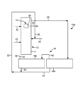
[00031] As shown in Figure 1, an ionic liquid catalyst reactor system 10a
that may be
used in accordance with the various embodiments of the present invention
includes a vessel
11 that comprises a reaction zone 12 and a heat exchange zone 14 inside of the
vessel 11 and
the reaction zone 12. In a preferred embodiment, the ionic liquid catalyst
reactor system 10a
is utilized for an alkylation reaction, and therefore the present invention
will be described in
.. relation to an alkylation reaction, with the understanding that the present
invention is not
necessarily limited to same and can be practiced in association with different
exothermic
reactions.
[00032] The reaction zone 12 preferably receives an iC4 hydrocarbon
stream 20. As
will be appreciated, other iso-paraffins may be utilized in accordance with
the present
invention. Additionally, an ionic liquid catalyst stream 22 is also passed
into the reaction
zone 12. Preferably, as shown, the ionic liquid catalyst stream 22 is combined
with the iC4
hydrocarbon stream 20. However, this is merely preferred. Finally, the
reaction zone 12 also
receives an olefin hydrocarbon stream 24 comprising C4 olefinic hydrocarbons.
The olefinic
hydrocarbon stream 24 can include iC4 hydrocarbons as well to dilute the
olefinic
hydrocarbons before entering the reaction zone 12 The overall concentration of
iC4
hydrocarbons in the reaction zone 12 is preferably well above the
stoichiometric requirement
of the alkylation reaction to minimize the side reactions of olefins with non-
iC4
hydrocarbons.
[00033] In the reaction zone 12, which is operated under proper
conditions, such as at a
temperature of between 20 to 30 C (68 to 86 F) under a pressure that keeps all
reactants and
catalysts in liquid phase, the olefinic hydrocarbons will react with the iC4
hydrocarbons to
form alkylated hydrocarbons, primarily i so-octane and other
trimethylpentanes. The liquids
within the vessel 11 of the reaction zone 12 will flow through the heat
exchange zone 14 of
the reaction zone 12.
- 7 -
CA 02981120 2017-09-26
WO 2016/205036 PCMJS2016/036405
[00034] In the heat exchange zone 14, a heat exchanger 30 will allow
for the transfer
of heat from the liquids in the vessel 11 (or in the reaction zone 12) to a
cooling fluid 32. The
supply and removal of the cooling fluid 32 is discussed in more detail below.
An effluent
stream 28 from the reaction zone 12 will be passed to a separation zone 16
having one or
more separation vessels 18a, 18b. In the first separation vessel 18a of the
separation zone 16,
the effluent stream 28 will be separated into a lighter hydrocarbon phase and
a heavier, ionic
liquid catalyst phase An ionic liquid catalyst stream 42 may be withdrawn and
recycled in
the processes, as is shown. Part of the ionic liquid catalyst may be
regenerated and then
recycled. Additionally, a hydrocarbon phase 40 may be withdrawn from the first
separation
vessel 18a and passed to a second separation vessel 18b.
[00035] In the second separation vessel 18b, the hydrocarbon phase
will be further
separated and provide a second ionic liquid catalyst stream 50. A hydrocarbon
product stream
52, in this case comprising an alkylate product, can be passed from the
separation zone 16 to
a fractionation column (not shown) or other separation unit to separate the
various
hydrocarbons in the product stream 52. In various embodiments, the amount of
ionic liquid in
the hydrocarbon product stream 52 is preferably less than 100 ppm, and more
preferably less
than 20 ppm. The alkylate product can be used as a fuel or fuel blending
component.
Although not depicted as such, entrained droplets of ionic liquid catalyst
within the
hydrocarbon phases in either separation vessel 18a, 18b may be further
separated with, for
example, a coalescing material, such as glass beads, fibers or electrostatic
separation devices.
[00036] Turning to Figure 2, in another embodiment, an ionic liquid
catalyst reactor
system 10b includes a plurality of reaction zones 12a, 12b, 12c, 12d each
including a reactor
22a, 22b, 22c, 22d. Preferably, the reaction zones 12a, 12b, 12c, 12d are
arranged in a series.
It should be appreciated that although not depicted as such, a single reactor
vessel could be
used with multiple separate reaction zones contained within the single vessel.
[00037] As shown in Figure 2, a heat exchange zone 14a is disposed outside
of the
reaction zones, for example, between the first reaction zone 12a and the
second reaction zone
- 8 -
CA 02981120 2017-09-26
WO 2016/205036 PCMJS2016/036405
12b. A second heat exchange zone 14b may also be disposed outside of a
reaction zone, for
example, between the second reaction zone 12b and the third reaction zone 12c.
This
alternating pattern of reaction zones12a, 12b and heat exchange zones 14a, 14b
may be
repeated such that a heat exchange zone is disposed between successive
reaction zones and
provide anionic liquid catalyst reactor system with a heat exchange zone being
disposed
outside of a reaction zone. A final heat exchange zone 14d may be disposed
between the last
reaction zone 12d and the separation zone 16 or may be omitted. Additional
heat exchangers
(not shown) may be placed before the first reaction zone 12a to cool the inlet
streams 20, 24
for maintaining the temperatures of the inlet streams and the fluid in the
first reaction zone in
desired levels.
[00038] In an exemplary embodiment, the iC4 hydrocarbon stream 20 and
the ionic
liquid catalyst stream 22 are passed to the first reaction zone 12a. As shown,
the ionic liquid
catalyst stream 22 is mixed with the iC4 hydrocarbon stream 20 prior to being
passed to the
first reactor vessel 22a. Once again, this is merely preferred. The olefin
hydrocarbon stream
24 comprising C4olefinic hydrocarbons is also passed into the first reaction
zone 12a. As with
the previous embodiment, the olefinic hydrocarbon stream 24 can include
iC4hydrocarbons as
well to dilute the olefinic hydrocarbons before entering the reactor vessel
22a. The overall
concentration of iC4hydrocarbons in the reactor vessel 22a is preferably well
above the
stoichiometric requirement of the alkylation reaction to minimize the side
reactions of olefins
with non- iC4hydrocarbons.
[00039] In the first reactor vessel 22a, which is operated under
proper conditions, such
as at a temperature of between 4.4 and 37.8 C (40 to 100 F) under a pressure
that keeps all
reactants and catalysts in liquid phase, the olefinic hydrocarbons will react
with the
iC4hydrocarbons to form al kyl ated hydrocarbons, primarily i so-octane and
other
trimethylpentanes. In order to mix the ionic liquid catalyst and the
hydrocarbons, the first
reaction zone 12a includes one or more impellers (not shown). The impeller(s)
may also
disperse the ionic liquid catalyst. The products of the reaction, excess
reactants (mainly iC4
hydrocarbons), and the ionic liquid catalyst are passed out of the first
reactor vessel 22a in an
effluent stream 28a.
- 9 -
CA 02981120 2017-09-26
WO 2016/205036 PCMJS2016/036405
1000401 The effluent stream 28a from the first reaction zone 12a is
passed to the first
heat exchange zone Ma. Each heat exchange zone 14a, 14b can include one or
more heat
exchangers 30. The heat exchangers 30 may comprise any style and form and may
have a
vertical, a horizontal or a tilted orientation. Within the first heat exchange
zone 14a, the
effluent 28a will be cooled via a cooling fluid 32 provided by a cooling fluid
circulation
system 34 (discussed in more detail below). As will be appreciated, the
cooling fluid 32 will
absorb heat from the effluent in the heat exchanger 30.
1000411 At least a portion cooled effluent stream 36a may be passed from
the first heat
exchange zone 14a to the second reaction zone 12b. The second reaction zone
12b will
receive iC4 hydrocarbons (and other hydrocarbons) from the cooled effluent
stream 36a, as
well as fresh hydrocarbons, for example from the olefin stream24. Again, as
shown part of
the iC4hydrocarbon stream 20 may be combined with the olefin stream 24 to
dilute the
concentration of olefins in stream 24 before it enters into the second
reaction zone 12b. The
second reaction zone 12b preferably operates in the same manner and under
similar
temperatures as the first reaction zone 12a and, thus will likewise produce an
effluent stream
28b containing more alkylate components than effluent stream 28a.
1000421 The effluent stream 28b from the second reaction zone 12b will be
passed to
the second heat exchange zone 14b, comprises one or more heat exchanges 30
which also
receive the cooling fluid 32. A cooled effluent stream 36b from the second
heat exchange
zone 14b may be passed to a third reaction zone 12c, and so on and so forth.
1000431 A net effluent stream 38, comprising hydrocarbons and ionic liquid
catalyst,
may be passed to the separation zone 16 to be separated into a lighter
hydrocarbon phase
52and a heavier, ionic liquid catalyst phase 50. In the separation zone 16,
entrained droplets
of ionic liquid catalyst within the hydrocarbon phase may be further
separated, for example
with a coalescing material, such as glass beads, fibers or electrostatic
separation devices. The
ionic liquid catalyst stream 50 comprising ionic liquid catalyst separated in
the separation
zone 16 can be returned to the reaction zones 12a, 12b. A hydrocarbon product
stream 52, in
- 10 -
CA 02981120 2017-09-26
WO 2016/205036 PCMJS2016/036405
this case comprising an alkylate product, can be passed from the separation
zone 16 to a
fractionation column (not shown) or other separation unit to separate the
various
hydrocarbons in the product stream 52.
[00044] As mentioned above, maintaining a proper temperature of the cooling
fluid 32
passed to the heat exchanges zones 14a, 14b is important for a variety of
reasons, including,
controlling the temperature within the reaction zones 12a, 12b, increasing the
product yield,
and maintaining product quality. Additionally, it is desirable to maintain a
certain velocity or
rate of cooling fluid though the heat exchangers 30 in the heat exchanges
zones 14a, 14b. In
a preferred embodiment, the temperature of the cooling fluid is between -6.7
to 26.7 C (20
to 80 F), or between 1.7 and 12.8 C (35 to 55 F). Accordingly, as shown in
Figures 3 and
4, preferred cooling fluid circulation systems 34 are shown.
[00045] In Figure 3, the cooling fluid circulation system 34 includes
a chiller 100 and a
reservoir 102. The chiller 100 will cool the cooling fluid, such as water or a
mixture of glycol
and water, to a desired temperature and at a desired rate. The cooling fluid
is passed from the
chiller 100 to the reservoir102 at first flow rate. A stream 104 of cooling
fluid may be
withdrawn from the reservoir 102. The stream 104 of cooling fluid withdrawn
from the
reservoir 102 is passed to a heat exchange zone 114, such as the heat exchange
zones 14, 14a,
14b shown in Figures 1 and 2. In the heat exchange zone 114, the cooling fluid
will absorb
heat from a process fluid 128, such as the effluent streams 28a, 28b shown in
Figure 2 or the
liquid within the vessel 11 of Figure 1. A heated cooling fluid 106 may be
passed back to the
chiller 100 and a cooled process fluid 136 may comprise the cooled effluent
streams 36a, 36b
described above with reference to Figure 2 or the effluent stream 28 shown in
Figure 1.
[00046] It is preferable to adjust the flow rate of the stream 104 of
cooling fluid
through the heat exchange zone 114, accordingly a probe 108, such as a
temperature sensor,
thermocouple or the like, is configured to measure (or determine) the
temperature of the
cooled process fluid 136. The probe 108 may be in communication with a valve
110
.. configured to adjust the flow through a line based upon the measured
temperature. However,
since maintaining a minimum flow rate through the heat exchange zone 114 is
desirable, the
-11-
valve 110 is disposed in a bypass line 112 which does not pass through the
heat exchange zone
114 (or any of the heat exchange zones 14, 14a, 14b). It is understood, that
the bypass line 112
could be used to cool some other process stream, but not the heat exchange
zones 14a, 14b in
the ionic liquid catalyst reactor system 10. The rate of flow through the
bypass line 112 will
adjust based upon the temperature of the cooled process fluid 136. This, in
turn, will ensure
that the flow through the heat exchange zone 114is at a desired level to
obtain the desired
cooling.
[00047] Turning to Figure 4, in another cooling fluid circulation
system 34, a second
reservoir 116 is provided, in addition to the chiller 100 and first reservoir
102. The second
reservoir 116 is configured to receive heated cooling fluid 106 from the heat
exchange zone
114 and is further configured to recycle part of cooling fluid 140 in the
second reservoir 116
back to the first reservoir 102 so that the stream 104 may be withdrawn at a
second flow rate
to the heat exchange zone 1 14 that may be greater than the first flow rate to
keep certain
cooling fluid velocity through the heat exchange zone 114. The second
reservoir 116 may also
be also configured to receive cooling fluid from the bypass line 112.
1000481 Additionally, in comparison to the embodiment shown in Figure
3, in Figure 4,
the cooling fluid circulation system 34 also includes a chiller loop 120
configure to circulate
cooling fluid back to the chiller 100 without passing to the reservoir 102 or
the heat exchange
zone 114. A second valve 122 may be disposed between the chiller loop 120 and
the reservoir
102, and is preferably in communication with the sensor or probe 108 so that
the valve 122 will
adjust the flow of cooling fluid passed to the reservoir 102 if the
temperature of the cooled
process fluid 136 cannot be controlled by the valve on bypass line 112 only.
This will ensure
that the flow through the heat exchange zone 114 is sufficient to maintain the
cooled process
fluid 136 near the desired temperature.
[00049] The cooling fluid circulation systems 34 depicted in Figures 3
and 4 are merely
preferred.
- 12 -
CA 2981120 2019-03-27
CA 02981120 2017-09-26
WO 2016/205036 PCMJS2016/036405
[00050] By providing a cooling fluid system that operates
independently of the
temperature of the cooling fluid from a cooling tower, a proper flow rate and
temperature
may be maintained within the heat exchange zones to ensure that the process
fluid is cooled
to the desired level even when the reaction process fluid temperature or flow
rates are
changed. Maintaining control of the temperature in the process fluid will
reduce the impact of
the heat exchange zone on the alkylate product.
[00051] It should be appreciated and understood by those of ordinary
skill in the art
that various other components such as valves, pumps, filters, coolers, mixing
and coalescing
devices, etc. were not shown in the drawings as it is believed that the
specifics of same are
well within the knowledge of those of ordinary skill in the art and a
description of same is not
necessary for practicing or understanding the embodiments of the present
invention.
SPECIFIC EMBODIMENTS
[00052] While the following is described in conjunction with specific
embodiments, it
will be understood that this description is intended to illustrate and not
limit the scope of the
preceding description and the appended claims.
[00053] A first embodiment of the invention is a process for
controlling a flow of a
cooling fluid through a heat exchanger, the process comprising passing a
cooling fluid from a
chilling zone to a reservoir; passing a first portion of the cooling fluid
from the reservoir
through a heat exchange zone; passing a second portion of the cooling fluid
from the
reservoir through a bypass line around the heat exchange zone; passing a
process fluid
through the heat exchange zone; and, absorbing heat from the process fluid
with the cooling
fluid in the heat exchange zone to provide a cooled process fluid. An
embodiment of the
invention is one, any or all of prior embodiments in this paragraph up through
the first
embodiment in this paragraph for comprising adjusting the second portion of
the cooling
fluid from the reservoir that flows through a bypass line based upon a
temperature of the
cooled process fluid. An embodiment of the invention is one, any or all of
prior embodiments
in this paragraph up through the first embodiment in this paragraph wherein a
temperature of
the first portion of the cooling fluid from the reservoir is between 6.7 and
26.7 C (20 to
80 F). An embodiment of the invention is one, any or all of prior embodiments
in this
- 13 -
CA 02981120 2017-09-26
WO 2016/205036 PCMJS2016/036405
paragraph up through the first embodiment in this paragraph wherein a
temperature of the
first portion of the cooling fluid from the reservoir is between L7 and 12.8
C (35 to 55 F).
An embodiment of the invention is one, any or all of prior embodiments in this
paragraph up
through the first embodiment in this paragraph wherein the heat exchange zone
comprises a
plurality of heat exchangers. An embodiment of the invention is one, any or
all of prior
embodiments in this paragraph up through the first embodiment in this
paragraph wherein a
first heat exchanger from the plurality of heat exchangers receives a process
fluid from a first
reaction zone, and wherein a second heat exchanger from the plurality of heat
exchangers
receives a process fluid from a second reaction zone different than the first
reaction zone. An
embodiment of the invention is one, any or all of prior embodiments in this
paragraph up
through the first embodiment in this paragraph wherein the heat exchange zone
is disposed
within a reaction zone. An embodiment of the invention is one, any or all of
prior
embodiments in this paragraph up through the first embodiment in this
paragraph wherein
only a first portion of the cooling fluid is passed from the chilling zone to
the reservoir, and
the process further comprising recirculating a second portion of the cooling
fluid in a
recirculation loop.
1000541 A second embodiment of the invention is a process for cooling
fluid
circulation system comprising a chiller configured to provide cooling fluid, a
reservoir
configured to receive the cooling fluid and to provide at least one cooling
stream, the
reservoir in communication with a cooling fluid inlet of at least one heat
exchanger in at least
one heat exchange zone, the at least one heat exchange zone disposed between a
first reaction
zone and a second reaction zone; a bypass line configured to pass cooling
fluid around the at
least one heat exchange zone and return the cooling fluid to the chiller
without passing
through the at least one heat exchanger in the at least one heat exchange
zone. An
embodiment of the invention is one, any or all of prior embodiments in this
paragraph up
through the second embodiment in this paragraph further comprising a chiller
loop
configured to circulate a portion of cooling fluid back to the chiller. An
embodiment of the
invention is one, any or all of prior embodiments in this paragraph up through
the second
embodiment in this paragraph further comprising a second reservoir configured
to receive
cooling fluid from the at least one heat exchanger in the at least one heat
exchange zone and
- 14 -
CA 02981120 2017-09-26
WO 2016/205036 PCMJS2016/036405
further configured to provide cooling fluid to the chiller. An embodiment of
the invention is
one, any or all of prior embodiments in this paragraph up through the second
embodiment in
this paragraph, wherein the second reservoir is also configured to receive
cooling fluid from
the bypass line. An embodiment of the invention is one, any or all of prior
embodiments in
this paragraph up through the second embodiment in this paragraph further
comprising at
least one valve disposed in the bypass line configured to adjust an amount of
cooling fluid
passing there through. An embodiment of the invention is one, any or all of
prior
embodiments in this paragraph up through the second embodiment in this
paragraph further
comprising a probe configured to determine a temperature of a process fluid
exiting the at
least one heat exchanger in the at least one heat exchange zone disposed
between the first
reaction zone and the second reaction zone, the temperature probe being in
communication
with the at least one valve disposed in the bypass line. An embodiment of the
invention is
one, any or all of prior embodiments in this paragraph up through the second
embodiment in
this paragraph further comprising at least one valve disposed between the
reservoir and the
.. chiller and configured to adjust an amount of cooling fluid passed to the
reservoir from the
chiller. An embodiment of the invention is one, any or all of prior
embodiments in this
paragraph up through the second embodiment in this paragraph wherein the at
least one valve
disposed between the reservoir and the chiller is in communication with the
temperature
probe.
1000551 A third embodiment of the invention is a process for
controlling a flow of a
cooling fluid through a heat exchanger, the process comprising cooling a fluid
to a desired
temperature in a chilling zone; passing the fluid from the chilling zone to a
reservoir at a first
flow rate; passing a fluid from the reservoir through a heat exchange zone at
a second flow
rate; removing heat from a process fluid with the fluid from the reservoir in
the heat exchange
zone to provide a heated fluid and a cooled process fluid; passing the heated
fluid back to the
chilling zone; and, adjusting at least one of the first flow rate and the
second flow rate based
upon a temperature of the cooled process fluid. An embodiment of the invention
is one, any
or all of prior embodiments in this paragraph up through the third embodiment
in this
paragraph further comprising passing a fluid from the reservoir around the
heat exchange
zone via a bypass line at a third flow rate. An embodiment of the invention is
one, any or all
CA 02981120 2017-09-26
WO 2016/205036 PCMJS2016/036405
of prior embodiments in this paragraph up through the third embodiment in this
paragraph
wherein a sum of the third flow rate and the second flow rate is greater than
the first flow
rate An embodiment of the invention is one, any or all of prior embodiments in
this
paragraph up through the third embodiment in this paragraph wherein a sum of
the third flow
rate and the second flow rate is equal to the first flow rate
1000561 Without further elaboration, it is believed that using the
preceding description
that one skilled in the art can utilize the present invention to its fullest
extent and easily
ascertain the essential characteristics of this invention, without departing
from the spirit and
scope thereof, to make various changes and modifications of the invention and
to adapt it to
various usages and conditions. The preceding preferred specific embodiments
are, therefore,
to be construed as merely illustrative, and not limiting the remainder of the
disclosure in any
way whatsoever, and that it is intended to cover various modifications and
equivalent
arrangements included within the scope of the appended claims.
1000571 In the foregoing, all temperatures are set forth in degrees Celsius
and, all parts
and percentages are by weight, unless otherwise indicated.
16