Note: Descriptions are shown in the official language in which they were submitted.
FLEXIBLE MOUNTING SYSTEM FOR HAND HYGIENE DISPENSERS
CROSS-REFERENCE TO RELATED APPLICATION
[0001] This application claims the benefit of U.S. Application No. 62/141,629,
titled,
"FLEXIBLE MOUNTING SYSTEM FOR HAND HYGIENE DISPENSERS," filed April
1, 2015.
BACKGROUND
[0002] Product dispensers are used for a variety of purposes and for a variety
of
applications. For example, hand hygiene product dispensers are often used in
health care
and food service settings to reduce pathogen transmission that may lead to the
spread of
illness. Compliance with hand hygiene guidelines is considered the most
effective action
health care workers can take to reduce pathogen transmission in health care
settings. To
facilitate compliance with hand washing procedures, hand hygiene product
dispensers
should be readily available so that hand washing is easy and convenient. For
example,
hand hygiene products, such as liquid, foam, or gel hand washing soaps, may be
placed
near sinks or other hand washing stations in a healthcare or restaurant
setting to facilitate
hand washing. Other types of hand hygiene products, such as waterless hand
sanitizers,
may also be placed in and around healthcare or restaurant settings. However,
the wide
variety of environments in which such dispensers are used means that mounting
of the
dispenser in a convenient location may sometimes be difficult.
SUMMARY
[0003] In general, the disclosure provides a product dispenser mounting system
including
a dispenser holder and at least one mounting apparatus. The dispenser holder
may be
attached to the mounting apparatus by means of a releasable connection
mechanism. In
some examples, the releasable connection mechanism provides for attachment of
the
dispenser holder to the mounting apparatus in multiple orientations. In one
example, the
mounting apparatus includes a mounting bracket configured for mounting to a
support
object, such as a wall, table, or counter top, cabinet, shelf, cart, etc. In
another example,
the mounting apparatus includes a mounting clamp configured for mounting to
ledges,
poles, bedrails, handles, etc.
[0004] In one example, the disclosure is directed to a system comprising a
product
dispenser mounting system comprising a dispenser holder, the dispenser holder
including
1
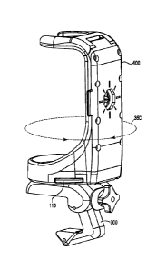
Date recue/Date received 2023-03-17
a dispenser holder body configured to receive a product dispenser, the
dispenser holder
body further including a sidewall having a front surface and a back surface
and a back
plate positioned proximate the back surface of the sidewall, the back plate
further
including a first aperture, and a latch positioned between the back plate and
the back
.. surface of the sidewall, the latch including a second aperture, the walls
of the second
aperture defining a locking side and an unlocking side, the latch further
moveable between
a first locked position and a second unlocked position, and a mounting
apparatus
configured for fixedly mounting on a support object, the mounting apparatus
including an
attachment post including a base portion having a shape configured to fit
within the first
.. aperture of the back plate in one or more orientations, and a post portion
extending
outwardly from the base portion and including a cap, the cap having a diameter
that is
relatively larger than a diameter of the post portion, the cap further
providing a bottom
locking surface, such that when the base portion of the attachment post is fit
within the
first aperture of the back plate, the walls of the second aperture defining
the locking side
.. engage the bottom locking surface of the cap when the latch is moved into
the first locked
position.
[0005] The mounting apparatus may include a mounting bracket or a mounting
clamp.
The product holder may be configured to hold a manual pump bottle, a trigger
sprayer
bottle, a pump sprayer, a pressure sprayer, a canister, or a container that
dispenses or
contains cleansing or sanitizing wipes.
[0006] The system may further include a sensor that detects actuation of the
product
dispenser, and an indicator that is activated in response to each detected
actuation of the
product dispenser. The system may further include a sensor that detects
actuation of the
product dispenser, and a counter that increments a count in response to each
detected
actuation of the product dispenser. Data associated with the detected
actuations of the
product dispenser may be received and analyzed by a hand hygiene compliance
computing
system.
[0007] In another example, the disclosure is directed to a product dispenser
mounting
system comprising a dispenser holder configured to support a product
dispenser, the
dispenser holder having a back side and a bottom side, one or more connector
clips, each
of the one or more connector clips integrated into one of the back side or the
bottom side
of the dispenser holder, each connector clip including a first sidewall
including a first
aperture, a release latch including a second aperture, the release latch
moveable from a
first unlocked position to a second locked position with respect to the first
aperture, the
2
Date recue/Date received 2023-03-17
release latch further providing a locking surface on a side facing the first
sidewall, a
mounting apparatus configured for fixedly mounting on a support object and
including an
attachment post configured for releasable connection to the one or more
connector clips,
the attachment post including a base portion having a shape configured to fit
within the
first aperture of the first sidewall in one or more orientations, and a post
portion including
a cap providing a bottom locking surface that engages with the locking surface
of the
release latch when the base portion of the mounting apparatus is fit within
the first
aperture and the release latch is in the second locked position.
[0008] The one or more connector clips may include a first connector clip
integrated in the
back side of the dispenser holder and a second connector clip integrated in
the bottom side
of the dispenser holder.
[0009] The details of one or more examples are set forth in the accompanying
drawings
and the description below. Other features will be apparent from the
description and
drawings.
BRIEF DESCRIPTION OF DRAWINGS
[0010] FIG. 1A is a front perspective view of an example dispenser holder in
accordance
with one or more aspects of the present disclosure, and FIG. 1B is a front
perspective view
of the example dispenser holder of FIG. 1A and including an example product
dispenser.
[0011] FIG. 2A is an exploded perspective view of the example dispenser holder
of FIG.
1; FIG. 2B is a back perspective view of the sidewall of the example dispenser
holder of
FIG. 2A; FIGS. 2C and 2D are top and bottom views of an example release tab.
[0012] FIGS. 3A-3B are perspective views of a top portion of the example
dispenser
holder of FIGS. 1 and 2, showing the first and second arms at a first, lowered
position
.. (FIGS. 3A) and at a second, raised position (FIG. 3B).
[0013] FIGS. 3C-3D are cross-sectional side views of a top portion of the
example
dispenser holder of FIGS. 1 and 2, showing the first and second arms at a
first, lowered
position (FIGS. 3C) and at a second, raised position (FIG. 3D).
[0014] FIG. 4 is a back perspective view of the example dispenser holder of
FIGS. 1 and
2.
[0015] FIG. 5 is a perspective view of an example mounting bracket in
accordance with
one or more aspects of the present disclosure.
[0016] FIG. 6 is a perspective view of an example mounting clamp in accordance
with one
or more aspects of the present disclosure.
3
Date recue/Date received 2023-03-17
[0017] FIG. 7 is a perspective view of an example dispenser holder of FIGS. 1
and 2
attached to the example mounting clamp of FIG. 6.
[0018] FIG. 8 is an interior view illustrating the fitting of an example
mounting bracket
200 and back plate 126 of an example dispenser holder.
[0019] FIG. 9 is a side cross-sectional view of an example dispenser holder
releasably
connected to an example mounting clamp.
[0020] FIG. 10 is a perspective diagram of the lower portion of another
example
dispenser holder configured for electronic sensing of dispenser actuations.
[0021] FIG. 11 is a cross-sectional side view of the example dispenser holder
of FIG. 10.
[0022] FIG. 12 is a block diagram of an example electronic sensor module and
an
environment in which the sensor module may be used to communicate data
concerning
product dispenser actuations.
[0023] FIGS. 13A-13C show an example mounting bracket mounted to various
support
objects.
[0024] FIGS. 14A-14D are various views showing another example mounting
bracket;
FIGS. 14E-14G show the mounting bracket of FIGS. 14A-14D and another example
dispenser holder.
[0025] FIGS. 15A-15E show another example of a mounting bracket; FIGS. 15F-15I
show
the mounting bracket of FIGS. 15A-15E and another example dispenser holder.
[0026] FIGS. 16A-16C show another example of a mounting bracket; FIGS. 16D-16F
show the mounting bracket of FIGS. 16A-16C and another example dispenser
holder.
[0027] FIGS. 17A-17C show an example product dispenser being loaded into an
example
dispenser holder.
[0028] FIGS. 18A-18C show an example product dispenser being loaded into
another
example dispenser holder.
[0029] FIG. 19 shows another example product holder.
[0030] FIGS. 20A-20C show other example product holders.
[0031] FIGS. 21A and 21B show another example mounting apparatus and latch.
[0032] FIG. 22 shows another example mounting apparatus and latch.
[0033] FIGS. 23A and 23B show another example mounting apparatus and latch.
[0034] FIGS. 24A and 24B show another example product holder.
[0035] FIGS. 25A and 25B show another example product holder.
4
Date recue/Date received 2023-03-17
DETAILED DESCRIPTION
[0036] In general, the disclosure provides a product dispenser mounting system
including
a dispenser holder and at least one mounting apparatus. The dispenser holder
may be
attached to the mounting apparatus by means of a releasable connection
mechanism. The
releasable connection mechanism provides for attachment of the dispenser
holder to the
mounting apparatus in multiple orientations. In one example, the mounting
apparatus
includes a mounting bracket configured for mounting to a substantially flat
surface, such
as a wall, table, or counter top, cabinet, shelf, etc. In another example, the
mounting
apparatus includes a mounting clamp configured for mounting to ledges, poles,
bedrails,
handles, etc.
[0037] The product dispenser mounting system described herein may provide
several
advantages. For example, the product dispenser mounting system provides
flexible
options for mounting of a product dispenser in a wide variety of environments
and on a
wide variety of support objects. As another example, the product dispenser
mounting
system in accordance with the present disclosure is low profile and designed
to comply
with relevant state and federal regulations such as the 2010 ADA Standards for
Accessible
Design (e.g., that objects may not protrude more than 4 inches (100 mm)
horizontally into
the circulation path.
[0038] Referring now to FIGS.1A-1B, and 2A, FIG. 1A is a perspective view of
an
.. example dispenser holder 100 in accordance with one or more aspects of the
present
disclosure. FIG. 1B is a front perspective view of the example dispenser
holder of FIG.
TA and including an example product dispenser 101 in the foun of a manual pump
bottle.
FIG. 2A is an exploded perspective view of the dispenser holder 100 of FIG.
1A. In the
examples described herein, product dispenser 101 is shown and described as
being a
manual pump bottle; however, it shall be understood that the dispenser holders
described
herein may be adapted for any type of product dispenser, including manual pump
bottles,
trigger sprayers, pump sprayers, pressure sprayers, canisters, containers that
dispense or
contain cleansing or sanitizing wipes, or any other type of product dispenser,
and that the
disclosure is not limited in this respect.
[0039] Dispenser holder 100 includes a dispenser holder body 108 including a
sidewall
112, a top portion 120, and a bottom portion 124. A front side of sidewall 112
may be
concave to at least partially receive a product dispenser, such as the bottle
portion of a
manual pump-type product dispenser, as shown in FIG. 1B, so as to provide a
lower
profile in the horizontal direction when dispenser holder 100 is mounted to a
support
5
Date recue/Date received 2023-03-17
object. Top portion 120 includes first and second arms 102A and 102B,
respectively,
extending outwardly relative to sidewall 112 of dispenser body 108. In this
example, first
and second arms 102A and 102B curve inwardly toward the center of dispenser
holder 100
to form a generally C-shaped collar forming a receiving area 106. Receiving
area 106 is
sized to receive at least a portion of product dispenser 101, such as the neck
of a manual
pump bottle containing a hand hygiene product. Top portion 120 is pivotally
connected to
the sidewall 112 of dispenser holder body 108 by means of a hinge 104 to
permit raising
and lowering of first and second arms 102A and 102B between a first, lowered
position
(as shown in FIGS. 1A and 1B) and a second, raised position. In the first,
lowered
position, arms 102A and 102B secure a product dispenser within dispenser
holder 100.
When in the second, raised position, arms 102A and 102B permit removal from
and/or
replacement of a product dispenser into the dispenser holder 100.
[0040] A base 118 is sized to fit within interior sidewalls 128 of bottom
portion 124 and is
configured to support a product dispenser installed in dispenser holder 100.
When
properly installed into dispenser holder 100, a product dispenser, such as a
manual pump
bottle, is held in position by first and second arms 102A and 102B, interior
sidewalls of
base portion 124, and base plate 118. One or more removable shims that fit
within the
collar formed by first and second arms 102A and 102B may also be included to
provide a
good fit for multiple sizes or types of product dispensers. Base 118 may also
be sized
and/or shaped so as to fit one or more different sizes or shapes of product
dispensers, or
multiple bases may be provided, each configured to hold a differently sized or
shaped
product dispenser.
[0041] Dispenser holder body 108 may be adapted to hold various types of
product
dispensers, and the size and shape of the dispenser holder body may be changed
to suit
those various types of product dispensers, including manual pump bottles,
trigger sprayer
bottles, pump sprayers, pressure sprayers, canisters, containers that dispense
or contain
cleansing and/or sanitizing wipes, etc., and it shall be understood that the
disclosure is not
limited in this respect.
[0042] Example dispenser holder 100 further includes a back plate 126 adapted
to be
attached to a back side 110 of sidewall 112. The attachment may be by screws,
snap-fit,
or other attachment mechanism. In other examples, back plate 126 may be
integrally
molded with the sidewall 112 to form a single piece. Likewise, a base plate
134 is adapted
to be attached to a bottom side 150 of dispenser holder 100. In this example,
base plate
134 fits within bottom portion 124 and may be held in place by means of
screws, snap-fit,
6
Date recue/Date received 2023-03-17
tongue and groove, adhesive, ultrasonic welding, or other means of attachment
to the back
plate 126.
[0043] Both back plate 126 and base plate 134 include an aperture 130, 140,
respectively.
Each aperture 130, 140 forms part of a releasable connection mechanism by
which
dispenser holder 100 may be connected to a mounting apparatus. In this way, a
mounting
apparatus may be connected to the back of dispenser holder 100 or to the
bottom of
dispenser holder 100. In the examples shown and described herein, apertures
130 and 140
are generally octagon-shaped. The octagonal shape of apertures 130 and 140
permits
attachment of dispenser holder 100 to a mounting apparatus in multiple
orientations, in
.. this example at 45 degree intervals, as will be described herein further
below. It shall be
understood, however, that apertures 130 and/or 140 may be any n-sided
geometric shape,
including any regular n-sided polygon, such as a triangle, a square, a
rectangle, a
pentagon, a hexagon, an octagon, a star polygon, or any other geometry, such
as a clover-
leaf shape, wheel locks, and that the disclosure is not limited in this
respect.
[0044] Release tabs 114 and 116 fit within slots 136 and 138, respectively,
which are
formed when dispenser holder 100 is fully assembled. Release tab 114 includes
an
asymmetrical aperture 178 having a first, narrow end 173 and a second, wider
end 171
(see FIGS. 2C and 2D). Similarly, release tab 116 includes an asymmetrical
aperture 180
having a first, narrow end and a second, wider end.
[0045] Release tabs 114 and 116 slide along and are retained by guide rails
164 and 166,
respectively. Back plate 126 and base plate 134 may include posts 170 and 172,
respectfully, each of which may receive one side of a spring when the
dispenser holder is
fully assembled (springs not shown in FIG. 2A). The other side of these
springs may be
received by posts 174 and 176 of release tabs 114 and 116, respectively. When
assembled, depression of one of release tabs 114 or 116 releases the dispenser
holder from
the releasable connection to the mounting apparatus. For example, when the
back of
dispenser holder is connected to a mounting apparatus, the connection may be
released
using release tab 114. When the bottom of dispenser holder is connected to a
mounting
apparatus, the connection may be released using release tab 116. Further
details
concerning the releasable connection mechanism in accordance with one or more
aspects
of the present disclosure are described herein further below. The function of
the springs
on release tabs 114, 116 may also be implemented by taking advantage of the
elastic
properties of plastic by providing a molded flexible member implemented during
the
injection molding process.
7
Date recue/Date received 2023-03-17
[0046] FIG. 2B is a perspective view illustrating the back surface 110 of
sidewall 112 and
the bottom surface 119 of base plate 118. Back surface 110 includes an
alignment
projection 154 and bottom surface of base plate 118 includes a tapered
projection 144.
Each projection 154 and 144 includes a tapered tip 155, 145 and a tapered base
section
157, 147, respectively. For each projection 154, 144, the diameter of the base
157, 147, is
relatively wider than the diameter of the tip 155, 145. In this example,
projections 154 and
144 further include one or more vanes 153, 143; however, it shall be
understood that
projections 154 and 144 may also be smoothly sided, and that that disclosure
is not limited
in this respect. The purpose of tapered projections 154, 144 is to help guide
and align the
mating halves of the releasable connection as the dispenser holder 100 is
loaded onto a
mounting apparatus, as further described herein below.
[0047] FIGS. 2C and 2D are top and bottom views, respectively, of an example
release
tab, such as release tab 114. It shall be understood that any other release
tabs on dispenser
holder 100, such as release tab 116, may have the same design specifications
as those
.. shown in FIGS. 2A, 2C, and 2D. Example release tab 114 includes a top
surface 121, a
bottom surface 123, aperture 178, and post 174. Aperture 178 is asymmetrical
in the sense
that aperture 178 includes a first, wider side 171 that is relative wider than
a second,
narrower side 173. On the bottom surface 123 of release tab 114, a tapered
wall 115 is
provided around at least a portion of the perimeter of aperture 178. On the
top surface 121
of release tab 114, a locking edge 117 is provided on at least a portion of
the
circumference on second, narrower side 173 of aperture 178. Tapered wall 115
and
locking edge 117 cooperate with a mating half of the releasable connection to
provide for
auto-loading of the dispenser holder onto a mounting apparatus, as further
described
herein below.
[0048] FIGS. 3A-3B are perspective views of top portion 120 of dispenser
holder 100.
Specifically, FIGS. 3A-3B are perspective views of a top portion 120 of the
dispenser
holder 100 of FIGS. 1 and 2, showing the first and second arms 102A and 102B
at a first,
lowered position (FIGS. 3A) and at a second, raised position (FIG. 3B). FIGS.
3C-3D are
cross-sectional side views of top portion 120 of the dispenser holder 100 of
FIGS. 1 and 2,
.. showing the first and second aims 102A and 102B at a first, lowered
position (FIGS. 3C)
and at a second, raised position (FIG. 3D). As may be seen in FIGS. 3C and 3D,
hinge
104 further includes a first hinge section 184 forming a piece with sidewall
112 and back
plate 126 and a second hinge section 186 forming a piece with top portion 120.
First
hinge section 184 includes two detents 182A and 182B. Detent 182A is
associated with
8
Date recue/Date received 2023-03-17
top portion 120 in the first, lowered position. Detent 182B is associated with
top portion
120 in the second, raised position. Second hinge section 186 includes a
flexible tab 180
sized to fit within detents 182A and 182B. Interaction between flexible tab
180 and detent
182A or 182B provides positive stopping locations for the lowered (182A) and
raised
(182B) positions, and also retains the top portion 120 in either the lowered
or raised
position. Thus, interaction between flexible tab 180 and detent 182B holds top
portion
120 in the second, raised position for product dispenser bottle removal and
replacement.
Interaction between flexible tab 180 and detent 182A holds top portion 120 in
the first,
lowered position, thus helping to retain product dispenser within dispenser
holder 100.
[0049] FIG. 4 is a back perspective view of the example dispenser holder 100
of FIGS. 1
and 2. Dispenser holder 100 includes a back side 190 and a bottom side 150.
This view
illustrates that, when assembled, the back side surface 110 of sidewall 112
(see FIG. 2) is
visible through aperture 130 of back plate 126. Projection 154 is also visible
through
aperture 130 of back plate 126. Projection 154 extends outwardly from the back
side
surface 110 of sidewall 112 and is substantially concentrically aligned with
aperture 130.
Projection 154 and aperture 130 comprise a first connector clip indicated
generally by
reference numeral 192. First connector clip 192 is configured to releasably
connect with a
corresponding mating attachment post provided by a mounting apparatus, as
shown and
described below.
[0050] Similarly, the bottom surface 142 of base 118 (see FIG. 2) is visible
through
aperture 140 of base plate 134. Projection 144 is also visible through
aperture 140 of base
plate 134. Projection 154 extends outwardly from the bottom surface 142 of
base 118 and
is aligned substantially in the center of aperture 140. Aperture 140 and
projection 154
comprise a second connector clip indicated generally by reference numeral 194.
As with
first connector clip 192, second connector clip 194 is configured to
releasably connect
with a corresponding mating attachment post provided by a mounting apparatus,
as shown
and described below.
[0051] First connector clip 192 and second connector clip 194 thus provide
alternative
connection options that provide flexibility in mounting of the dispenser
holder in a wide
variety of environments. For example, dispenser holder may be mounted on a
support
object, such as a wall, cabinet, pole, post, or other substantially vertical
support object
using first connector clip 192. As another example, dispenser holder 100 may
be mounted
on a counter, shelf, medical cart, table, or other substantially horizontal
support object
using second connector clip 194. In addition, the octagonal geometry of
apertures 130 and
9
Date recue/Date received 2023-03-17
140 provide for rotatable mounting of dispenser holder at 45 degree intervals,
as further
described herein below, thus allowing dispenser holder 100 to be mounted on
support
objects that are not substantially vertical or horizontal while still
maintaining the dispenser
holder in an upright position for dispensation of the product.
[0052] FIG. 5 is a perspective view of an example mounting bracket 200 in
accordance
with one or more aspects of the present disclosure. Mounting bracket 200
includes a base
plate 202 and an attachment post indicated generally by reference numeral 210.
In this
example, base plate 202 includes one or more screw holes 206A-206D for screw
mounting
the mounting bracket 200 to a support object, such as a wall, table, counter,
cabinet, or
other substantially flat surface. Base plate 202 also includes one or more
channels 204A-
204B by which mounting bracket 200 may be attached to a support object using
one or
more cable or zip ties, straps or other type of mechanical fastener. Mounting
bracket 200
may also be adhesively mounted to any substantially flat surface.
[0053] Base plate 202 may also include one or more hinges that peimit mounting
bracket
200 to conform to additional contoured surfaces, such as around corners or on
rounded
surfaces. The hinges may be, for example, a thin flexible hinge or flexible
bearing made
from the same material as the base plate 202. The hinge may be a living hinge
produced
in an injection molding operation that creates the hinge and the base plate
202 at one time
and as a single piece. For example, base plate 202 may be thinned or cut along
one or
more of channels 204 to allow the rigid sections of base plate 202 to bend
along the line of
the hinge. In another example, the hinge may be formed of some other flexible
substance
and attached to the pieces of the base plate 202 in the desired location to
form a
conformable mounting bracket 200.
[0054] Attachment post 210 includes a base portion 212 and a post portion 214.
Post
portion 214 further includes a cap 215 and a shaft extending from the cap and
defining a
center longitudinal axis 260 for the attachment post 210. A top side of cap
215 includes a
tapered edge 211 and a bottom side of cap 215 provides a locking surface 217.
In this
example, base portion 212 includes tapered shoulders 221 and has complementary
geometry to the geometry of apertures 130/140. In some examples, the base
portion 212
may have the same general geometry as apertures 130/140. To that end, in this
example,
base portion 212 is substantially octagonal in shape. In general, base portion
212 is sized
and shaped to fit within apertures 130 and 140 of dispenser holder 100 such
that dispenser
holder 100 may be not be rotated around the longitudinal axis 260 once the
dispenser
holder is loaded onto attachment post 210. As discussed above, although
apertures 130
Date recue/Date received 2023-03-17
and 140 and base portion 212 of attachment post are described as being
octagonal in
shape, it shall be understood, however, that apertures 130 and/or 140 and base
portion 212
of attachment post 210 may be any n-sided geometric shape, including any
regular n-sided
polygon, such as a triangle, a square, a rectangle, a pentagon, a hexagon, an
octagon, a star
polygon, or any other shape, such as clover-leaf shape, wheel lock or any
other geometry,
and that the disclosure is not limited in this respect. In addition, although
the apertures
and attachment posts are shown in these examples as having the same geometry,
they may
have different but complementary geometries, and again the disclosure is not
limited in
this respect. In some examples, complementary geometries include geometries
that are
sized and shaped to fit within one another and provide the locking function in
one or more
orientations as described herein.
[0055] Base portion 212 and post portion 214 may be integrally molded with
base plate
202 to form a single piece. Attachment post 210 further includes a bore 222
extending
through the center longitudinal axis 260 of base portion 212 and post portion
214, and in
this example also extends through base plate 202. Bore 222 is sized to receive
one of
projections 144 and 154 of connector clips 194 and 192, respectively. As
mentioned
above, octagonal base portion 212 and octagonal apertures 130, 140 provide for
mounting
of dispenser holder 100 at 45 degree intervals without repositioning of
mounting bracket
200. This helps to provide flexible mounting options for the dispenser holder
on a wide
variety of support objects.
[0056] FIG. 6 is a perspective view of an example mounting clamp 300 in
accordance
with one or more aspects of the present disclosure. Mounting clamp 300
includes a first
jaw 302 having a first inward clamping surface 320, an L-shaped second jaw 308
having a
second inward clamping surface 330, and a pivotable tip 306 having a third
inward
clamping surface 340. First jaw 302 further includes an attachment post 310
extending
outwardly away from a top surface 318. Attachment post 310 includes a base
portion 312
and a post portion 314. Post portion 314 further includes a cap 315 and a
shaft extending
from the cap and defining a center longitudinal axis 360 for the attachment
post 310. A
top side of cap 315 includes a tapered surface 311 and the bottom side of cap
315 provides
a locking surface 317.
[0057] Attachment post 310 includes a base portion 312 and a post portion 314.
Post
portion 314 further includes a cap 315 and a shaft extending from the cap and
defining a
center longitudinal axis 360 for the attachment post 310. A top side of cap
315 includes a
tapered surface 311 and the bottom side of cap 315 provides a locking surface
317. Base
11
Date recue/Date received 2023-03-17
portion 312 includes tapered shoulders 321 and has the same general geometry
as
apertures 130/140. To that end, in this example, base portion 312 is
substantially
octagonal in shape. In general, base portion 312 is sized to fit within
apertures 130 and
140 of dispenser holder 100 such that dispenser holder 100 may be not be
rotated around
the longitudinal axis 360 once the dispenser holder is loaded onto attachment
post 310. As
discussed above, although apertures 130 and 140 and base portion 312 of
attachment post
are described as being octagonal in shape, it shall be understood, however,
that apertures
130 and/or 140 and base portion 312 of attachment post 310 may be any n-sided
geometric
shape, including any regular n-sided polygon, such as a triangle, a square, a
rectangle, a
pentagon, a hexagon, an octagon, a star polygon, or any other multi-faceted or
n-sided
polygon, and that the disclosure is not limited in this respect. Base portion
312 and post
portion 314 may be integrally molded with first arm 302 to form a single
piece.
Attachment post 310 further includes a bore 322 extending through the center
of base
portion 312 and post portion 314, and in this example also extends through the
top surface
318 of first jaw 302. Bore 322 is sized to receive one of projections 144 and
154 of
connector clips 194 and 192, respectively. Attachment post 310 of mounting
clamp 300 is
of substantially the same geometry and dimensions as attachment post 210 of
mounting
bracket 200, and thus is similarly configured to releasably attach to one of
connector clips
192 and/or 194. As mentioned above, octagonal base portion 312 and octagonal
apertures
.. 130, 140 provide for mounting of a dispenser holder 100 at 45 degree
intervals without
repositioning of mounting clamp 300. This helps to provide flexible mounting
options for
the dispenser holder on a wide variety of support objects.
[0058] First jaw 302 of mounting clamp 300 is pivotally attached at a proximal
end to a
proximal end of L-shaped second jaw 308 by means of an adjustable hinge 324. A
thumb
.. knob 304 permits pivotal adjustment of hinge 324 to open and close first
and second jaws
302, 308. Thumb knob 304 may operate by means of a threaded screw adjustment
or
other mechanism for thumb knob adjustment. Pivotable tip 306 is pivotally
attached to a
distal end of second jaw 308 by hinge 316. The combination of first clamping
surface
320, second clamping surface 330, and third clamping surface 340 provide for 2-
point
parallel clamping of surfaces such as tables and countertops, and also
provides for 3-point
clamping of rounded surfaces such as poles.
[0059] When mounting to a counter, ledge, or table, for example, the first
clamping
surface 320 and the third clamping surface 340 may engage the opposed top and
bottom
surfaces of the table. As another example, when mounting to a pole, bedrail,
cart handle,
12
Date recue/Date received 2023-03-17
IV pole, etc., the first clamping surface 320, second clamping surface 340,
and third
clamping surface 340 may provide three points of contact with the pole. The 3-
points of
contact may provide better clamping retention on poles and/or other rounded
support
objects, and may help to reduce spinning of the mounting clamp 300 around
and/or down
a pole, and thus reduce undesirable movement of any dispenser holder 100
mounted to the
mounting clamp.
[0060] First, second, and/or third clamping surfaces 320, 330, and 340,
respectively, may
be ridged, grooved, or otherwise textured to provide an improved grip with a
support
object. Alternatively, the first, second, and/or third clamping surfaces 320,
330, and 340,
.. respectively, may include a tacky surface layer, such as rubber, or other
means of
providing an improved grip.
[0061] FIG. 7 is a perspective view of an example dispenser holder of FIGS. 1
and 2
attached to the example mounting clamp of FIG. 6. In this example, dispenser
holder 100
is releasably connected to attachment post 310 of mounting clamp 300 using
second
connector clip 194 located on the bottom side of dispenser holder 100. In this
configuration, dispenser holder 100 may be mounted at 45 degree intervals
around the axis
360 of attachment post 310 (see FIG. 6) as indicated by arrows 350. In another
example,
dispenser holder 100 may be releasably connected to mounting clamp 300 using
first
connector clip 192. In another example, dispenser holder 100 may be releasably
.. connected to a mounting bracket 200 using first connector clip 192 or
second connector
clip 194. In any of these configurations, dispenser holder may be mounted at
45 degree
intervals around the axis 360 of attachment post 310 of mounting clamp 300 or
axis 260 of
attachment post 210 of mounting bracket 200.
[0062] In the configuration of FIG. 7, dispenser holder 100 may be releasably
detached
from mounting clamp 300 using release tab 116. Actuation of release tab 116
releases
connector clip 194 from attachment post 310 of mounting clamp 300, thus
permitting
dispenser holder 100 to be removed from the mounting clamp 300. Dispenser
holder 100
may then be reattached at a different 45 degree orientation using connector
clip 194 and
attachment post 310, may be attached to mounting clamp 300 using first
connector clip
192, or may be attached to a different mounting clamp or mounting bracket
using either of
first connector clip 192 or second connector clip 194.
[0063] FIG. 8 is an interior view illustrating the fitting of a mounting
bracket 200 and
back plate 126 of a dispenser holder 100. Base plate 202 of mounting bracket
200 may be
attached to a suitable substantially flat surface. Release tab 114 is
positioned to slide
13
Date recue/Date received 2023-03-17
within guiderails 164 of back plate 126. A spring 226 is received on a first
end by post
170 of back plate 126 and on a second end by post 174 of release tab 114
(posts 170 and
174 not visible in FIG. 8). FIG. 8 also shows octagonal aperture 130 that
forms a part of
first attachment clip 192 on the back side of dispenser holder 100. Octagonal
post base
212 and attachment post 214, and bore 222 are also shown in FIG. 8. Octagonal
post base
212 of mounting bracket 200 is fit within octagonal aperture 130 when
dispenser holder is
attached to mounting bracket 200.
[0064] FIG. 8 also illustrates asymmetrical aperture 178 of release tab 114.
Release tab
114 is slidably moveable along guiderails 164 to provide a releasable
connection between
a mounting apparatus, such as mounting bracket 200 shown in FIG. 8, and
dispenser
holder 100. FIG. 8 shows release tab 114 in the engaged position in which the
narrow end
of asymmetrical aperture 178 is held in place in the locked or engaged
position underneath
attachment post 214. Release tab 114 is held in place by a force provided by
spring 226.
When release tab 114 is depressed in the direction indicated by arrow 370, the
wider side
of aperture 178 is moved over attachment post 214, thus releasing the
corresponding
attachment clip 192 from attachment post 214, and permitting dispenser holder
100 to be
detached from mounting bracket 200. The release tab 114 is similarly moveable
to
provide a releasable connection between dispenser holder 100 and any other
type of
mounting apparatus, such as mounting clamp 300.
[0065] Similarly, release tab 116 (see FIGS. 1 and 2) is moveable along guide
rails 166 to
provide a releasable connection between dispenser holder 100 and a mounting
apparatus,
such as a mounting bracket 200 or a mounting clamp 300.
[0066] FIG. 9 is a side cross-sectional view of a dispenser holder 100
releasably
connected to a mounting bracket 200. Mounting plate 202 of mounting bracket
200
includes hexagonal post base 212, attachment post 214, and bore 222 extending
through
the center of hexagonal post base 212 and attachment post 214. Dispenser
holder 100
includes projection 154 extending outwardly from the back surface 110 of
sidewall 112
(not shown in FIG. 9). Dispenser holder 100 further includes back plate 126
having
octagonal aperture 130, guiderails 164 and release tab 114.
[0067] As described above, attachment clips 192/194 are designed for auto-
loading of
dispenser holder 100 onto a mounting apparatus. Specifically in this example,
when
dispenser holder 100 is not connected with a mounting apparatus, release tab
114 is
maintained in a locked position by a spring force, such as provided by spring
226 in FIG.
8. To load the dispenser holder onto a mounting apparatus, attachment clip 192
or 194 is
14
Date recue/Date received 2023-03-17
positioned proximate an attachment post (such as attachment posts 210 or 310)
of the
mounting apparatus. The user may then push down on the dispenser holder in the
direction indicated by arrow 213. Tapered tip 155 of alignment projection 154
cooperates
with tapered inner sidewall 225 of bore 222 to guide alignment projection 154
into bore
222 and thus help to align aperture 130 over post base 212 and align post 214
so as to be
substantially concentric on a tapered wall 115A on the locking side 173 (the
narrow end in
this example) of aperture 178.
[0068] The tapered wall indicated by reference numerals 115A and 115B around
at least a
portion of an inner perimeter of aperture 178 cooperates with top tapered edge
211 of cap
115 so as to cause release tab 114 to slide within guiderails 126 toward an
unlocked
position in which the first, unlocking side 171 (the wider end in this
example) of aperture
130 is positioned over cap 215 of attachment post 210. The translational
motion of the
release tabs within guiderails 126 is substantially perpendicular to the
mating force applied
by the user and is provided by the chamfered interface of the two components
(tapered
wall 114 of aperture 178 and the tapered top edge 211 of cap 115).
[0069] The dispenser holder may be rotated by the user before pushing the
dispenser
holder onto the attachment post so as to align the shape of aperture 130 with
the shape of
post base 212 in a selected one of the one or more orientations defined by the
shape of
post base 212 and aperture 130.
[0070] The dispenser holder may then be further pushed in the direction
indicated by
arrow 213 until the locking surface 117 of release tab 114 is positioned below
the locking
surface 217 of cap 215. Release tab 114 is then biased by spring 226, causing
release tab
114 to slide along guiderails 126 toward the locked position in which the
second, locking
(narrower) end of aperture 130 is positioned under cap 215, and locking
surface 117 of
.. release tab 114 engages the locking surface 217 of cap 215, as shown in
FIG. 9, thus
locking dispenser holder 100 to attachment post 210 of the mounting apparatus
and
preventing its removal therefrom.
[0071] During the auto-loading process, projections 154 and 144 may help to
counteract
the opposing translational force of the spring so as to smoothly guide post
214 to the
locking surface 117 instead of being misguided to the opposing side of the
spring and
hung up on the side wall of aperture 130.
[0072] As shown in FIG. 9, when attachment clip 192 formed by projection 154
and
hexagonal aperture 130 is positioned for releasable connection with attachment
post 210
Date recue/Date received 2023-03-17
of mounting bracket 200, octagonal post base 212 is received within octagonal
aperture
130, and projection 154 is received by bore 222. Tapered wall 115 of release
tab 114 is
positioned proximate shoulder 221 of post base 212. Base portion 147 of
tapered
projection 154 is positioned proximate the tapered sidewall 225 of bore 222.
Locking
surface 117 on the narrower end of aperture 178 of release tab 114 is
positioned below the
locking surface 217 of cap 215, thus locking dispenser holder to mounting
plate 202.
Depression of release tab 114 in the direction indicated by arrow 370 in FIG.
8 causes
release tab 114 to slide along guiderails toward the unlocked position, in
which the wider
side of aperture 178 is positioned over attachment post 214. The wider end of
aperture
178 is relatively wider than the widest diameter of cap 215 of attachment post
214, thus
permitting dispenser holder to be removed from mounting bracket 200.
[0073] FIG. 10 is a perspective diagram of the lower portion of another
example dispenser
holder 400 configured for electronic sensing of dispenser actuations. As with
dispenser
holder 100 of FIGS. 1 and 2, dispenser holder 400 includes base portion 124
and sidewall
112. Dispenser holder 400 further includes a base 402, one or more actuation
sensors 404,
and a sensor housing 410. Sensor housing 410 contains electronics that receive
sensor
signals from the one or more actuation sensor(s) 404 to detect actuation of a
product
dispenser installed in dispenser holder 400. In this example, there are two
actuation
sensors 404A and 404B. However, it shall be understood that there may be one
or more
actuation sensors, and that the disclosure is not limited in this respect.
[0074] A configuration such as that shown in FIG. 10 may be useful in hospital
or
restaurant settings where monitoring of hand hygiene practices is desired. For
example, a
hand hygiene product dispenser, such as a manual pump bottle, may be installed
in
dispenser holder 400. When the pump bottle is actuated by a user, the downward
force
applied to the manual pump actuator is transferred (at least in part) to the
pump bottle.
This downward force is sensed by the one or more actuation sensors 404A and/or
404B.
Sensor circuitry housed within sensor housing 410 receives the sensed
actuation signals
from actuations sensors 404A and/or 404B, and may process the actuation
signals in any
of a number of ways. For example, sensor circuitry within sensor housing 410
may be
configured to count the number of sensed dispenser actuations. Sensor
circuitry 420 may
include a counter that increments a count in response to each detected
actuation of the
product dispenser. As another example, the sensor circuitry may be configured
to activate
a visual indicator, such as an LED indicator, in response to each detected
actuation of the
product dispenser. As another example, the sensor circuitry may be configured
to
16
Date recue/Date received 2023-03-17
communicate each sensed dispenser actuation, or the counted number of
dispenser
actuations, to an external device.
[0075] FIG. 11 is a cross-sectional side view of the example dispenser holder
400 of FIG.
10. A manual pump bottle 412 is installed in dispenser holder 400 and is
supported by
.. base 402. In this example, actuation sensors 404A and 404B is configured as
a push
button switch. To that end, actuation sensors 404A and 404B further include
springs
406A and 406B, respectively and electrical contact 408. Although two push
buttons 404A
and 404B are shown in the example of FIG. 11, it shall be understood that the
dispenser
holder may include a single push button/actuation sensor, or that the sensor
may be
implemented using a different type of actuation switch, and that the
disclosure is not
limited in this respect.
[0076] When the manual pump actuator is depressed to dispense a product from
bottle
412, a downward force is applied to actuation sensors 404A and 404B in the
direction
indicated generally by arrow 422. Application of this force compresses the
spring 406A
.. and 406B, respectively, causing the movable contacts on the base of the
push button to
connect with the stationary contacts, e.g., stationary contact 408. When the
force is
removed, such as when the user removes their hand from the pump bottle
actuator, the
springs 406A and 406B are decompressed and the switches return to the rest
stage.
Although in this example actuation sensors 404A and 404B are shown and
described with
.. respect to push button switch, it shall be understood that actuation
sensors 404 could be
configured using any other appropriate type of sensor or switch, and that the
disclosure is
not limited in this respect.
[0077] Sensing circuitry 420 housed within sensor housing 410 receives the
sensed
actuation signals from actuation sensors 404A and/or 404B, and may process the
actuation
signals in any of a number of ways. FIG. 12 is a block diagram of an example
electronic
sensor module 420 and an environment in which sensor module 420 may be used to
communicate data concerning product dispenser actuations. Sensor module 420
includes
one or more sensors 404, one or indicators 430, processor(s) 440, and storage
device(s)
442. Sensor module 420 may communicate with external computing devices 460 or
a
remote computing system 450 via one or more networks 470. Network(s) 470 may
include, for example, one or more of a dial-up connection, a local area
network (LAN), a
wide area network (WAN), the internet, a cell phone network, satellite
communication,
Bluetooth, Near Field Communication (NFC), Wi-Fi, or other means of electronic
communication. The communication may be wired or wireless.
17
Date recue/Date received 2023-03-17
[0078] Processor 440 of sensor module 420 may be configured to count the
number of
sensed dispenser actuations. In another example, sensor module may include a
counter in
addition to or instead of processor 440. As another example, the sensor module
420 may
be configured to activate one or more indicators 430, such as an audible or
visual
indicator, each time a dispenser actuation is sensed. As another example, the
sensor
module 420 may be configured to communicate each sensed dispenser actuation,
or the
counted number of dispenser actuations, to an external device or system via
networks 470.
A log of the dispenser actuations may be stored in storage devices 442. Each
dispenser
actuation may be associated with a time stamp indication of the date and time
of the
associated dispenser actuation.
[0079] Computing systems 450 may include a local computer configured to
receive
dispenser actuation data from multiple sensor modules 420 associated with one
or more
dispenser holders 400 installed in different locations around a particular
building or site.
Computing systems 450 may also include a remote server computer configured to
receive
dispenser actuation data from multiple locations or sites. Computing device(s)
460 may
include, for example, one or more base stations or other receiving devices
configured to
receive dispenser actuation data.
[0080] In one example, computing systems 450 and computing devices 460 may be
part of
a hand hygiene compliance system that monitors, analyzes, stores, and reports
data related
to hand hygiene compliance. In that example, computing devices 460 may include
a
plurality of compliance badges, each uniquely associated with an employee of a
hospital
or other healthcare facility. The compliance badge may receive sensor
actuation data from
a sensor module (such as sensor module 420) of a dispenser holder (such as
dispenser
holder 400) each time the user actuates a hand hygiene product dispenser
installed in the
dispenser holder. Example hand hygiene compliance systems with which the
dispenser
holder 400 and sensor module 420 may be used are described in U.S. Patent
8,395,515 and
U.S. Patent 8,502,680.
[0081] FIGS. 13A-13B are views showing an example mounting bracket 500 mounted
to a
pole 510 or other support object having a curved surface; FIG. 13C shows
example
mounting bracket 500 mounted to a support object 512 using cable ties 514A and
514B.
Mounting bracket 500 includes a base plate 502 and an attachment post
indicated
generally by reference numeral 511. In this example, base plate 502 includes
one or more
screw holes for screw mounting the mounting bracket 500 to a support object,
such as a
wall, table, counter, cabinet, or other substantially flat surface. Base plate
502 also
18
Date recue/Date received 2023-03-17
includes one or more channels 504A-504B by which mounting bracket 500 may be
attached to a support object using one or more cable or zip ties 514A and
514B, straps or
other type of mechanical fastener. Mounting bracket 500 may also be adhesively
mounted
to any suitable surface.
[0082] As shown in FIGS. 13A and 13B, base plate 502 may also include one or
more
hinges, such as hinges 505A and 505B, that permit mounting bracket 500 to
conform to
contoured surfaces, such as around corners or on rounded surfaces, such as
that provided
by support object 510. Hinges 505A and 505B may be, for example, a thin
flexible hinge
or flexible bearing made from the same material as the base plate 502. The
hinge(s) may
be a living hinge produced in an injection molding operation that creates the
hinges 505A
and 505B and the base plate 502 at one time and as a single piece. For
example, base plate
502 may be thinned or cut along one or more of hinges 504A and/or 504B to
allow the
rigid sections of base plate 502 to bend along the line of the hinge. For
example, base
plate 502 may be thinned or cut along one or more locations defining hinges
504A and/or
504B to allow the rigid sections of base plate 502 to bend along the line of
the hinge(s)
504A and/or 504B, as shown in FIG. 13B. In another example, the hinge may be
formed
of some other flexible substance and attached to the pieces of the base plate
502 in the
desired location to form a conformable mounting bracket 500.
[0083] In FIG. 13C, mounting bracket 500 is attached to support object 512
using one or
more cable or zip ties 514A and 514B, straps or other type of mechanical
fastener. If
desired, mounting bracket 500 may first be attached to support object 512
using an
adhesive backing, tape, or other type of adhesive. Cable ties 514A and 514B
may be
inserted into channels 504A and 504B, respectively. Base plate 502 may further
include
tabs 518A-518F that help to contain cable ties 514A and 514B within channels
504A and
504B. Each cable tie 514A and 514B may be wrapped around the support object
512, and
the male end inserted into the female locking mechanism. The cable tie may
then be
pulled tight to secure mounting plate 500 to the support object 512. Excess
cable tie end
may be removed if desired.
[0084] FIGS. 14A-14D are various views showing another example mounting
bracket
520. Mounting bracket 520 includes a base plate 522 and an attachment post
indicated
generally by reference numeral 521. In this example, base plate 522 includes
one or more
screw holes, such as screw hole 526, for screw mounting the mounting bracket
520 to a
support object, such as a wall, table, counter, cabinet, or other suitable
surface. Base plate
522 also includes one or more channels 524A-524D by which mounting bracket 520
may
19
Date recue/Date received 2023-03-17
be attached to a support object using one or more cable or zip ties, straps or
other type of
mechanical fastener. In this example, mounting bracket 520 includes an
adhesive backing
527 by which mounting bracket may be adhesively mounted to any suitable
surface. A
release liner 523 protects the adhesive backing until such time as the
mounting bracket is
to be installed.
[0085] In the example of FIGS. 14A-14D, the cap of attachment post 521
includes a
substantially flat top surface 525, and does not include a bore such as bore
222 as shown
with respect to attachment post 210 of FIG. 5, for example. In this example,
the
associated connector clips sized to receive attachment post 521 would not
include an
alignment projection. However, the remaining portions of the attachment post
521 and
connector clip would physically connect in the same way as that shown with
respect to
FIG. 9, albeit without bore 222 and alignment projection 154. Post 521 also
includes a
base having a shape; in this example, the shape is an octagon, although it
shall be
understood that the shape may be any n-sided polygon, clover-leaf shape, etc.
and that the
disclosure is not limited in this respect.
[0086] For example, FIGS. 14E-14G show the mounting bracket 520 of FIGS. 14A-
14D
and another example dispenser holder 610. Dispenser holder 610 includes a
dispenser
holder body 617 including a sidewall 619, a top portion 618, and a base 613.
Top portion
618 forms first and second inwardly curving arms extending generally outward
from
sidewall 647 and forming a generally c-shaped receiving area sized to receive
the neck or
other suitable portion of a product dispenser. Base 613 is configured to
support a product
dispenser installed in dispenser holder 610. When properly installed into
dispenser holder
610, a product dispenser, such as a manual pump bottle, is held in position by
the first and
second arms of top portion 618, sidewall 619, and base 613. Base 613, sidewall
619 and
top portion 618 may be sized and/or shaped so as to fit one or more different
sizes or
shapes of product dispensers, or multiple interchangeable bases or top
portions may be
provided, each configured to hold a differently sized or shaped product
dispenser.
[0087] The back side of dispenser holder body 617 includes an aperture 615
(shown in
shadow in FIG. 14E). Base 649 similarly includes a mounting aperture 614 (also
shown in
shadow in FIG. 14E). Apertures 614 and 615 are sized to receive attachment
post 521 as
shown in FIGS. 14F (latch 612 in the open position) and 14G (latch 612 in the
locked
position).
[0088] In this example, apertures 615 and/or 614 need not be of the same or
complementary geometry to the base of attachment post 521. Rather, a first
locking side
Date recue/Date received 2023-03-17
631A of aperture 630 o latch 612 includes shaped sidewalls having the same or
complementary geometry to the shape of the base of attachment post 521. In
this example,
the first locking side 631A of aperture 630 matches the octagon shape of the
base 529 of
attachment post 521 and is sized such that the first locking side 631A engages
the bottom
surface of the cap when the latch 612 is in the first locked position (FIG.
14F). The
second unlocking side 631B of aperture 630 is relatively wider than the
diameter of the
cap of the attachment post 521, and permits the dispenser holder 610 to be
removed from
the mounting bracket when the latch 612 is in the second unlocked position
(FIG. 14G).
In this example, the geometry of second unlocked side 631B of aperture 630
does not
match the geometry of base 529, however, the second unlocked sides 631B could
be any
shape that allows the attachment post to be inserted and removed into aperture
630 when
the latch 612 is in the second unlocked position, and the disclosure is not
limited in this
respect.
[0089] To mount the dispenser holder 610 to a support object, one of apertures
614 or 615
.. (614 in this example) is aligned with mounting post 521 of mounting bracket
520. One of
release levers 611 or 612 (612 in this example) is depressed to slide release
latch to the
open position, as shown in FIG. 14F, allowing the relatively larger, unlocking
side 631B
of aperture 630 to receive mounting post 521. Lever 612 is then released as
shown in FIG.
14G, allowing the relatively narrower, and shaped locking side 631A of
aperture 630 to
engage the complementary-shaped base 529 of the mounting post 521, thus
securing the
dispenser holder 610 to the mounting bracket 520.
[0090] FIGS. 15A-15E show another example of a mounting bracket 540. Mounting
bracket 540 includes a base plate 542. In this example, mounting bracket 540
does not
include an attachment post. Base plate 542 includes one or more screw holes,
such as
.. screw hole 546, for screw mounting the mounting bracket 540 to a support
object, such as
a wall, table, counter, cabinet, or other suitable surface. Base plate 542
also includes one
or more channels 544A-544D by which mounting bracket 540 may be attached to a
support object using one or more cable or zip ties, straps or other type of
mechanical
fastener. In this example, mounting bracket 540 includes a hook and loop
fastener by
which mounting bracket 540 may be mounted to any suitable surface. A first
side 543 of
the hook and loop fastener may be attached (such as by an adhesive) to the
back side of
mounting plate 542, while a second side 546 of the hook and loop fastener may
be
attached (such as by an adhesive, cable ties, and/or other attachment
mechanism) to the
support object. To attach the mounting bracket 540 to the support object, the
first and
21
Date recue/Date received 2023-03-17
second sides 543 and 546 are pressed together such that the two sides fasten
or bind
together. The two sides may be separated by pulling or peeling the two
surfaces apart.
[0091] FIGS. 15F-15I show the mounting bracket 540 of FIGS. 15A-15E and
another
example dispenser holder 640. Dispenser holder 640 includes a dispenser holder
body 648
including a sidewall 647, a top portion 643, and a base 649. A top portion 643
forms an
inwardly curved arm extending generally outward from sidewall 647. The curved
arm of
top portion 643 is sized to receive the neck or other suitable portion of a
product dispenser.
Base 649 is configured to support a product dispenser installed in dispenser
holder 640.
When properly installed into dispenser holder 640, a product dispenser, such
as a manual
pump bottle, is held in position by the inwardly curved top portion 643,
sidewall 647, and
base 649. Base 118, sidewall 647 and top portion 643 may be sized and/or
shaped so as to
fit one or more different sizes or shapes of product dispensers, or multiple
interchangeable
bases or top portions may be provided, each configured to hold a differently
sized or
shaped product dispenser.
[0092] Sidewall 647 includes a mounting slot 642. Base 649 similarly includes
a
mounting slot 645. Mounting slot 642 is sized to receive a rod of a quick
release-type
cam 644 as shown in FIGS. 16G-151. To mount the dispenser holder 640 to a
support
object, mounting slot 642 (or mounting slot 645, as applicable) is aligned
with one of
mounting holes 545A or 545B of mounting bracket 540. The rod of cam 644 is
inserted
into the desired slot 642/645 and then into the selected mounting hole (545A
in this
example), as shown in FIG. 15H. The cam lever is then closed as shown in FIG.
151 to
tighten the cam and secure the dispenser holder 640 to the mounting bracket
540.
[0093] FIGS. 16A-16C show another example of a mounting bracket 560. Mounting
bracket 560 includes a base plate 562. In this example, a first side of
mounting bracket
560 includes a substantially rectangular- or square-shaped attachment post
565. A second
side of base plate 562 further includes a suction cup 563 for mounting the
mounting
bracket 560 to a support object, such as a wall, table, counter, cabinet, or
other suitable
surface. To attach the mounting bracket 560 to the support object, suction cup
563 is
depressed against a surface provided by the support object such that the
mounting bracket
is secured to the support surface.
[0094] FIGS. 16D-16G show the mounting bracket 560 of FIGS. 16A-16C and
another
example dispenser holder 670. Dispenser holder 670 includes a dispenser holder
body 673
including a sidewall 675, a top portion 672, and a base 677. Top portion 672
includes a
retractable arm (see FIGS. 18A-18C) sized to receive the neck or other
suitable portion of
22
Date recue/Date received 2023-03-17
a product dispenser. Base 677 is configured to support a product dispenser
installed in
dispenser holder 670. When properly installed into dispenser holder 670, a
product
dispenser, such as a manual pump bottle, is held in position by the
retractable arm,
sidewall 675, and base 677. Base 677, sidewall 675 and top portion 672 may be
sized
and/or shaped so as to fit one or more different sizes or shapes of product
dispensers, or
multiple interchangeable bases or top portions may be provided, each
configured to hold a
differently sized or shaped product dispenser.
[0095] A back side of sidewall 674 includes a mounting track 676 and concave
receiving
area sized to receive post 565 of mounting bracket 560, as shown in FIG. 16E.
Base 677
may similarly include a mounting track (not shown). To mount the dispenser
holder 670
to a support object, mounting post 565 is aligned with the concave receiving
area 674 of
mounting track 676. The mounting post 565 includes a substantially flat
rectangular- or
square-shaped top portion 566 and tapers down to a post portion 568 having a
relatively
smaller width than the top portion 566, as shown in FIG. 16C. The mounting
track 676 is
sized to slidably receive and retain the mounting post 565 within rails 678.
The
substantially flat top portion 566 slides into the open end of mounting track
rails 678 until
the mounting post 565 is fitted within the mounting track 676 as shown in FIG.
16F, thus
securing the dispenser holder 640 to the mounting bracket 540.
[0096] FIGS. 17A-17C show an example product dispenser 680 (a manual pump
bottle in
this example) being loaded into example dispenser holder 640. As described
above, top
portion 644 forms a single inwardly curved arm forming a receiving area 685
sized to
receive a neck 682 or other suitable portion of a product dispenser.
[0097] FIGS. 18A-18C show an example product dispenser 690 (a manual pump
bottle in
this example) being loaded into example dispenser holder 670. As described
above, top
portion of dispenser holder 670 includes a retractable arm 672. Once the
product
dispenser 690 is placed into dispenser holder 670, retractable arm 672 may be
pulled out,
as shown in FIG. 18B, and wrapped around neck 692 (or other suitable portion)
of product
dispenser 690 and connected into locking mechanism 674, as shown in FIG. 18C.
[0098] FIG. 19 shows another example product holder 700. Product holder 700
includes
product holder body 716 including a top portion 702, one or more sidewalls 704
and a
base portion 710, and is generally shaped to hold a product dispenser 720. As
with the
examples described above, product holder body may be various sized and/or
shaped to
hold any size and shape of product dispenser, including manual pump bottles,
touch free
pump bottles, containers for sanitizing/cleansing wipes, spray bottles, etc.,
and the
23
Date recue/Date received 2023-03-17
disclosure is not limited in this respect. Example product holder 700 includes
clips on the
back and bottom portions of product holder 700; however, the clips may be
located at
either or both of these locations, or at any other appropriate location,
depending on the size
and shape of the product holder body. Release latches 706 and 708 serve to
release the
product holder from a mounting bracket (not shown) when product holder is
mounting
from the backside clip or the bottom side clip, respectively. Base portion 710
is sized to
support product dispenser 720 further includes a rim 714 having a cut-out
section 712.
Rim 714 of base potion 710 serves to hold product dispenser within the product
holder
body 716. Cut-out section 712 may help to provide ease of clean-up of the
product holder,
as it may permit easier access to the base plate, the inside of rim 714 and
the interior
sidewalls of the product holder body 716.
[0099] FIGS. 20A and 20B show another example product holder 750. Product
holder
750 includes a product holder body including a hook portion 755 and a side
portion 758.
Product holder 750 is designed to provide a hangar, hook, loop, catch, clasp,
clip, latch,
fastener or other supporting mechanism by which a product dispenser may be
suspended
from or fastened onto without being supported by abase. In the examples of
FIG. 20A
and 20B, a hangar 756 provides a generally ring-shaped receiving area 754.
Hangar 756
may include a hinge and closure mechanism by which hangar 756 may be opened
and
closed to allow installation and removal of, for example, a manual spray
bottle. In other
examples, hangar 756 need not provide an entirely closed receiving area (such
as shown in
FIG. 15F, for example) or may be rotated 90 degrees to provide a generally
curved or
angular shape hook from which a product dispenser may be held or suspended.
FIG. 20B
shows a back perspective view of example product holder 750, showing an
example
placement of a connector clip 770 on the back side 760 of product holder 750.
A release
latch 764 allows product holder 750 to be released from a corresponding
mounting
bracket.
[0100] FIG. 20C shows another example product holder 780. In this example,
product
holder 780 includes arms 782A and 782B (only arm 782A is visible in FIG. 20C)
extending outwardly from the product holder body. A hinged arm 784 rotates to
allow the
product dispenser 786 to be received into the product holder body. Once the
product
dispenser 786 is loaded into the product holder 780, arm 784 is lowered, thus
suspending
product dispenser 786 from the arms 782A, 782B, and 784. Such a product holder
780
may also be used with other types of product dispensers, such as trigger
sprayer bottles, or
any other type of product dispenser.
24
Date recue/Date received 2023-03-17
[0101] FIGS. 21A and 21B show another example mounting apparatus 810 and an
example latch 820. Mounting apparatus 810 includes a back plate 802 and an
attachment
post 804. Attachment post 804 has a multi-faceted cross section and includes a
plurality
of faces 812, each face including a dimple 808. Latch 820 includes an
engagement
member 822 including a plurality of detents 824 corresponding to the number of
faces 812
on the attachment post 804. Detents 824 are configured to engage with dimples
808 to
secure a product holder to mounting apparatus 810. The multifaceted attachment
post 804
and latch 820 thus provide a plurality of incremental stops, thus permitting
attachment of a
dispenser holder to mounting apparatus 810 in multiple orientations.
.. [0102] FIG. 22 shows another example mounting apparatus 830 and an example
latch 842.
Mounting apparatus 830 includes a back plate 832 and an attachment post 834.
Attachment post 834 has a generally circular cross-section including a
plurality of notches
840 around the periphery of the cross-section, and a corresponding a plurality
of faces 838
around the periphery of the cross-section. Each face includes an aperture 836.
A key-
.. shaped latch 842 includes a post 844 sized to fit within apertures 836. A
corresponding
product holder would include an mounting aperture having a shape that is
complementary
to attachment post 834. Once the product holder is mounting in the desired
orientation
onto attachment post 834, post 844 of key 842 may be inserted into aperture
836 to secure
product holder to the mounting apparatus 830. The multifaceted attachment post
834,
latch 820 and complementary mounting aperture on a product holder thus provide
a
plurality of incremental stops, thus permitting attachment of a dispenser
holder to
mounting apparatus 830 in multiple orientations.
[0103] FIGS. 23A and 23B show another example mounting apparatus 850 and
example
latch 860. Mounting apparatus 850 includes a back plate 852 and an attachment
post 854.
In this example, attachment post 854 is a quarter-turn threaded fastener
defined by grooves
858 and ridges 856. Latch 860 includes an aperture 864 having an inside wall
862
configured to fit within the grooves 858. FIG. 23B shows latch 860 in a first
unlocked
orientation (1) and a second locked orientation (2). Threaded attachment post
854
cooperates with the inside wall 862 of latch 860, thus permitting latch 860 to
be turned 90
degrees from the first unlocked position (1) to the second locked position (2)
[0104] FIGS. 24A and 24B show another example product holder 870. Product
holder
870 is configured to receive a cylindrical product dispenser. In this example,
the product
dispenser is a canister of cleansing or sanitizing wipes 872. To that end,
product holder
870 includes arms 871 and a sidewall 876 that define a product dispenser
receiving area.
Date recue/Date received 2023-03-17
Sidewall 876 includes a mounting clip configured to connect with a mounting
apparatus,
such as any of the mounting apparatus shown and described herein. An example
latch 874
may be seen in FIG. 24B. To install product dispenser 872 into product holder
870, the
product dispenser 872 may be inserted into the receiving area between the arms
of product
holder 870 and moved down in direction of arrow 878 until product dispenser
872 is
adequately supported by product holder 870.
[0105] FIGS. 25A and 25B show another example product holder 890. Product
holder
890 is configured to receive a cylindrical product dispenser. In this example,
the product
dispenser is a canister of cleansing or sanitizing wipes 896. To that end,
product holder
890 includes a retaining arm and a sidewall that define a product dispenser
receiving area.
Sidewall includes a mounting clip 894 configured to connect with a mounting
apparatus,
such as any of the mounting apparatus shown and described herein. An example
latch 892
may be seen in FIG. 25A. To install product dispenser 896 into product holder
890, the
product dispenser 896 may be inserted into the receiving area between the arms
of product
holder 890 and moved down in direction of arrow 897 until product dispenser
896 is
adequately supported by product holder 890.
[0106] Example 1. A product dispenser mounting system comprising a dispenser
holder,
the dispenser holder including a dispenser holder body configured to receive a
product
dispenser, the dispenser holder body further including a sidewall having a
front surface
and a back surface and a back plate positioned proximate the back surface of
the sidewall,
the back plate further including a first aperture, and a latch positioned
between the back
plate and the back surface of the sidewall, the latch including a second
aperture, the walls
of the second aperture defining a locking side and an unlocking side, the
latch further
moveable between a first locked position and a second unlocked position, and a
mounting
apparatus configured for fixedly mounting on a support object, the mounting
apparatus
including an attachment post including a base portion having a shape
configured to fit
within the first aperture of the back plate in one or more orientations, and a
post portion
extending outwardly from the base portion and including a cap, the cap having
a diameter
that is relatively larger than a diameter of the post portion, the cap further
providing a
bottom locking surface, such that when the base portion of the attachment post
is fit within
the first aperture of the back plate, the walls of the second aperture
defining the locking
side engage the bottom locking surface of the cap when the latch is moved into
the first
locked position.
26
Date recue/Date received 2023-03-17
[0107] Example 2. The product dispenser mounting system of example 1, wherein
the
back plate further includes one or more guiderails configured to receive the
latch such that
the latch is slidably moveable within the guiderails between the first locked
position and
the second unlocked position.
[0108] Example 3. The product dispenser mounting system of any of examples 1
and 2,
further including a projection extending outwardly from the back surface of
the sidewall
and aligned substantially in the center of the first aperture.
[0109] Example 4. The product dispenser mounting system of any of examples 1-
3,
wherein the post portion of the attachment post further include a bore
extending
longitudinally therethrough sized to receive the projection extending
outwardly from the
back surface of the sidewall.
[0110] Example 5. The product dispenser mounting system of any of examples 1-
4, the
latch further including a tapered wall around a perimeter of the second
aperture on a side
facing the back surface of the sidewall, and the cap of the post portion
further having a top
tapered edge configured to cooperate with the tapered wall around the
perimeter of the
second aperture to cause the latch to move from the first locked position to
the second
unlocked position.
[0111] Example 6. The product dispenser mounting system of any of examples 1-
5, the
dispenser holder body further including a top portion having first and second
arms
configured to receive the neck of the product dispenser.
[0112] Example 7. The product dispenser mounting system of example 6 wherein
the top
portion is pivotally connected to the sidewall such that the first and second
arms are
moveable between a first, lowered position and a second, raised position.
[0113] Example 8. The product dispenser mounting system of any of examples 1-7
wherein the product dispenser is held in place in the dispenser holder when
the first and
second arms are in the first, lowered position and wherein the product
dispenser may be
removed from the dispenser holder when the first and second arms are in the
second,
raised position.
[0114] Example 9. The product dispenser mounting system of any of examples 1-
8, the
base portion of the attachment post having a size and a shape configured to
fit within the
first aperture in one or more orientations such that dispenser holder is
maintained in a
selected one of the one or more orientations when the dispenser holder is
connected to the
attachment post.
27
Date recue/Date received 2023-03-17
[0115] Example 10. The product dispenser mounting system of any of examples 1-
9
wherein the base portion of the attachment post and the first aperture both
have a shape
comprising a regular n-sided polygon such that dispenser holder is maintained
in a
selected one of the one or more orientations when the dispenser holder is
connected to the
.. attachment post.
[0116] Example 11. The product dispenser mounting system of any of examples 1-
10
wherein the base portion of the attachment post and the first aperture have a
shape
including one of a triangle, a square, a pentagon, a hexagon, an octagon, a
star-shape, and
a clover-shape.
[0117] Example 12. The product dispenser mounting system of any of examples 1-
11, the
back plate further including one or more guiderails configured to slidably
receive the
latch, the second aperture of the latch further including a first wider end
having a diameter
that is relatively wider than a diameter of the cap and a second narrower end
having a
diameter that is relatively narrower than the diameter of the cap, and wherein
the latch is
__ slidably moveable along the guiderails to move the second narrower end of
the second
aperture with respect to the attachment post such that the locking side of the
release latch
engages the bottom locking surface of the cap.
[0118] Example 13. The product dispenser mounting system of any of examples 1-
12
wherein the release latch is further slidably moveable along the guiderails to
move the first
wider end of the second aperture with respect to the attachment post such that
the
dispenser holder may be removed from the mounting apparatus.
[0119] Example 14. The product dispenser mounting system of any of examples 1-
13
wherein the mounting apparatus comprises a mounting bracket.
[0120] Example 15. The product dispenser mounting system of any of examples 1-
14
wherein the mounting bracket includes a mounting plate having one or more
screw holes
by which the mounting bracket may be fixedly attached to the support object.
[0121] Example 16. The product dispenser mounting system of any of examples 1-
15
wherein the mounting bracket includes one or more channels, each of the one or
more
channels configured to receive a fastener by which the mounting bracket may be
fixedly
attached to the support object.
[0122] Example 17. The product dispenser mounting apparatus of any of examples
4-16
wherein the fastener includes a cable tie.
28
Date recue/Date received 2023-03-17
[0123] Example 18. The product dispenser mounting system of any of examples 1-
17
wherein the mounting bracket includes one or more living hinges by which the
mounting
bracket may conform to a contoured surface of the support object.
[0124] Example 19. The product dispenser mounting system of any of examples 1-
18
wherein the mounting apparatus comprises a mounting clamp.
[0125] Example 20. The product dispenser mounting system of any of examples 1-
19
wherein the mounting clamp further includes a first jaw providing a first
inward clamping
surface, and a second jaw having a proximal end pivotally attached to a
proximal end of
the first jaw, the second jaw providing a second inward clamping surface,
wherein the
attachment post extends outwardly from a top surface of the first jaw, and
wherein the first
jaw and the second jaw are movable with respect to each other to apply a
clamping force
to the support object.
[0126] Example 21. The product dispenser mounting system of any of examples 1-
20
wherein the mounting clamp further includes an adjustment knob configured to
adjust a
distance between the first inward camping surface, the second inward clamping
surface.
[0127] Example 22. The product dispenser mounting system of any of examples 1-
21
wherein the mounting clamp further includes a tip portion pivotally attached
to a distal end
of the second jaw, the tip portion providing a third inward clamping surface.
[0128] Example 23. The product dispenser mounting system of any of examples 1-
22
wherein the support object includes one of a wall, a cabinet, a pole, a post,
a counter, a
table, a shelf, and a cart.
[0129] Example 24. The product dispenser mounting system of any of examples 1-
23
wherein the product dispenser is a manual pump bottle.
[0130] Example 25. The mounting system of any of examples 1-24 further
comprising a
.. sensor that detects actuation of the product dispenser, and an indicator
that is activated in
response to each detected actuation of the product dispenser.
[0131] Example 26. The mounting system of any of examples 1-25 further
comprising a
sensor that detects actuation of the product dispenser, and a counter that
increments a
count in response to each detected actuation of the product dispenser.
[0132] Example 27. The mounting system of any of examples 1-26 wherein data
associated with the detected actuations of the product dispenser is received
and analyzed
by a hand hygiene compliance computing system.
[0133] Example 28. A product dispenser mounting system comprising a dispenser
holder configured to support a product dispenser, the dispenser holder having
a back side
29
Date recue/Date received 2023-03-17
and a bottom side, one or more connector clips, each of the one or more
connector clips
integrated into one of the back side or the bottom side of the dispenser
holder, each
connector clip including a first sidewall including a first aperture, a
release latch including
a second aperture, the release latch moveable from a first unlocked position
to a second
locked position with respect to the first aperture, the release latch further
providing a
locking surface on a side facing the first sidewall, a mounting apparatus
configured for
fixedly mounting on a support object and including an attachment post
configured for
releasable connection to the one or more connector clips, the attachment post
including a
base portion having a shape configured to fit within the first aperture of the
first sidewall
in one or more orientations, and a post portion including a cap providing a
bottom locking
surface that engages with the locking surface of the release latch when the
base portion of
the mounting apparatus is fit within the first aperture and the release latch
is in the second
locked position.
[0134] Example 29. The product dispenser mounting system of example 28 wherein
the
one or more connector clips comprises a first connector clip integrated in the
back side of
the dispenser holder and a second connector clip integrated in the bottom side
of the
dispenser holder.
[0135] Example 30. The product dispenser mounting system of any of examples 28-
29
further comprising a sensor that detects actuation of the product dispenser,
and an
indicator that is activated in response to each detected actuation of the
product dispenser.
[0136] Example 31. The product dispenser mounting system of any of examples 28-
40
further comprising a sensor that detects actuation of the product dispenser,
and a counter
that increments a count in response to each detected actuation of the product
dispenser.
[0137] Example 32. The product dispenser mounting system of any of examples 28-
31
wherein data associated with the detected actuations of the product dispenser
is received
and analyzed by a hand hygiene compliance computing system.
[0138] Example 33. The product dispenser mounting system of any of examples 28-
32
wherein the support object includes one of a wall, a cabinet, a pole, a post,
a counter, a
table, a shelf, and a cart.
[0139] Example 34. The product dispenser mounting system of any of examples 28
-33
wherein the product dispenser is a manual pump bottle.
[0140] Various examples have been described. These and other examples are
within the
scope of the disclosure.
Date recue/Date received 2023-03-17