Language selection

Search

Patent 2981251 Summary

Third-party information liability

Some of the information on this Web page has been provided by external sources. The Government of Canada is not responsible for the accuracy, reliability or currency of the information supplied by external sources. Users wishing to rely upon this information should consult directly with the source of the information. Content provided by external sources is not subject to official languages, privacy and accessibility requirements.

Claims and Abstract availability

Any discrepancies in the text and image of the Claims and Abstract are due to differing posting times. Text of the Claims and Abstract are posted:

  • At the time the application is open to public inspection;
  • At the time of issue of the patent (grant).
(12) Patent Application: (11) CA 2981251
(54) English Title: WET CAVITY ELECTRIC MACHINE
(54) French Title: MACHINE ELECTRIQUE A CAVITE HUMIDE
Status: Dead
Bibliographic Data
(51) International Patent Classification (IPC):
  • H02K 1/32 (2006.01)
  • H02K 9/19 (2006.01)
  • H02K 9/22 (2006.01)
  • H02K 3/34 (2006.01)
  • H02K 3/52 (2006.01)
(72) Inventors :
  • HUANG, HAO (United States of America)
  • ZYWOT, JAN (United States of America)
  • JIA, XIAOCHUAN (United States of America)
(73) Owners :
  • GE AVIATION SYSTEMS LLC (United States of America)
(71) Applicants :
  • GE AVIATION SYSTEMS LLC (United States of America)
(74) Agent: CRAIG WILSON AND COMPANY
(74) Associate agent:
(45) Issued:
(86) PCT Filing Date: 2015-04-10
(87) Open to Public Inspection: 2016-10-13
Examination requested: 2017-09-28
Availability of licence: N/A
(25) Language of filing: English

Patent Cooperation Treaty (PCT): Yes
(86) PCT Filing Number: PCT/US2015/025221
(87) International Publication Number: WO2016/164032
(85) National Entry: 2017-09-28

(30) Application Priority Data: None

Abstracts

English Abstract

A wet cavity electric machine includes a stator core having two stator poles formed by a post and a wire wound about the post to form a stator winding, with the stator winding having end turns, and a rotor having two rotor poles and configured to rotate relative to the stator and a channel for liquid coolant to flow through the rotor, and at least one fluid port in fluid communication with the channel and the stator winding end turns wherein the end turns will be exposed to liquid coolant passing through the channel.


French Abstract

L'invention concerne une machine électrique à cavité humide qui inclut un noyau de stator comportant deux pôles de stator formés par une perche et un câble enroulé autour de la perche pour former un enroulement de stator, l'enroulement de stator comportant des spires d'extrémité, et un rotor comportant deux pôles de rotor et conçu pour tourner par rapport au stator et à un canal destiné à la circulation du réfrigérant liquide à travers le rotor, et au moins un port de fluide en communication fluide avec le canal et les spires d'extrémité de l'enroulement de stator, les spires d'extrémité devenant exposées au réfrigérant liquide traversant le canal.

Claims

Note: Claims are shown in the official language in which they were submitted.


CLAIMS

What is claimed is:

1. A wet cavity electric machine comprising:
a stator core having two stator poles formed by a post and a wire wound about
the
post to form a stator winding, with the stator winding having end turns;
a rotor configured to rotate relative to the stator, and having two rotor
poles and a
channel for liquid coolant to flow through the rotor;
a layer of thermally conducting and electrically insulating material
encircling the
stator winding between the stator core and the stator winding; and
at least one fluid port in fluid communication with the channel and the stator

winding end turns wherein the end turns will be exposed to liquid coolant
passing through the
channel.
2. The electric machine of claim 1 wherein the fluid port further comprises
a fluid
nozzle.
3. The electric machine of claim 2 wherein the fluid nozzle is positioned
on the rotor
proximate to the end turns, such that the fluid nozzle on the rotor is
configured to expose a set of
stator winding end turns to liquid coolant passing through the channel.
4. The electric machine of claim 1 wherein the end turns are defined by the
portion
of the stator windings extending axially past the post.
5. The electric machine of claim 1 wherein the layer has a thermal
conductivity
greater than or equal to 1.2 Watts per degree Celsius-meter.
6. The electric machine of claim 5 wherein the layer comprises boron
nitride.
7. The electric machine of claim 5 wherein the layer comprises a mixture
including
boron nitride.
8. The electric machine of claim 7 wherein at least one of the stator core
or the
winding is coated with the mixture.
9. The electric machine of claim 1 wherein the layer has a minimum
dielectric
strength of 250 V/mil.


10. The electric machine of claim 1 wherein the layer defines a thermally
conductive
passageway wherein heat generated in the stator core is conductively
transferred along the
passageway to the end turns.
11. The electric machine of claim 10 wherein the thermally conductive
passageway
further conductively transfers heat generated in the stator winding to the end
turns.
12. A power generation system includes:
a wet cavity machine comprising:
a stator core having two stator poles formed by a post and a wire wound
about the post to form a stator winding, with the stator winding having first
and second end turns;
a rotor configured to rotate relative to the stator, the rotor including two
poles and a channel for liquid coolant to flow through the rotor;
a layer of thermally conducting and electrically insulating material
encircling the stator winding between the stator core and the stator winding;
and
at least one fluid port in fluid communication with the channel and the
stator winding end turns wherein the end turns will be exposed to liquid
coolant passing through
the channel;
wherein the power generation system exposes the end turns to the liquid
coolant
passing through the channel.
13. The power generation system of claim 12 wherein the wet cavity machine
further
comprises a starter generator.
14. The power generation system of claim 12 wherein the system provides
cooling
greater than or equal to a predetermined level, wherein the predetermined
level is based on an
external liquid cooling jacket.
15. The power generation system of claim 12 wherein the system is
positioned
proximate to a turbine engine.
16. The power generation system of claim 15 wherein the axial length of the
wet
cavity machine is significantly longer than the diameter of the stator core.
17. The power generation system of claim 12 wherein the fluid port further
comprises
a fluid nozzle.

11


18. The power generation system of claim 12 wherein the layer has a thermal

conductivity greater than or equal to 1.2 Watts per degree Celsius-meter.
19. The power generation system of claim 12 further comprising a rotatable
rotor and
wherein the fluid port is positioned on the rotor proximate to at least one of
the first or second
end turns, such that the fluid nozzle on the rotatable rotor is configured to
expose a set of stator
winding end turns to liquid coolant passing through the channel.
20. A method of assembling a stator core, comprising:
inserting a layer of thermally conducting and electrically insulating material
into a
set of slots of the stator core; and
wiring a set of windings into the set of slots of the stator core in a two-
pole
configuration and having winding end turns extending axially past the set of
slots;
wherein the thermally conducting and electrically insulating material is
positioned
between the stator core and the set of windings.

12

Description

Note: Descriptions are shown in the official language in which they were submitted.


CA 02981251 2017-09-28
280273
WET CAVITY ELECTRIC MACHINE
BACKGROUND OF THE INVENTION
[0001A] The present invention relates to a wet cavity electric machine.
[0001] Contemporary aircraft engines include electric machines, or generator
systems, which
utilize a running aircraft engine in a generator mode to provide electrical
energy to power
systems and components on the aircraft. Some aircraft engines can further
include
starter/generator (S/G) systems, which act as a motor to start an aircraft
engine, and as a
generator to provide electrical energy to power systems on the aircraft after
the engine is
running. Motors and generators can be wet cavity systems, wherein a cavity
housing the rotor
and stator is exposed to liquid coolant, or dry cavity systems, wherein the
cavity is not exposed
to liquid coolant. Dry cavity systems can also utilize liquid coolant in one
or more contained
cooling systems, but they are still considered dry cavity so long as the
cavity is not exposed to
liquid coolant. Both contemporary types of wet or dry cavity systems have
respective
advantages. For example, dry cavity systems generally have less losses, higher
efficiency,
higher reliability, less required maintenance, and attitude independence over
wet cavity systems.
In contrast, the power density of a wet cavity electric machine can be
considerably higher than
that of a dry cavity electric machine due to its higher cooling effectiveness.
[0002] The operating requirements or the operating environment of a generator
system can
increase the cooling requirements for either a wet cavity or dry cavity
system. For example,
generator systems proximate to the high temperature environment of a turbine
engine can further
include an external cooling jacket surrounding the stator or generator,
whereby the cooling jacket
exposes the outer surface of the stator to coolant traversing a cooling
jacket. The addition of
cooling systems typically increases the costs, complexity, and adds to the
weight and size
requirements of the generator system.
BRIEF DESCRIPTION OF THE INVENTION
[0003] In one aspect, a wet cavity electric machine includes a stator core
having two stator
poles formed by a post and a wire wound about the post to form a stator
winding, with the stator
winding having end turns, a rotor configured to rotate relative to the stator,
and having two rotor
poles and a channel for liquid coolant to flow through the rotor, a layer of
thermally conducting
and electrically insulating material encircling the stator winding between the
stator core and the
stator winding, and at least one fluid port in fluid communication with the
channel and the stator
winding end turns wherein the end turns will be exposed to liquid coolant
passing through the
channel.
[0004] In another aspect, a power generation system includes a wet cavity
machine having a
stator core having two stator poles formed by a post and a wire wound about
the post to form a
1

CA 02981251 2017-09-28
280273
provides a competitive advantage during flight. The reduced complexity can
also correspond to
reduced maintenance over time, also providing lower operating costs.
[0033] To the extent not already described, the different features and
structures of the various
embodiments can be used in combination with others as desired. That one
feature cannot be
illustrated in some of the embodiments is not meant to be construed that it
cannot be, but is done
for brevity of description. Thus, the various features of the different
embodiments can be mixed
and matched as desired to form new embodiments, whether or not the new
embodiments are
expressly described. Moreover, while "a set of' various elements have been
described, it will be
understood that "a set" can include any number of the respective elements,
including only one
element. All combinations or permutations of features described herein are
covered by this
disclosure.
[0034] This written description uses examples to disclose the invention,
including the best
mode, and also to enable any person skilled in the art to practice the
invention, including making
and using any devices or systems and performing any incorporated methods. The
patentable
scope of the invention can include other examples that occur to those skilled
in the art in view of
the description. Such other examples are intended to be within the scope of
the invention.
9
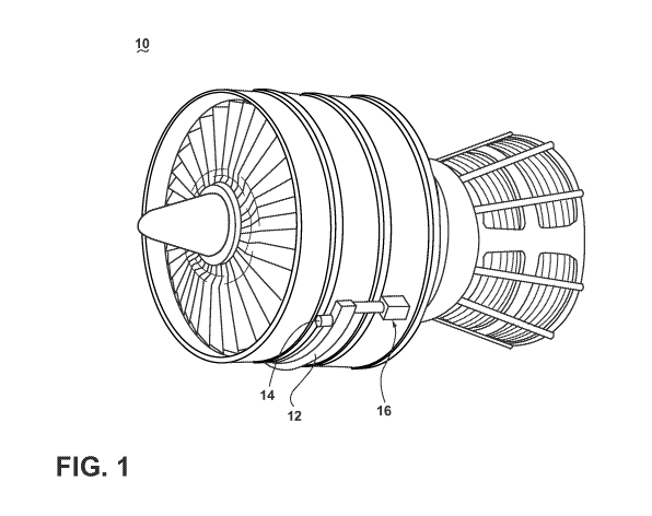
Representative Drawing
A single figure which represents the drawing illustrating the invention.
Administrative Status

For a clearer understanding of the status of the application/patent presented on this page, the site Disclaimer , as well as the definitions for Patent , Administrative Status , Maintenance Fee  and Payment History  should be consulted.

Administrative Status

Title Date
Forecasted Issue Date Unavailable
(86) PCT Filing Date 2015-04-10
(87) PCT Publication Date 2016-10-13
(85) National Entry 2017-09-28
Examination Requested 2017-09-28
Dead Application 2019-04-10

Abandonment History

Abandonment Date Reason Reinstatement Date
2018-04-10 FAILURE TO PAY APPLICATION MAINTENANCE FEE

Payment History

Fee Type Anniversary Year Due Date Amount Paid Paid Date
Request for Examination $800.00 2017-09-28
Application Fee $400.00 2017-09-28
Maintenance Fee - Application - New Act 2 2017-04-10 $100.00 2017-09-28
Owners on Record

Note: Records showing the ownership history in alphabetical order.

Current Owners on Record
GE AVIATION SYSTEMS LLC
Past Owners on Record
None
Past Owners that do not appear in the "Owners on Record" listing will appear in other documentation within the application.
Documents

To view selected files, please enter reCAPTCHA code :


To view images, click a link in the Document Description column. To download the documents, select one or more checkboxes in the first column and then click the "Download Selected in PDF format (Zip Archive)" or the "Download Selected as Single PDF" button.

List of published and non-published patent-specific documents on the CPD .

If you have any difficulty accessing content, you can call the Client Service Centre at 1-866-997-1936 or send them an e-mail at CIPO Client Service Centre.


Document
Description 
Date
(yyyy-mm-dd) 
Number of pages   Size of Image (KB) 
Abstract 2017-09-28 1 73
Claims 2017-09-28 3 99
Drawings 2017-09-28 5 281
Description 2017-09-28 2 86
Representative Drawing 2017-09-28 1 36
Patent Cooperation Treaty (PCT) 2017-09-28 1 42
International Search Report 2017-09-28 2 51
National Entry Request 2017-09-28 5 159
Cover Page 2017-12-22 1 63