Note: Descriptions are shown in the official language in which they were submitted.
CA 02981604 2017-10-02
WO 2016/164024
PCT/US2015/025083
VEHICLE DOOR SYSTEM WITH INFINITE DOOR CHECK
BACKGROUND
[0001] This
disclosure relates to a door check for a vehicle door, and more
particularly, for a vehicle passenger door.
[0002] Passenger
doors are conventionally held opened and closed using a door
check. A passenger pushes a button or engages a handle, which unlatches the
door enabling it
to swing open. The door check is interconnected between the frame and door and
includes
detents that define discrete door open positions, which hold the door open.
When the door is
opened or closed the holding force of the detent is overcome.
[0003] A
conventional door check only provides a few discrete door hold open
positions that may not coincide with the most convenient door open angle for
the passenger
to ingress or egress the vehicle. Passive infinite door checks solutions such
as US 5,410,777
have been proposed to address this shortcoming. However even such a device can
provide an
inconsistent feel when the holding force of the detent is "released" depending
on the attitude
of the vehicle. For example, if the vehicle is parked on an incline, when
released from a hold
position, the door may feel as if it may suddenly close due to the weight of
the door. A
further shortcoming of the prior art is that door checks cannot be used to
prevent the door
hitting an obstacle when the door is swung open in a tight parking situation,
which is
desirable to prevent costly repair to the door.
SUMMARY
[0004] In one
exemplary embodiment, an automotive door system includes a
hinge that is configured to support a door. A door check module is configured
to be
interconnected to one of the vehicle and the door by a linkage assembly. The
door check
module includes a housing. An output shaft is connected to the linkage
assembly and
configured to be rotatable relative to the housing. The output shaft is
configured to provide
an output torque to check the door in a desired door position. A sensor is
configured to detect
rotation of the shaft and produce a signal in response to the detected
rotation. A brake
assembly includes a shaft member that is operatively connected to the output
shaft. The
1
CA 02981604 2017-10-02
WO 2016/164024
PCT/US2015/025083
brake assembly has a normally closed position in which the shaft member is
grounded to the
housing in a door check mode. The brake assembly includes an open position
that
corresponds to one of a door closing mode and a door opening mode. The brake
assembly is
configured to move from the normally closed position to the open position in
response to the
signal.
[0005] In a further
embodiment of the above, a controller is in communication
with the sensor and the brake assembly. The controller is configured to
command the brake
assembly to move from the normally closed position and release the shaft in
response to the
signal. The signal is indicative of slippage of the shaft member in the
noimally closed
position. The controller is configured to command the brake assembly to the
nomially closed
position in response to the signal falling below a threshold value and provide
a holding torque
in the desired door position.
[0006] In a further
embodiment of any of the above, an obstacle sensor is in
communication with the controller. The obstacle sensor is configured to detect
an obstacle,
and the controller commands the door to stop with the brake assembly in the
normally closed
position in response to the detected obstacle.
[0007] In a further
embodiment of any of the above, a gearbox interconnects the
output shaft and the shaft member. The gearbox multiplies the holding torque.
[0008] In a further
embodiment of any of the above, the brake assembly is
arranged between the gearbox and the sensor.
[0009] In a further
embodiment of any of the above, the linkage assembly is
configured to be interconnected to a door pillar and to transmit the output
torque to the door
pillar.
[0010] In a further
embodiment of any of the above, the position sensor is
integrated with the brake assembly. The position sensor is configured to
detect rotation of the
shaft member, which is indicative of rotation of the output shaft.
[0011] In a further
embodiment of any of the above, the brake assembly includes
a permanent magnet grounding the shaft member to the housing in the normally
closed
position. A coil is configured to overcome a magnetic flux of the permanent
magnet to
provide an open position that permits the shaft member to freely rotate
relative to the
housing.
CA 02981604 2017-10-02
WO 2016/164024
PCT/US2015/025083
[0012] In a further
embodiment of any of the above, the coil is modulated to
provide a desired release of the brake assembly corresponding to a desired
door feel.
[0013] In a further
embodiment of any of the above, the brake assembly includes
a holding torque in the normally closed position, and the coil is configured
to be modulated to
decay the holding torque in relation to a pulse width modulation average
voltage supplied to
the coil.
[0014] In a further
embodiment of any of the above, the controller is configured to
reverse a polarity of current to the coil to supplement the magnetic flux in
the normally
closed position and is configured to increase the door arresting torque.
[0015] In a further
embodiment of any of the above, an attitude sensor is in
communication with the controller. The attitude sensor is configured to
provide an attitude of
the vehicle. 'Me controller is configured to regulate the brake assembly in
response to a signal
from the attitude sensor.
[0016] In another
exemplary embodiment, an infinite door check includes a
housing. An output shaft is configured to be rotatable relative to the
housing. The output
shaft is configured to provide an output torque to check a door in a desired
door position. A
sensor is configured to detect rotation of the shaft and produce a signal in
response to the
detected rotation. A brake assembly includes a shaft member operatively
connected to the
output shaft. The brake assembly has a normally closed position in which the
shaft member
is grounded to the housing in a door check mode. The brake assembly includes
an open
position that corresponds to one of a door closing mode and a door opening
mode. The brake
assembly is configured to move from the normally closed position to the open
position in
response to the signal. The signal is indicative of slippage of the shaft
member in the
normally closed position.
[0017] In a further
embodiment of any of the above, a gearbox interconnects the
output shaft and the shaft member. The gearbox multiplies the holding torque.
[0018] In a further
embodiment of any of the above, a linkage assembly
interconnects to the output shaft. The linkage assembly is configured to
transmit the output
torque from the output shaft to a door pillar.
3
CA 02981604 2017-10-02
WO 2016/164024
PCT/US2015/025083
[0019] In a further
embodiment of any of the above, the position sensor is
integrated with the brake assembly. The position sensor is configured to
detect rotation of the
shaft member, which is indicative of rotation of the output shaft.
[0020] In a further
embodiment of any of the above, the brake assembly includes
a peimanent magnet that grounds the shaft member to the housing in the
normally closed
position. A coil is configured to overcome a magnetic flux of the permanent
magnet to
provide an open position that permits the shaft member to freely rotate
relative to the
housing.
[0021] In a further
embodiment of any of the above, a reverse polarity of current
to the coil supplements the magnetic flux in the normally closed position and
is configured to
increase the door arresting torque.
[0022] In another
exemplary embodiment, a method of checking a door includes
the steps of holding a door in an open position with an electric brake
assembly and manually
pivoting the door in a direction about a hinge to provide a manual input. The
manual input is
detected and the electric brake assembly is released in response to the manual
input.
[0023] In a further
embodiment of any of the above, the detecting step includes
back-driving a gearbox via an output shaft and detecting rotation of the
output shaft.
[0024] In a further
embodiment of any of the above, the detecting step includes
indirectly sensing rotation of the output shaft by sensing rotation of an
electric brake
assembly shaft member.
[0025] In a further
embodiment of any of the above, the manual input includes
pushing or pulling on the door and exceeding a slip torque of a brake assembly
that holds the
door. The releasing step is performed in response to the slip torque.
[0026] In a further
embodiment of any of the above, the method includes the step
of detecting a door obstacle. The door holding step is performed in response
to the detected
obstacle.
[0027] In a further
embodiment of any of the above, the door holding step
includes reversing a polarity of current to a coil in the electric brake
assembly to supplement
the magnetic flux in a normally closed brake position and is configured to
increase the door
arresting torque.
4
CA 02981604 2017-10-02
WO 2016/164024
PCT/US2015/025083
BRIEF DESCRIPTION OF THE DRAWINGS
[0028] The disclosure can be further understood by reference to the
following
detailed description when considered in connection with the accompanying
drawings
wherein:
[0029] Figure lA is a perspective view of a vehicle door with an
infinite door
check mounted to a door pillar.
[0030] Figure 1B is an enlarged perspective view of the door
illustrating a linkage
assembly of the infinite door check.
[0031] Figure 2 is a schematic view of an example door system embodiment
that
uses the infinite door check.
[0032] Figure 3A is a perspective view of the infinite door check.
[0033] Figure 3B is a cross-sectional view of the infinite door check
taken along
line 3B-3B of Figure 3A.
[0034] Figure 4 is a cross-sectional view of a brake assembly for the
infinite door
check.
[0035] Figure 5 is a flow chart depicting the operation of the infinite
door check.
[0036] Figure 6 is another flow chart depicting the operation of the
infinite door
check.
[0037] Figure 7A is a graph illustrating brake assembly voltage versus
time.
[0038] Figure 7B is a graph illustrating brake assembly holding torque
versus
time according to the voltage-time relationship shown in Figure 7A.
[0039] The embodiments, examples and alternatives of the preceding
paragraphs,
the claims, or the following description and drawings, including any of their
various aspects
or respective individual features, may be taken independently or in any
combination. Features
described in connection with one embodiment are applicable to all embodiments,
unless such
features are incompatible.
DETAILED DESCRIPTION
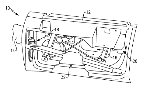
[0040] A conventional automotive vehicle 10 (only a portion shown)
typically
includes multiple doors 12 (one shown) used for egress and ingress to the
vehicle passenger
compartment and/or cargo area. In the example, the door 12 is a passenger
door. The door 12 is
pivotally mounted by hinges 15 to a door pillar 14, such as an A-pillar or B-
pillar, about which the
door is movable between opened and closed positions. The door 12 has a cavity
16 that typically
includes an impact intrusion beam, window regulator, and other devices. A door
check module 18
is arranged within the cavity 16, although the door check module 18 can
instead be arranged in the
door pillar 14, if desired. Mounting the door check module 18 near the hinges
15 minimizes the
impact on door inertia.
100411 The door check module 18 is part of a door system 20 (Figure
2) that holds
the door 12 in an open position without the discrete detents typically found
in conventional door
checks. Instead the system 20 is capable of holding the door in an infinite
number of open
positions. Moreover, the system 20 can provide a consistent feel during
release of the door
regardless of vehicle attitude and be used to actively stop the door when an
obstacle is detected in
the swing path of the door using an obstacle detection sensor.
100421 Referring to Figure 1B, the door check module 18 is connected
to the door
pillar 14 by a linkage assembly 21. The linkage assembly 21 transmits the
opening and closing
forces to the door check module 18 and also stops and holds or only holds the
door 12 open when
desired.
100431 Referring to Figure 2, the system 20 includes a controller 22,
or electronic
control unit (ECU), that receives inputs from various components as well as
sends command
signals to the door check module 18 to selectively hold the door 12 open. A
direct current (DC)
power supply 24 is connected to the controller 22, which selectively provides
electrical power to
the door check module 18 in the form of commands. A latch 26, which is carried
by the door 12
(Figure 1A), is selectively coupled and decoupled to a striker 28 mounted to
the door pillar 14. The
latch 26 may be a power pull-in latch in communication with the controller 22,
but a conventional
mechanical latch may also be used. In one embodiment, the latch 26 includes a
sensor that can
communicate its open or closed state to the controller 22.
100441 A vehicle attitude sensor 29 is in communication with the
controller 22 and is
used to detect the attitude of the vehicle, which is useful in controlling the
motion of the door 12
when released by the door check module 18.
100451 In one example, an obstruction sensor 32, such as an
ultrasonic sensor, is in
communication with the controller 22 and is used to generate a stop command if
an
6
CA 2981604 2018-12-18
CA 02981604 2017-10-02
WO 2016/164024
PCT/US2015/025083
obstruction is detected while the passenger is opening the door. The
obstruction sensor 32 is
mounted on the outer sheet metal of the door 12, for example. It should be
understood that
other sensors, such as optical sensors, can also be used and that other sensor
locations, such
as in the vehicle's door mirror base, can also be used to sense an
obstruction.
[0046] Referring to
Figures 2 and 3B, the door check module 18 includes a
housing 33, which may be provided by one or more discrete structures secured
to one
another. A brake assembly 38 is grounded to the door 12 via the housing 33 and
is selectively
connected to a shaft member 39. One suitable brake assembly is available from
Sinfonia NC,
Model No. ERS-260L/FMF. This brake assembly 38 provides a relatively small
amount of
holding torque, for example, 8 Nm.
[0047] A gearbox 36
is used to multiply the holding torque provided by the brake
assembly 38. In the example one gearbox is used, although more gearboxes may
be used. The
gearbox 36 is arranged within the housing 33 and is coupled to the brake
assembly 38 by the
shaft member 39. In one example, the gearbox 36 is a spur gear set providing a
6.25:1
reduction. Of course, it should be understood that other gear configurations
and gear
reductions may be provided. The total holding torque provided by the door
check module 18
in the example embodiment is 50 Nm. Any torque applied to the brake assembly
38 above
this threshold holding torque will cause the brake to slip, permitting the
shaft member 39 to
rotate.
[0048] The brake
assembly 38 has a normally closed position in which the shaft
member 39 is grounded to the housing 33 and prevented from rotating. The brake
assembly
38 also includes an opened position corresponding to one of a door closing
mode and a door
opening mode. In the open position, the brake assembly 38 permits the shaft
member 39 to
rotate freely. Otherwise, the brake assembly 38 holds or "checks" the door 12
in its current
position.
[0049] A position
sensor 40, which is in communication with the controller 22,
monitors the rotation of a component of the door check module 18, for example,
the shaft
member 39. In one example, the position sensor 40 is an integrated Hall effect
sensor that
detects the rotation of the shaft member 39.
[0050] Referring to
Figure 3A, an output shaft 41 of the gearbox 36 is coupled to
the linkage assembly 21. A lever 42 is mounted to the output shaft 41 at one
end and to a
7
CA 02981604 2017-10-02
WO 2016/164024
PCT/US2015/025083
strap 44 at the other end. The strap 44 is pinned to a bracket 46 fastened to
the door pillar 14.
The linkage assembly 21 is designed to provide a holding torque of
approximately the same
as the desired door holding moment.
[0051] One example
brake assembly 38 is shown in more detail in Figure 4. The
shaft member 39 is carried by a bearing 50 mounted to the housing 33. One end
52
communicates with the position sensor 40, and the other end 54 is connected to
the gearbox
36. A drive ring 56 is secured to the end 54 and supports a pet __ manent
magnet 58. A spring
60, which may be a leaf spring in one example, is arranged between the drive
ring 56 and
permanent magnet 58 to bias the permanent magnet 58 away from the housing 33.
A
magnetic field generated by the permanent magnet 58 pulls the drive ring 56
with a much
greater force than the spring 60 toward the housing 33. Friction material 62
is supported by
the housing 33 and engages the permanent magnet 58 in the normally closed
position to
provide the torque at which the permanent magnet 58 will slip with respect to
the housing 33,
again, about 8 Nm.
[0052] A magnetic
flux circuit, or coil 64, is arranged within the housing 33 and
communicates with the controller 22 via wires 66. When energized with a
defined polarity
current, the coil 64 creates a counteracting magnetic flux to the permanent
magnet 58 that is
sufficient to overcome the magnetic field of the permanent magnet 58, thus
allowing the
spring 60 to move the permanent magnet 58 out of engagement with the friction
material 62
to the position shown in Figure 4. In this opened position, the shaft member
39 is permitted to
rotate freely relative to the housing 33. The brake assembly components can be
reconfigured
in a manner different than described above and still provide desired selective
brake hold
torque.
[0053] The magnetic
flux circuit, or coil 64 can also he powered in reverse
polarity to add to the magnetic flux of the permanent magnet 58. This is
advantageous when a
stop command is generated by the controller 22 due to the detection of an
obstruction. It has
been shown that the addition coil generated magnetic flux increase the maximum
holding
torque by -50%, for example. Therefore, the brake arresting torque increases
to 12 Nm in
such an example, which in turn provides a maximum arresting torque of 75 Nm.
[0054] One example
operating mode 70 is shown in Figure 5. With the brake
assembly 38 in the noimally closed position, a holding torque is generated to
maintain the
8
door 12 in its current position. In the absence of slippage in the brake
assembly 38, the door
velocity is detected as zero via the position sensor 40.
100551 The door 12 is pushed or pulled further open or closed by the
user, which
causes the linkage assembly 21 to rotate the output shaft 41 and back-drive
the gearbox 36 and
shaft member 39. When enough torque has been applied to slip the brake torque
of the normally
closed brake assembly 38 (in the example, 50 Nm), the shaft member 39 will
rotate. An angular
movement of the shaft member 39 is thus detected by the position sensor 40,
which is indicative
of rotation of the output shaft 41.
100561 A detected threshold angular movement, for example, 2 ,
provides an input
that is interpreted as a desired door motion command by the controller 22. Of
course, other angular
thresholds can be used, if desired. The position sensor 40 is used to detect
the angular position of
the door 12 as well as door velocity, which may be useful in controlling the
brake assembly 38
based upon vehicle attitude.
100571 Thus, in response to the input from the position sensor 40,
the controller 22
will command the brake assembly 38 to release the shaft member 39, which will
then rotate freely
relative to the housing 33, permitting the door 12 to move. Once the shaft
member 39 angular
movement and/or velocity has been detected by the position sensor 40 to be
about 0 (indicative of
arrested door motion), the coil 64 is de-energized to reengage the brake
assembly 38 and hold the
door 12 in its current position.
100581 Door motion is arrested at the fully open and fully closed
positions.
Additionally, the user can physically hold the door 12 in a desired position,
preventing further
movement of the door 12, which will be detected by the position sensor 40. The
controller 22 then
de-energizes the brake assembly 38, which will hold the door 12 where the user
stopped the door
12, providing an "infinite" door check. That is, the door 12 can be held by
the door check module
18 in any position rather than only in discrete detent positions. This feature
is particular useful in
tight parking situations where a door cannot be fully opened. The door can
then be positioned in
close proximity to an obstacle adjacent to the door and held by the user, at
which point the brake
assembly 38 will hold the door position, thus providing a maximum opening for
the user to enter
and exit the vehicle.
100591 In a further example operating mode 80 is shown in Figure 6
whereby a stop
command is generated by the controller 22 due to an obstacle signal from
obstacle
9
CA 2981604 2018-12-18
sensor 32. This stop command includes a reverse polarity current to the brake
that increases the
brake holding torque to 12 Nm, which in turn results in a door arresting
torque of 75 Nm by
multiplication of the gearbox 36. The arresting torque ensures a rapid
arresting of the door to
prevent contact with the obstacle. When the door velocity is detected as zero
via the position sensor
40 the reverse polarity current is dropped and the holding torque of the door
check module 18
reverts to 50 Nm. The holding torque decay of the brake assembly 38 can be
adjusted with pulse-
width modulation of the coil 64. For example the nominal brake holding torque
can be reduced to
6.4 Nm by applying approximately 4 V to the coil through pulse width
modulation and thus provide
a door check hold torque of approximately 40 Nm on level ground. In a further
example, the vehicle
attitude is detected with the attitude sensor 29 to vary the holding torque
provided by the brake
assembly 38 to provide a consistent holding torque regardless of vehicle
incline or decline, which
creates predictable door motion for the user. For example, a greater holding
torque would be
applied by the brake assembly 38 when the vehicle is on an incline than when
the vehicle is on
level ground.
[00601 In a
second example it may be desirable to "soft" release the brake assembly
38 to prevent an abrupt door movement that may cause an undesirable door feel
for the customer.
For example, 50 Nm of holding torque may produce a force in the linkage
assembly 21 at the door
pillar 14 of 700-900 N, which is capable of producing an audible sheet metal
popping sound due
to the sudden release of the stored hold moment energy. To address this
potential undesired
scenario, a soft release function is used, as shown in Figure 7A, to ramp the
pulse-width modulation
signal from the controller 22 over, for example, 0.2 seconds, to full
strength. As a result, the
electrical counter field to the permanent magnetic field is slowly increased,
thus reducing the brake
hold torque from full strength to released, as shown in Figure 7B, over the
0.2 seconds, which
provides a "soft" release of the brake action. In the example, a gradual,
linear increase in voltage
provides a smooth, non-linear decay of holding torque. However, it should be
understood that other
voltage-torque-time relationships may be provided electrically and/or
mechanically to provide a
desired door feel.
100611 It should
also be understood that although a particular component arrangement
is disclosed in the illustrated embodiment, other arrangements will benefit
herefrom. Although
particular step sequences are shown, and described, it
should
CA 2981604 2018-12-18
CA 02981604 2017-10-02
WO 2016/164024
PCT/US2015/025083
understood that steps may be perfomied in any order, separated or combined
unless otherwise
indicated and will still benefit from the present invention.
[0062] Although the
different examples have specific components shown in the
illustrations, embodiments of this invention are not limited to those
particular combinations.
It is possible to use some of the components or features from one of the
examples in
combination with features or components from another one of the examples.
[0063] Although an
example embodiment has been disclosed, a worker of
ordinary skill in this art would recognize that certain modifications would
come within the
scope of the claims. For that reason, the following claims should be studied
to determine
their true scope and content.
11