Note: Descriptions are shown in the official language in which they were submitted.
ENCLOSURE COVER ASSEMBLIES
CROSS REFERENCE TO RELATED APPLICATIONS
[0001] The present application is based on and claims benefit from co-pending
U.S.
Provisional Application Serial No. 62/404,788, filed October 6, 2016 entitled
"Enclosure Cover
Assemblies".
BACKGROUND
Field
[0002] The present disclosure relates generally to enclosure cover assemblies
and, more
particularly, to cover assemblies having frames and covers for precast utility
enclosures that can
support the weight of vehicles enabling the enclosure to be used in high
vehicle traffic
environments.
Description of the Related Art
100031 Utility companies, such as water, electric, gas, and/or cable
television utilities often use
subterranean conduits and enclosures to deliver their product to customers.
For example,
electrical utilities run electrical wires through underground conduits and
provide workman
access to such wires using buried utility enclosures that have covers at or
slightly above grade.
The utility enclosures can be buried in the ground, or under roads or
sidewalks. The tops of
enclosures buried in roadways are subject to significant vehicle weights. To
protect buried
1
CA 2981780 2017-10-06
utility enclosures from damage caused by vehicle traffic, the covers need to
be able to withstand
such weight.
SUMMARY
100041 The present disclosure provides embodiments of cover assemblies for use
with direct
burial enclosures. In one exemplary embodiment, an enclosure cover assembly
comprises a
frame that can be secured to an enclosure and a cover that can be separately
secured to the frame.
The frame has a central opening providing access to an interior of the
enclosure, an overhang and
a cover receiving ledge. The cover receiving ledge may be offset from a top of
the overhang.
The cover receiving ledge includes at least one enclosure mounting tab
positioned to align with
at least one mounting structure of an enclosure and at least one cover
mounting tab. The cover is
dimensioned to rest on the cover receiving ledge of the frame, and has at
least one opening
aligned with the at least one cover mounting tab so that the cover can be
secured to the frame.
100051 In one exemplary embodiment, an enclosure cover assembly comprises a
frame and a
cover. The frame has a pair of side walls, a pair of end walls and a central
opening, wherein an
end of each side wall meets an end of an end wall. The side walls and end wall
include an
overhang and a cover receiving ledge. The frame may include at least one
stabilizing bracket
extending from the overhang such that when the frame is installed on an
enclosure the at least
one stabilizing bracket can be embedded in concrete surrounding the frame. The
cover receiving
ledge may be offset from a top of the overhang. The cover receiving ledge
includes at least one
enclosure mounting tab positioned to align with at least one mounting
structure of an enclosure
and at least one cover mounting tab. The cover is dimensioned to rest on the
cover receiving
ledge and has at least one opening aligned with the at least one cover
mounting tab such that the
cover can be secured to the frame.
2
CA 2981780 2017-10-06
[0005A] In a broad aspect, the present invention pertains to an underground
utility enclosure
cover assembly comprising a frame having a central opening, the frame having a
unitary structure
including an overhang, a cover receiving ledge offset from a top of the
overhang, and at least one
stabilizing member extending from the overhang such that when the frame is
installed on an
enclosure, the at least one stabilizing member can be embedded in concrete
surrounding the frame.
The cover receiving ledge has at least one enclosure mounting tab positioned
to align with at least
one mounting structure of an enclosure. There is at least one cover mounting
tab, and a cover
dimensioned to rest on the cover receiving ledge, and at least one opening
aligned with the at least
one cover mounting such that the cover can be secured to the frame, the frame
and the cover being
made of one of steel, galvanized steel, cast iron, ductile iron or aluminum
and are capable of
supporting vertical loads of at least 40,000 lbs.
[0005B] In a further aspect, the present invention provides an underground
utility enclosure
cover assembly comprising a unitary structured frame including a pair of walls
and a pair of end
walls. An end of each side wall meets an end of an end wall forming a central
opening, the side
walls and end wall having an overhang and a cover receiving ledge offset from
a top of the
overhang. At least one stabilizing member extends from the overhang such that
when the frame is
installed on an enclosure, the at least one stabilizing member can be embedded
in concrete
surrounding the frame. The cover receiving ledge has at least one enclosure
mounting tab
positioned to align with at least one mounting structure of an enclosure, and
at least one cover
mounting tab. A cover is dimensioned to rest on the cover receiving ledge and
at least one opening
is aligned with the at least one cover mounting tab such that the cover can be
secured to the frame.
The frame and the cover are made of one of steel, galvanized steel, cast iron,
ductile iron or
aluminum, and are capable of supporting vertical loads of at least 40,000 lbs.
2a
CA 2981780 2021-07-16
[0005C] In a still further aspect, there is provided an underground utility
enclosure assembly
comprising an enclosure, and an enclosure cover assembly. There is a frame
having a central
opening, the frame having a unitary structure including an overhang, a cover
receiving ledge offset
from a top of the overhang, and at least one stabilizing member extending from
the overhang such
that when the frame is installed on an enclosure, the at least one stabilizing
member can be
embedded in concrete surrounding the frame. The cover receiving ledge has at
least one enclosure
mounting tab positioned to align with at least one mounting structure of the
enclosure, and at least
one cover mounting tab. A cover is dimensioned to rest on the cover receiving
ledge and at least
one opening is aligned with the at least one cover mounting tab such that the
cover can be secured
to the frame, the frame and the cover being made of one of steel, galvanized
steel, cast iron, ductile
iron or aluminum and are capable of supporting vertical loads of at least
40,000 lbs.
[0005D] In a yet further aspect, the present invention provides an underground
utility enclosure
assembly comprising an enclosure and an enclosure cover assembly. There is a
unitary structured
frame including a pair of side walls, and a pair of end walls wherein an end
of each side wall meets
an end of an end wall forming a central opening. The side walls and end wall
have an overhang
and a cover receiving ledge offset from a top of the overhang, and at least
one stabilizing member
extending from the overhang such that when the frame is installed on an
enclosure, the at least one
stabilizing member can be embedded in concrete surrounding the frame. The
cover receiving ledge
has at least one enclosure mounting tab positioned to align with at least one
mounting structure of
the enclosure, and at least one cover mounting tab. A cover is dimensioned to
rest on the cover
receiving ledge and at least one opening is aligned with the at least one
cover mounting tab such
that the cover can be secured to the frame. The frame and the cover are made
of one of steel,
galvanized steel, cast iron, ductile iron or aluminum and are capable of
supporting vertical loads of
at least 40,000 lbs.
2b
CA 2981780 2021-07-16
BRIEF DESCRIPTION OF THE DRAWINGS
[0006] A more complete appreciation of the present disclosure and many of the
attendant
advantages thereof will be readily obtained as the same becomes better
understood by reference
to the following detailed description when considered in connection with the
accompanying
drawings, wherein:
[0007] Fig. 1 is top perspective view of an exemplary embodiment of a frame
and cover of a
cover assembly according to the present disclosure used to cover direct burial
enclosures;
[0008] Fig. 2 is a side elevation view of the frame of Fig. 1;
[0009] Fig. 3 is top plan view of the frame of Fig. 1;
[0010] Fig. 4 is top plan view of another exemplary embodiment of the frame
according to the
present disclosure illustrating a segmented cover receiving ledge;
[0011] Fig. 5 is a bottom plan view of the frame of Fig. 3;
[0012] Fig. 6 is a cross-sectional view of the frame of Fig. 3 taken along
line 6-6;
[0013] Fig. 7 is a cross-sectional view of the frame of Fig. 3 taken along
line 7-7;
[0014] Fig. 8 is a partial cross-sectional view of the frame of Fig. 3 taken
along line 8-8;
[0015] Fig. 9 is atop plan view of the cover assembly according to the present
disclosure
secured to an underground enclosure surrounded by concrete;
[0016] Fig. 10 is a top plan view of the cover of Fig. 1;
[0017] Fig. 11 is a cross sectional view of the cover of Fig. 10 taken along
line 11-11;
3
CA 2981780 2017-10-06
[0018] Fig. 12 is a top perspective view of another exemplary embodiment of a
frame and
cover of a cover assembly according to the present disclosure used to cover
direct burial
enclosures;
[0019] Fig. 13 is a side elevation view of the cover of Fig. 12; and
[0020] Fig. 14 is an end elevation view of the cover of Fig. 12.
DETAILED DESCRIPTION
[0021] The present disclosure provides embodiments of cover assemblies for use
with direct
burial enclosures. The exemplary embodiments of the cover assemblies according
to the present
disclosure include a frame that is releasably secured to a top portion of a
direct burial enclosure
and cover that is releasably secured to the frame.
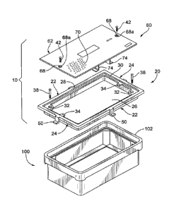
[0022] Referring now to the figures, an enclosure cover assembly according to
an exemplary
embodiment of the present disclosure is shown in Figs. 1 and 2, and referred
to herein as the
"assembly." The assembly 10 includes a frame 20 and a cover 60 that are used
to cover direct
burial enclosures 100 that may be located in an area with high vehicle
traffic. The direct burial
enclosures 100 are made of high strength concrete, such as polymer concrete,
fiberglass
reinforced polymer concrete, plastic composites or other high strength
material. The frame 20
and cover 60 may be rectangular in shape, square in shape, circular in shape
or any other shape,
and are dimensioned to fit on a direct burial enclosure 100, such as the
enclosure 100 shown in
Fig. 1, and to be relcasably secured to the enclosure 100. The frame 20 and
cover 60 are made of
a rigid material sufficient to support vertical loads created by pedestrian
and/or vehicle traffic.
The frame 20 and cover 60 are preferably made of a rigid material capable of
supporting vertical
loads that meet the American Association of State Highway Transportation
Officials (AASHTO)
4
CA 2981780 2017-10-06
H-20 and HS-20 loading standards, such as vertical loads of at least about
40,000 lbs. Examples
of suitable materials include steel, galvanized steel, cast iron, ductile iron
and aluminum.
[0023] Referring to Figs. 2-8, in the exemplary embodiment shown, the frame 20
has two side
walls 22 and two end walls 24 forming a rectangular shaped frame. The side
walls 22 and end
walls 24 may be made as a unitary structure or they may be secured together
by, for example,
welds. The side walls 22 and end walls 24 when joined form a central opening
26 as shown in
Fig. 1, permitting access to an interior of the enclosure 100. The side walls
22 and end walls 24
may be collectively referred to herein as the -walls." An upper portion of the
walls has an
overhang 28 and a cover receiving ledge 30. The overhang 28 is configured to
rest on a top edge
102, as shown in Fig. 1, of the enclosure 100. The cover receiving ledge 30 is
preferably offset
from the top of the overhang 28 so that when the cover 60 is positioned or
nested within the
frame 20, a top surface of the cover is even with the top of the overhang. The
cover receiving
ledge 30 preferably extends along the entire inner periphery of the upper
portion of the walls 22
and 24, as shown. However, one skilled in the art would readily appreciate
that the cover
receiving ledge 30 may comprise a segmented structure, such as the segmented
structure shown
in Fig. 4.
100241 The cover receiving ledge 30 includes one or more enclosure mounting
tabs 32 and one
or more cover mounting tabs 34, as shown in Figs. 3 and 5. The enclosure
mounting tabs 32 and
cover mounting tabs 34 can be integrally formed into the cover receiving ledge
30 and thus the
side walls 22 and end walls 24, are secured to the cover receiving ledge 30
using known
techniques, such as welding.
[0025] The enclosure mounting tabs 32 can be positioned anywhere along the
side walls 22,
the end walls 24 or both the side walls and the end walls. Preferably, the
enclosure mounting
tabs 32 are positioned at the comers of the walls 22 and 24 so that the frame
20 can be secured to
existing mounting structures. Non-limiting examples of such mounting
structures include
threaded apertures or clips, in for example the corners of the underground
enclosure 100. In the
CA 2981780 2017-10-06
embodiment shown, there are two enclosure mounting tabs 32 positioned at
opposite corners of
the walls 22 and 24. Each enclosure mounting tab 32 includes an aperture 36
through which a
mounting fastener 38, e.g., the bolt 38 as seen in Fig. 1, can pass. As a non-
limiting example, the
threaded aperture 36 and mounting fastener 38 may be similar to a wedge ramp
style bolt and nut
configuration that resists backing out of the bolt caused by vibrations on a
road surface or
pedestrian walkway due to vehicle or pedestrian traffic. The aperture 36 may
include a recess
portion 36a, shown in Fig. 8, so that the head of the mounting bolt 38 and a
washer (not shown)
may come to rest. By recessing the bolt 38 head, the cover 60 is flush with
the cover receiving
ledge 30 when installed.
[0026] The one or more cover mounting tabs 34 can be positioned anywhere along
the side
walls 22, the end walls 24 or both the side walls and the end walls so that
the cover 60 can be
secured to the frame. In the embodiment shown, there are two cover mounting
tabs 34, each
positioned at or near a midpoint along the end walls 24 of the frame 20. As a
non-limiting
example, each cover mounting tab 34 may include a threaded aperture 40 through
which a
mounting fastener 42, seen in Fig. 1, can be used to secure the cover 60 to
the frame 20.
[0027] Extending from an outer surface of the overhang 28 on the side walls
22, the end walls
24 or both the side walls and the end walls are one or more stabilizing
brackets 50. As a non-
limiting example, in the embodiment shown, each side wall 22 has one
stabilizing bracket 50 and
each end wall 24 has one stabilizing bracket. However, each side wall can have
more than
stabilizing bracket, and each end wall can have more than one stabilizing
bracket. Each
stabilizing bracket 50 extends downward and away from the walls 22 and /or 24
so that a portion
of the stabilizing brackets can occupy an area around a perimeter of the
frame. The stabilizing
brackets 50 can then be embedded in concrete poured around the enclosure 100,
as shown in Fig.
9. The stabilizing brackets 50 when embedded in concrete distribute vertical
loads on the
assembly 10 to the surrounding concrete thus stabilizing the frame 20 and
cover 60 relative to the
surrounding concrete. In the embodiment shown, the stabilizing brackets 50 are
L-shaped
6
CA 2981780 2017-10-06
brackets, as seen in Figs. 6 and 7. However the stabilizing brackets 50 may
come in many
different shapes and sizes.
[0028] Referring now to Figs. 10 and 11, an exemplary embodiment of a cover 60
is shown.
In this exemplary embodiment, the cover 60 comprises a body 62 having a top
surface 62a and a
bottom surface 62b, two side edges 64 and two end edges 66 forming a
rectangular shaped cover.
As noted, the cover 60 is configured and dimensioned to rest on the cover
receiving ledge 30 of
the frame 20. As also noted, the body 62 is made of a rigid material capable
of supporting loads
of at least about 40,000 lbs. The body 62 also includes one or more apertures
68 through which
mounting fasteners 42, e.g., the bolts seen in Fig. 1, can pass. As a non-
limiting example, the
threaded aperture 68 and mounting fasteners 42 may be similar to a wedge ramp
style bolt and
nut configuration that resists backing out of the bolt caused by vibrations on
a road surface or
pedestrian walkway due to vehicle or pedestrian traffic. Preferably, the
number of apertures 68
corresponds to the number of cover mounting tabs 34 so that the mounting
fasteners 42 can be
passed through the body 62 and threaded into the threaded apertures 40 in
corresponding cover
mounting tabs 34. The apertures 68 may include a recess portion 68a, shown in
Fig. 11, so that
the mounting fastener 42, e.g., the head of the mounting bolt and a washer
(not shown), may
come to rest. Recessing the mounting fastener 42 prevents the mounting
fastener from extending
above the top surface 62a of the body 62 when installed. The top surface 62a
of the body 62
may include one or more slip resistant members 70. The one or more slip
resistant members 70
may comprise, for example, treads shown in Fig. 10, slip resistant paints,
slip resistant tapes, or
other slip resistant materials or structures. The top surface 62a of the body
62 may include one
or more openings 72 where a hook or other tool may be used to lift the cover
60 away from the
frame 20 to permit access to an interior of the enclosure 100. The cover 60
may also include one
or more ribs 74 that are provided to enhance the vertical load capacity of the
cover 60. The ribs
may be positioned to extend from one side edge 64 to the other side edge 64 as
shown in Fig. 10,
one end edge 66 to the other end edge 66, or the ribs 74 may be arranged in
different patterns as
7
CA 2981780 2017-10-06
is known. A ground lug 80 may be secured to the body 62 so that the ground lug
extends from
the bottom surface 62b of the body. The ground lug 80 can be connected to a
ground wire or rod
and used to electrically ground the cover 60 and thus the frame 20 via the
mounting fasteners 42
between the cover 60 and the frame 20.
[0029] Referring now to the Figs. 12-14, another exemplary embodiment of an
enclosure cover
assembly according to the present disclosure is shown. The assembly 140
includes a frame 150
and a cover 180 that are used to cover direct burial enclosures 100, such as
the enclosure 100
shown in Fig. 1 and described above, that may be located in an area with high
vehicle traffic.
The frame 150 and cover 180 may be rectangular in shape, square in shape,
circular in shape or
any other shape, and are dimensioned to fit on a direct burial enclosure, such
as the enclosure
100 shown in Fig. 1, and to be releasably secured to the enclosure. The frame
150 and cover 180
are made of a rigid material sufficient to support vertical loads created by
pedestrian and/or
vehicle traffic. The frame 150 and cover 180 are preferably made of a rigid
material capable of
supporting vertical loads that meet the American Association of State Highway
Transportation
Officials (AASHTO) H-20 and HS-20 loading standards, such as vertical loads of
at least about
40,000 lbs. Examples of suitable materials include steel, galvanized steel,
cast iron, ductile iron
and aluminum.
100301 Continuing to refer to Fig. 12, in the exemplary embodiment shown, the
frame 150 has
two side walls 152 and two end walls 154 forming a rectangular shaped frame.
The side walls
152 and end walls 154 may be made as a unitary structure or they may be
secured together by,
for example, welds. The side walls 152 and end walls 154 when joined form a
central opening
156 permitting access to an interior of an enclosure. The side walls 152 and
end walls 154 may
be collectively referred to herein as the "walls." An upper portion of the
walls has an overhang
158 and a cover receiving ledge 160. The overhang 158 is configured to rest on
a top edge 102
of the enclosure 100, seen in Fig. 1. The cover receiving ledge 160 is
preferably offset from the
top of the overhang 158 so that when the cover 180 is positioned or nested
within the frame 150,
8
CA 2981780 2017-10-06
a top surface of the cover 180 is even with the top of the overhang. The cover
receiving ledge
160 preferably extends along the entire inner periphery of the upper portion
of the walls 152 and
154, as shown. However, one skilled in the art would readily appreciate that
the cover receiving
ledge 160 may comprise a segmented structure, such as the segmented structure
shown in Fig. 4.
[0031] In the exemplary embodiment shown in Fig. 12, the cover receiving ledge
160 includes
one or more enclosure mounting tabs 162 used for securing the frame 150 to an
enclosure. The
enclosure mounting tabs 162 can be integrally formed into the cover receiving
ledge 160 and
thus the side walls 152 and end walls 154, or the enclosure mounting tabs can
be secured to the
cover receiving ledge 160 using known techniques, such as welding. The
enclosure mounting
tabs 162 can be positioned anywhere along the side walls 152, the end walls
154 or both the side
walls and the end walls. Preferably, the enclosure mounting tabs 162 are
positioned at the
corners of the walls 152 and 154 so that the frame 150 can be secured to
existing mounting
structures. Non-limiting examples of such mounting structures include threaded
apertures or
clips, in for example the corners of the enclosure 100. In the embodiment
shown, there are two
enclosure mounting tabs 162 positioned at opposite corners of the walls 152
and 154. Each
enclosure mounting tab 162 includes an aperture 164 through which a mounting
fastener 166,
e.g., a bolt, can pass. As a non-limiting example, the threaded aperture 164
and mounting
fastener 166 may be similar to a wedge ramp style bolt and nut configuration
that resists backing
out of the bolt caused by vibrations on a road surface or pedestrian walkway
due to vehicle or
pedestrian traffic. The aperture 164 may include a recess portion 164a so that
the head of the
mounting fastener 166, e.g, the head of the bolt and a washer (not shown) may
come to rest. By
recessing the mounting fastener 166, the cover 180 can rest flush with the
cover receiving ledge
160 when installed.
[0032] The cover receiving ledge 160 also includes one or more cover mounting
inserts 170
used to secure the cover 180 to the frame 150. The one or more cover mounting
inserts 170 can
be positioned anywhere along the cover receiving ledge 160 of the side walls
152, the end walls
9
CA 2981780 2017-10-06
154 or both the side walls and the end walls so that the cover 180 can be
secured to the frame
150. In the embodiment shown, there are a plurality of cover mounting inserts
170 positioned
along the cover receiving ledge 160 of the side walls 152 and the end walls
154. As a non-
limiting example, each cover mounting insert 170 may include a threaded
aperture through
which a mounting fastener 166 can be used to secure the cover 180 to the frame
150.
100331 Extending from an outer surface of the overhang 158 on the side walls
152, the end
walls 154 or both the side walls and the end walls are one or more stabilizing
brackets 172. As a
non-limiting example, in the embodiment shown, each side wall 152 has three
stabilizing
brackets 172 and each end wall 154 has one stabilizing bracket 172. However,
each side wall
can have less than or more than three stabilizing brackets, and each end wall
can have more than
one stabilizing bracket. Each stabilizing bracket 172 extends downward and
away from the
walls 152 and/or 154 so that a portion of the stabilizing brackets can occupy
an area around a
perimeter of the frame 150. The stabilizing brackets 172 can then be embedded
in concrete
poured around the enclosure 100, as shown in Fig. 9. The stabilizing brackets
172 when
embedded in concrete distribute vertical loads on the assembly 140 to the
surrounding concrete
thus stabilizing the frame 150 and cover 180 relative to the surrounding
concrete. In the
embodiment shown, the stabilizing brackets 172 are L-shaped brackets. However,
the stabilizing
brackets 172 may come in many different shapes and sizes.
100341 Continuing to refer to Fig. 12, an exemplary embodiment of a cover 180
is shown. In
this exemplary embodiment, the cover 180 includes a body 182 having a top
surface 182a and a
bottom surface 182b, two side edges 184 and two end edges 186 forming a
rectangular shaped
cover. As noted, the cover 180 is configured and dimensioned to rest on the
cover receiving
ledge 160 of the frame 150. As also noted, the body 182 is made of a rigid
material capable of
supporting loads of at least about 40,000 lbs. The body 182 also includes one
or more apertures
188 through which mounting fasteners 166 can pass. The number of apertures 188
may
correspond to the number of cover mounting inserts 170 so that the mounting
fasteners 166 can
CA 2981780 2017-10-06
be passed through the body 182 and threaded into the threaded inserts 170 in
the cover receiving
ledge 160. In the exemplary embodiment shown, there are four apertures 188
corresponding to
the four cover mounting inserts 170 along the side walls 152 of the frame 150.
The apertures
188 may include a recess portion 188a so that the head of the mounting
fastener 166 and a
washer (not shown) may come to rest. Recessing the mounting fastener 166
prevents the
mounting fastener from extending above the top surface 182a of the body 182
when installed.
The top surface 182a of the body 182 may include one or more slip resistant
members 190. The
one or more slip resistant members 190 may comprise, for example, treads, slip
resistant paints,
slip resistant tapes, or other slip resistant materials or structures. The top
surface 182a of the
body 182 may include one or more openings 192 where a hook or other tool may
be used to lift
the cover 180 away from the frame 150 to permit access to an interior of the
enclosure 100. The
cover 180 may also include one or more ribs 194, seen in Figs. 13 and 14, that
are provided to
enhance the vertical load capacity of the cover 180. In an exemplary
embodiment, ribs 194 may
be positioned so they extend from a point spaced from one side edge 184 to a
point spaced from
the other side edge 184, as seen in Fig. 14, and ribs 194 may be positioned so
they extend from a
point spaced from one end edge 186 to a point spaced from the other end edge
186, as seen in
Fig. 13. In another exemplary embodiment, the ribs may be positioned to extend
from one side
edge 184 to the other side edge 184, one end edge 186 to the other end edge
186, or the ribs 194
may be arranged in different patterns as is known. A ground lug, similar to
ground lug 80 shown
in Fig. 11, may be secured to the body 182 so that the ground lug extends from
the bottom
surface 182b of the body. The ground lug can be connected to a ground wire or
rod and used to
electrically ground the cover 180 and thus the frame 150 via the mounting
fasteners 166 between
the cover 180 and the frame 150.
100351 While illustrative embodiments have been described and illustrated
above, it should be
understood that these are exemplary and are not to be considered as limiting.
Additions,
deletions, substitutions, and other modifications can be made without
departing from the spirit or
11
CA 2981780 2017-10-06
scope of the present disclosure. Accordingly, the invention is not to be
considered as limited by
the foregoing description.
12
CA 2981780 2017-10-06