Note: Descriptions are shown in the official language in which they were submitted.
Electric heating system, electric heating panel,
method of manufacturing thereof, laying structure
thereof, and laying method thereof
CROSS-REFERENCE TO RELATED APPLICATIONS
The disclosure of Japanese Patent Application No. 2016-202431 filed
on October 14, 2016 including the specification, drawings, and abstract is
incorporated herein by reference in its entirety.
BACKGROUND OF THE INVENTION
Field of the Invention
[0001]
The present invention relates to an electric heating system, an
electric heating panel, a method of manufacturing the electric heating
panel, a structure for laying the electric heating panels, and a method of
laying the electric heating panels and, more in particular, it relates to
an electric heating panels in rectangular laminates each including a
heating element that electrically generates heat, in which the laminates
are laid being connected to each other, a structure of laying the electric
floor heating panels, a method of manufacturing the electric floor heating
panels and a method of laying the electric heating panels.
Description of the Related Art
1
CA 2982149 2017-10-12
[0002]
Heating methods of utilizing thermal conduction, convection, and
radiation caused by heating floors have been known so far. Among all,
electric heating appliances of using electric energy as a heat source, and
incorporating a heat generation element just below a floor material and
supplying electric power thereto has been adopted because of advantages,
for example, that heating can be started rapidly. The methods has been
adopted not only for new construction, as well as a construction method of
retrofitting the floor heating system, for example, during renovation has
also been known (for example, refer to JP-A 2003-148754).
SUMMARY OF THE INVENTION
[0003]
However, the prior art method involves a problem of requiring
large-scaled construction when retrofitting the floor heating system.
Fig. 7 is a view illustrating an existent structural example of
disposing an electric floor heating system below an existent floor.
As illustrated in Fig. 7, an electric heating equipment 10 is
disposed after removing an existent wooden flooring. An existent floor is
first peeled off, a plywood 30 is laid over a base plate 40 formed below
the floor and the electric equipment 10 is laid over the plywood 30. A
recess is formed in the plywood 30 for extending wire cables 50, the
electric heating equipment 10 and a controller 70 are connected to an
exclusive breaker 60, and a new wooden flooring 20 is laid over the
electric heating equipment 10.
2
CA 2982149 2017-10-12
[0004]
Since the electric heating equipment 10 is disposed below the
existent wooden flooring, when the floor heating system is retrofit, it
should be constructed after once peeling to remove the existent wooden
flooring. It is difficult to re-use the once-peeled wooden flooring and
construction requires not only the cost for peeling the existent wooden
flooring but also the cost for disposing the existent wooden flooring and a
construction cost for laying a new wooden flooring 20. Accordingly, a
significant cost was required.
[0005]
Further, the power source for the electric heating equipment 10
requires a specialized breaker 60. Then, many skilled persons other than
carpenters, for example, electrical workers are necessary for conducting
wiring operation to the specialized breaker 60 and the controller 70.
Since this may extend the construction period, residents are obliged to
temporarily leave home and live in other places during the construction
period.
[0006]
There is also known a method of disposing an electric heating
equipment 10 over the existent wooden flooring without peeling the flooring,
and laying thereover a new wooden flooring 20.
Fig. 8 is a view illustrating a structural example of disposing an
electric floor heating system over the existent floor.
[0007]
As illustrated in Fig. 8, a plywood 30 is laid over an existent
3
CA 2982149 2017-10-12
wooden flooring 80 and an electric heating equipment 10 is laid over the
plywood 30. First, the plywood 30 is laid over the existent wooden
flooring 80 and the electric heating equipment 10 is laid over the plywood
30. A recess is formed in the plywood 30 for extending wire cables 50, the
electric heating equipment 10 and a controller 70 are connected to a
specialized breaker 60, and a new wooden flooring 20 is laid over laid
electric heating equipment 10.
[0008]
Although this method can save the step of peeling the existent
wooden flooring 80, construction of the new wooden flooring 20 over the
disposed electric heating equipment 10 requires many construction steps,
for example, cutting of materials by carpenters in the field. Further,
since the specialized breaker 60 has to be provided for the power source
used for the electric heating equipment 10 in the same manner as in the
case of disposing the electric heating equipment 10 below the existent
floor, many skilled persons, for example, electric workers are necessary in
addition to carpenters.
[0009]
Further, also in a construction method of providing the wooden
flooring 20 over the electric heating equipment 10, in a case where the
electric heating equipment 10 is failed, the electric heating equipment 10
cannot be repaired unless the electric heating equipment 10 is exposed, and
a large-scaled construction is necessary also in a case of repairing the
electric heating equipment 10.
[0010]
4
CA 2982149 2017-10-12
As described above, the retrofitting construction of the floor
heating system required large-scaled construction, as a result, when the
system is intended to be disposed to a floor even for a small area, and
this restricted the demand for retrofitting the floor heating system.
Further, since many workers are necessary, this leads to a problem
of causing unevenness in the working quality to cause a difference in the
quality of constructing the floor heating system
[0011]
The present invention has been accomplished in view of the
foregoing problems and intends to provide an electric heating system not
requiring specialized circuitry accompanied by electric construction,
capable of shortening the construction period, improving the maintenance
performance, and causing no difference in the quality of floor heating, an
electric heating panel, a method of manufacturing the electric heating
panel, a structure of laying electric heating panels, and a method of
laying the electric heating panels.
[0012]
For solving the problems described above, the present invention
provides an electric heating system in which electric heating panels each
having an electric heat generation element are laid being connected each
other, the system including electric power lines connected in parallel from
a power source to the electric heating panels for supplying electric power.
The electric power lines supply power from a power source to the
electric heating panels being connected in parallel.
[0013]
CA 2982149 2017-10-12
In a second aspect, the present invention provides an electric
heating panel wherein the electric heating panel includes electric power
lines connected in parallel from a power source to the electric heating
panel for supplying electric power, a control unit for controlling the heat
generation element, and a surface material heated by the heat generation
element.
The electric power lines supply the electric power, being connected
in parallel from the power source to the electric heating panel, the
control unit controls the heat generation element and the surface material
is heated by the heat generation element
[0014]
In a third aspect, the present invention provides a method of
manufacturing an electric heating panel, wherein the method includes the
step of laminating a control unit for controlling the heat generation
element to the heat generation element, and laminating a surface material
heated by the heat generation element over the laminated heat generation
element.
The control unit for controlling the heat generation element is
laminated to the heat generation element and the surface material to be
heated by the heat generation element is laminated over the laminated heat
generation element.
[0015]
In a fourth aspect, the present invention provides a structure of
laying electric heating panels in which electric heating panels each
including an electric heat generation element are laid being connected each
6
CA 2982149 2017-10-12
other wherein the structure includes electric heating panels comprising
electric power lines connected in parallel from a power source to the
electric heating panels for supplying electric power, a control
unit for
controlling the heat generation element, and a surface material heated by
the heat generation element, and a platform laid below the electric heating
panel and in which the electric power lines are disposed in the inside.
[0016]
The electric power lines supply electric power being connected in
parallel from the power source to the electric heating panels, the control
unit controls the heat generation element, the surface material is heated
by the heat generation element, and the platform is laid below the electric
heating panel in which the electric power lines are disposed in the inside.
[0017]
In a fifth aspect, the present invention provides a method of
laying electric heating panels each including an electric heat generation
element being connected to each other, wherein the method includes the step
of laying a platform in which the electric power lines disposed in the
inside, connecting the electric power lines to a power source and disposing
them to the platform, connecting the electric heating panel having a
control unit for controlling the heat generation element and the surface
material heated by the heat generation element, to the electric power line,
and laying the electric heating panels over the platform.
[0018]
Thus, the platform having the power lines disposed inside is laid,
the electric power lines are disposed to the platform while being connected
7
CA 2982149 2017-10-12
to the electric power source, the heat generating panels having the control
unit for controlling the heat generation element and the surface material
heated by the heat generation element are connected to the electric power
lines, and the electric heating panels are laid over the platform.
[0019]
According to the electric heating system, the electric heating
panels, the method of manufacturing thereof, the laying structure thereof,
and the laying method thereof, since the electric power lines supply
electric power from the electric power source to the electric heating
panels while being connected in parallel, no specialized circuit
accompanied by electric construction is no more necessary, the construction
period can be shortened, the maintenance function can be improved, and
floor can be heated with no difference in the construction quality.
BRIEF DESCRIPTION OF THE ACCOMPANYING DRAWINGS
[0020]
Fig. 1 is a view illustrating a structural examples of a floor
heating panel according to a preferred embodiment of the invention;
Fig. 2 is a view illustrating a platform disposed below a floor
heating panel according to a preferred embodiment of the invention;
Fig. 3 is a view illustrating a state of disposing a floor heating
panel according to a preferred embodiment of the invention to a platform
disposed over an existent floor;
Fig. 4 is a view illustrating a heat generation sheet according to
a preferred embodiment of the invention in details;
8
CA 2982149 2017-10-12
Fig. 5 is a view illustrating a wiring board according to a
preferred embodiment of the invention in details;
Fig. 6 is a view illustrating a state of connecting floor heating
panels according to a preferred embodiment of the invention;
Fig. 7 is a view illustrating a structural example of a prior art
in which an electric floor heating system is disposed below an existent
floor in the prior art; and
Fig. 8 is a view illustrating a structural example of a prior art
in which an electric floor heating system is disposed over an existent
floor in the prior art.
DETAILED DESCRIPTION OF PREFERRED EMBODIMENTS
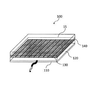
[0021]
A preferred embodiment of the present invention is to be described
in details with reference to the accompanying drawings.
Fig. 1 is a view illustrating a structural example of a floor
heating panel according to a preferred embodiment of the present invention.
As illustrated in Fig. 1, a floor heating panel 100 comprises a
bottom plate 110, a wiring board 120, a heat generation sheet 130, a
retaining plate 140, and a surface material 150.
[0022]
The floor heating panel 100 is a square plate and the floor heating
panel 100 comprises, in stack, the bottom plate 110, the wiring board 120,
the heat generation sheet 130, the retaining plate 140, and the surface
material 150.
9
CA 2982149 2017-10-12
[0023]
The bottom plate 110 is situated at the lowermost layer of the
floor heating panel 100 to support the floor heat panel 100 entirely. The
bottom plate 110 is formed of a sheet of plywood sized 600 mm x 600 mm x 4
mm thickness, and a not illustrated wiring hole 111 is apertured at the
central portion of the bottom plate 110, and a wiring cable 121 wired from
the wiring board 120 extends from the upper surface to the lower surface of
the bottom plate 110 and is exposed to the outside.
[0024]
The wiring board 120 is laminated over the bottom plate 110 and the
bottom plate 110 and the wiring board 120 are press bonded by an adhesive,
for example, an urethane resin adhesive suitable to bonding to a wooden
base material. The wiring board 120 is formed of a plywood sheet sized 600
mm x 600 mm x 15 mm thickness, in which a thermostat 123, a sensor 124 and
an electric fuse 125 to be described later are provided, and each of them
is connected by a wiring cable 121.
[0025]
The heat generation sheet 130 is laminated over the wiring board
120. The heat generation sheet 130 is a heat generation element sized 540
mm x 525 mm x 0.42 mm thickness, and has a plurality of heat generation
zones 131.
The heat generation sheet 130 is formed somewhat smaller than the
wiring board 120 and the retaining plate 130 and laminated so as to be
completely sandwiched between the wiring board 120 and the retaining plate
140.
CA 2982149 2017-10-12
[0026]
The retaining plate 140 is laminated so as to sandwich the heat
generation sheet 130 between the wiring board 120 and the retaining plate
140, and the wiring board 120 and the retaining plate 140 are press bonded
by an adhesive suitable to bonding to a wooden base material, for example,
a urethane resin adhesive while sandwiching the heat generation sheet 130
therebetween. The retaining plate 140 is a plywood sheet sized 600 mm x
600 mm x 9 mm thickness and the heat generation sheet 130 is fixed to the
inside of the plywood by the wiring board 120 and the retaining plate 140.
[0027]
The surface material 150 is situated at the uppermost layer of the
floor heating panel 100, and the retaining plate 140 and the surface
material 150 are press bonded, for example, by an epoxy resin type adhesive
suitable to bonding between stone and a wooden material. The surface
material 150 is formed of a stone sized 594 mm x 594 mm x 18 mm plate
thickness. Heat storing function and heat retaining function are improved
by using stone, for example, marble for the surface material 150. Further,
when the surface material 150 using the stone is warmed, far infrared rays
are emitted from the surface material 150 and the heat can reach not only
the surface but to the depth of a human body directly by the warming effect
of the far infrared rays.
[0028]
Since the floor heating panel 100 is manufactured as a unit
including the heat generation sheet 130 and the surface material 150 as the
floor material, the number of working steps can be decreased greatly in the
11
CA 2982149 2017-10-12
construction site. Thus, the total cost can be decreased.
[0029]
Further, by manufacturing the panel as the unit in a factory, the
number of construction steps applied at the working site can be decreased.
That is, the existent problem of difference in the construction quality
depending on the skill of the workers can be overcome and products of
uniform quality can be provided.
[0030]
Further, since the entire thickness of the floor heating panel 100
can be restricted to 46 mm by reducing the thickness of the heat generation
sheet 130 as thin as to 0.42 mm, and the thickness of the panel is designed
as thin as 75 mm also including the thickness of the platform 200, the
floor heating system can be provided with no substantial change for lived
in feel after construction.
[0031]
Fig. 2 illustrates a platform disposed below the floor heating
panel.
As illustrated in Fig. 2, a platform 200 comprises supporting
protrusions 210, connection portions 220, and panel fixtures 230.
[0032]
The platform 200 is a member used for a free access floor by
doubling the floor of forming a space of a predetermined height for network
wiring above a floor such as a slab and providing another floor thereover.
Further, the platform 200 may be disposed over an existent floor
300 or laid over a strong vinyl resin sheet so as not to damage the
12
CA 2982149 2017-10-12
existent floor 300
[0033]
In the platform 200, four supporting protrusions 210, for example,
square plate are arranged at four corners of a planar 600 mm x 600 mm
square plate so as to form a 600 mm x 600 mm square and connected by
connection portions 220 so as to form a cruciform gap C at a central
portion. Electric wirings used for the floor heating panel 100, network
wirings, etc. are arranged in the gap C.
Since the wirings are housed under the floor, they do not hinder
passage or life of residents and can avoid troubles such as disconnection
of the wirings.
[0034]
In addition, after arranging the electric wirings used for the
floor heating panel 100 or network wirings in the gap C, a cover may be put
so as to close the gap C thereby capable of protecting the electric wirings
or the network wirings against impact from above.
[0035]
The platforms 200 are connected such that they are in close
contact to each other, and cruciform, T-shaped, or L-shaped panel fixtures
230 are provided at four corners of the connected platforms 200. The panel
fixture 230 is formed of a plate materials of 3 mm thickness larger than
the height of the platform into a cruciform, T-shaped, or L-shaped
configuration, and a panel fixture 230 of an optional shape is selected
depending on the connection state of the platforms to be connected.
[0036]
13
CA 2982149 2017-10-12
The floor heating panel 100 is laid over the platform 200 so as to
overlap completely and the floor heating panel 100 is fixed by a panel
fixture 230. The method of fixing the floor heating panel 100 is to be
described later.
[0037]
Fig. 3 illustrates a state of disposing floor heating panels to the
platform disposed over the existent floor.
As illustrated in Fig. 3, a sheet of the floor heating panel 100 is
disposed just above a sheet of the platform 200 so as to overlap completely.
The platforms 200 are disposed such that adjacent platforms 200 and 200 are
in close contact to each other in a lattice pattern, in which the panel
fixtures 230 formed each in a cruciform, T-shaped, or L-shaped
configuration are arranged each at the intersection formed in a lattice
pattern being directed in the direction of the thickness of the platform
200
[0038]
The shape of the panel fixture 230 is optionally selected. For
instance, a panel fixture 230 formed in a T-shape is selected, in a case
where the laid platform is disposed on the side of the wall, and a panel
fixture 230 formed in the L-shape is selected in a case where the laid
platform is disposed at the corner of a room.
[0039]
The floor heating panel 100 is disposed over the platforms 200
surrounded by the panel fixtures 230, and fixed completely just above the
platform 200 by the panel fixtures 230 of floor heating panel 100.
14
CA 2982149 2017-10-12
A not illustrated wiring cable 121 is exposed from the center at
the lower surface of the floor heating panel 100 disposed over the platform
200 and exposed toward the platform 200. A gap C formed between adjacent
supporting protrusions 210 and 210 is present just below the center of the
floor heating panel 100, and the wiring cable 121 extended in the gap C is
connected to the power source.
[0040]
A gap D of 3 mm size corresponding to the thickness of the panel
fixture 230 is formed between the adjacent floor heating panels 100 and 100
laid over the upper surface of the platform 200. By pouring a sealing
material, the gap D or the gap between the floor heating panel 100 and the
wall surface can be protected against, intrusion of water or dusts through
the gap D.
[0041]
Fig. 4 is a view illustrating the heat generation sheet in details.
As illustrated in Fig. 4, the heat generation sheet 130 comprises heat
generation portions 131, a protection sheet 132, wiring cables 133 and
terminals 134.
[0042]
The heat generation portion 131 is a zonal heat generation element
that generates heat upon application of voltage. The heat generation
portion 131 is, for example, made of Japanese paper mixed with carbon
fibers. Since heat is generated not from a bundle of electric wires but by
a belt¨shaped heat generation unit 131 under application of the voltage,
heat can be emitted from a not linear but planar element.
CA 2982149 2017-10-12
[0043]
Further, since the heat generation portion 131 is zonal and,
accordingly, the surface material 150 disposed over the heat generation
sheet 130 can generate heat in a zonal manner, the amount of emission of
far infrared rays generated from the surface material 150 can be increased.
This can provide warm feeling even when the room temperature is low.
Further, since higher amount of heat emission can provide warmer feeling,
effective temperature can be increased by setting of a lowest temperature.
[0044]
Further, since the floor heating panels 100 are connected in
parallel with each other, if a portion of the floor heating panel 100 is
failed, only the failed portion can be replaced on the basis of the unit
sheet. This can improve the efficiency of the repair or the maintenance
operation.
[0045]
A plurality of heat generation area 131 arranged in parallel are
protected by the protection sheet 132 together with the wiring cables 133.
The top ends of the wiring cables 133 are attached to the terminals 134 and
connected to the wiring board 120.
[0046]
The wiring board 120 is attached from the lower surface and the
retaining plate 140 is attached from the upper surface of the heat
generation sheet 130 and bonded and laminated so as to sandwich the heat
generation sheet 130 therebetween. Thus, the heat generation sheet 130 is
protected by the plywood material.
16
CA 2982149 2017-10-12
[0047]
Fig. 5 is a view illustrating the wiring board in details.
As illustrated in Fig. 5, the wiring board 120 includes a wiring
cable 121, terminals 122, a thermostat 123, a sensor 124, an electric fuse
125, and a wiring hole 126.
[0048]
The terminals 122 are connected to terminals 134 provided to the
heat generation sheet 130 and connected by way of the wiring cable 121 to
the thermostat 123.
The thermostat 123 senses the temperature by the connected sensor
124 to control switchingly. The sensor 124 is attached to the upper
surface of the wiring board 120, the sensor 124 and the heat generation
sheet 130 are in close contact by the lamination of the heat generation
sheet 130 from the upper surface of the wiring board 120, and the sensor
124 can directly sense the temperature of the heat generation sheet 130.
[0049]
When the sensor 124 senses an abnormal temperature, the thermostat
123 interrupts the circuit. Since this can turn off the power source for
the floor heating panel 100, the floor heating panel 100 can be used safely.
[0050]
The electric fuse 125 is connected by way of the wiring cable 121
to the thermostat 123 and the power source cable. If a current exceeding a
rated level should flow due to some or other abnormality of the floor
heating panel 100, the conductor present inside the electric fuse 125 is
disconnected by melting and accident such as abnormal heating or ignition
17
CA 2982149 2017-10-12
of the floor heating panel 100 can be prevented.
[0051]
Wiring cables 121 extended in the wiring board 120 are gathered in
the wiring hole 126 formed at the central portion of the wiring board 120.
The gathered wiring cables 121 are exposed through the wiring hole 111
formed at the center of the bottom plate 110 stacked below the wiring board
120 from the lower portion of the floor heating panel 100. The exposed
wiring cable 121 is connected to the power source cable and the connected
power source cable is connected to a receptacle.
[0052]
Fig. 6 is a view illustrating connection of the floor heating
panels.
As illustrated in Fig. 6, the floor heating panels 100 are
connected to each other, connected in parallel to a not illustrated power
source by way of the wiring cables, and the laid floor heating panels are
controlled on every row by a not illustrated controller.
[0053]
For example, in the laid floor heating panel 100, hatched rows A
and blank rows B are controlled so s to be switched alternately, and heat
generation from the rows A and the rows B are switched on every
predetermined unit time. Specifically, assuming the unit time as 5 minutes
in the floor heating panels, the rows A are caused to generate heat for 5
minutes and, subsequently, heat generation from the rows A is interrupted
and the rows B are caused to generate heat. After further 5 minutes, heat
generation of the rows B is interrupted and the rows A are caused to
18
CA 2982149 2017-10-12
generate heat.
By controlling heat generation while dividing the heat generating
floor heating panela into two groups, the entire floor can be warmed by a
one-half electric amount.
[0054]
By using the stone, for example, marble to the surface material 150,
the heat storing function and the heat retaining function are improved also
in a portion of the floor heating panel 100 where heat generation is
interrupted, and the temperature of the generated heat can be kept within
range of a predetermine unit time. Thus, the entire floor can be heated
efficiently by a less electric amount.
The floor heating panel 100 can provide the heat generation effect
with a less electric power and the floor heating panels 100 connected in
parallel can be coped with by one circuit up to 100 sheets (about 20 JO,
i.e., about 33 0. That is, the power source can be utilized with no
requirement for change of wiring or circuit from the power source breaker
and one receptacle can be utilized for floor heating panels 100 up to 100
sheets. Further, since the change of wiring or circuit is not required
from the power source breaker, electric construction by electric engineers
is no more necessary, which can shorten the construction period and reduce
the construction cost.
[0055]
As has been described above, an electric floor heating appliances
and an electric floor heating method not requiring electric construction,
capable of shortening the construction period, improving the maintenance
19
CA 2982149 2017-10-12
function and causing no difference for the construction quality can be
provided by utilizing the floor heating panel 100 of the present invention.
[0056]
Accordingly, in a case of disposing a floor heating system for a
floor of about 33 m2, the construction period of 4 to 5 days in the case of
using the existent construction method can be shortened to about one day
and this can greatly save the construction cost.
[0057]
Further, by constituting the floor heating panel 100 as a unit of
600 mm x 600 mm size, retrofitting construction for the floor heating
system of a small area that required high cost by large-scaled construction
so far can be coped with at a reduced cost.
[0058]
Further, since the floor heating system can be disposed easily, and
can be removed easily when the floor heating is no more necessary, floor
heating system can be utilized not as a facility requiring large-scaled
construction but can be utilized in the feel of home use electronic
appliances.
Description of Reference Numerals
[0059]
electric heating equipment
20, 80 wooden flooring
30 plywood
40 base material
CA 2982149 2017-10-12
50, 121, 133 wiring cable
60 specialized breaker
70 controller
100 floor heating panel
110 bottom plate
111, 126 wiring hole
120 wiring board
122, 134 terminal
123 thermostat
124 sensor
125 electric fuse
130 heat generation sheet
131 heat generation area
132 protection sheet
140 retaining plate
150 surface material
200 platform
210 supporting protrusion
220 connection unit
230 panel fixture
300 existent floor
C, D gap
21
CA 2982149 2017-10-12