Note: Descriptions are shown in the official language in which they were submitted.
1
Title: Riser Pressure Relief Apparatus
Description of Invention
The present invention relates to a pressure relief apparatus for use in
relation
to the drilling of a subterranean borehole for oil and/or gas production.
When drilling a subsea subterranean borehole for oil and/or gas production, it
is known to use a tubular drill string which extends down from a drilling rig
at
the ocean surface into the borehole through a wellhead mounted at the ocean
floor. The drill string has a drill bit mounted at its lowermost end and
drilling
may be achieved by rotating the drill string using a top drive mounted on the
drilling rig, or by rotating the drill bit using a downhole motor at the
remote end
of the drill string. A tubular riser is mounted on a blowout preventer (BOP)
provided at the top of the wellhead, and extends generally vertically upwardly
to the ocean surface, whilst the drill string extends down the riser into the
borehole.
During drilling, a fluid (known as drilling mud) is pumped down the inside of
the
tubular drill string, through the drill bit, and circulated continuously back
to
surface via the drilled space between the borehole and the drill string
(referred
to as the wellbore annulus), and between the riser and the drill string
(referred
to as the riser annulus). The riser thus provides a flow conduit for the
drilling
fluid and cuttings returns to be returned to the surface to the rig's fluid
treatment system.
Traditionally deepwater drilling risers were designed as a conduit for
transporting well bore returns to the rig during conventional drilling
operations
or for diverting returns overboard during conventional well control in the
event
of a shallow gas kick or an influx escaping past the subsea BOP. In such
Date Recue/Date Received 2022-08-29
CA 02982694 2017-10-13
WO 2016/166533 PCT/GB2016/051035
2
systems, the riser is designed as a flow conduit that is open to atmospheric
pressure and is not a pressure containment system.
Since the development of riser flow control drilling systems, a drilling
operation
is now able to apply a safe amount of back pressure to the riser for the
purposes of managed pressure drilling or reducing peak gas flow rates in a
riser gas event. A riser flow control system consists of a pressure control
manifold on the rig and a riser sealing device that diverts returns to the
pressure control manifold. Where the riser is used in this way, there is a
need
to include a continuously available pressure relief system which provides an
alternative flow path out of the riser for drilling returns so that the
weakest link
in the riser system is not over-pressured in the event of a control system
failure, an operational error or a blockage in the conduit normally
transporting
riser returns to the rig.
Electrically operated pressure relief systems which use a PLC and pressure
transducer to signal the actuator of the pressure relief valve are known, and
disclosed in US4,636,934 and US 2011/0098946, for example. In the event of
an umbilical failure, or a failure of the electronic control system, the
electrical
communication required to operate such a system may be lost, and this can
cause the system to be unavailable when needed or result in an unintended
actuation (opening) of the pressure relief valve. An unintended actuation can
cause an environmental hazard by diverting oil based drilling mud overboard
unnecessarily (because there was no over-pressure event to begin with).
Alternatively, a lack of system availability during a riser over-pressure
event
can cause the riser to burst through resulting in danger to the rig crew as
well
as an environmental hazard. To avoid this, the system must be provided with
full redundancy, which involves providing multiple umbilicals, PLCs, pressure
transducers, etc at significant cost.
CA 02982694 2017-10-13
WO 2016/166533 PCT/GB2016/051035
3
The present invention relates to an improved apparatus for automatically
relieving excessive fluid pressure in the riser annulus in the event that the
pressure of fluid in the riser exceeds a predetermined amount.
According to the invention we provide a riser pressure relief apparatus
comprising a tubular riser having a main body enclosing a main passage and a
side port extending through the main body to connect the main passage with
the exterior of the riser, a pressure relief valve including a valve member
which
is movable between a first position in which the valve member substantially
prevents flow of fluid through the side port and a second position in which
flow
of fluid through the side port is permitted, an actuator which is operable to
move the valve member from the first position to the second position by the
supply of pressurised fluid to an open port of the actuator, a source of
pressurised fluid, and a pilot valve assembly, the pilot valve assembly being
connected to the source of pressurised fluid and being movable between a first
configuration in which flow of fluid from the source of pressurised fluid to
open
port of the actuator is substantially prevented and a second configuration in
which flow of fluid from the source of pressurised fluid to the open port of
the
actuator is permitted, wherein the pilot valve assembly includes a valve part
which is fluidly connected to the main passage of the riser and moves from a
first position to a second position when the fluid pressure in the main
passage
of the riser exceeds a predetermined amount, movement of the valve part from
the first position to the second position causing the pilot valve assembly to
move from the first configuration to the second configuration, or vice versa,
i.e.
in the alternative, movement of the valve part from the first position to the
second position causing the pilot valve assembly to move from the second
configuration to the first configuration.
Advantageously, movement of the valve part from the first positon to the
second position causes the pilot valve assembly to move from the first
configuration to the second configuration.
CA 02982694 2017-10-13
WO 2016/166533 PCT/GB2016/051035
4
In one embodiment the valve member of the pressure relief valve is rotatable
between the first position and the second position.
In one embodiment, the pressure relief valve is a ball valve.
In one embodiment, the actuator is configured such that the valve member of
the pressure relief valve is movable from the second position to the first
position by the supply of pressurised fluid to a close port of the actuator.
In
this case, the actuator may be configured such that if the fluid pressure at
the
open port exceeds the fluid pressure at the close port by a predetermined
amount the actuator moves the valve member from the first position to the
second position, whilst if the fluid pressure at the close port exceeds the
fluid
pressure at the open port by a predetermined amount, the actuator moves the
valve member from the second position to the first position.
In one embodiment, the source of pressurised fluid is an accumulator bottle.
In one embodiment, the source of pressurised fluid and pilot valve are
provided adjacent to the pressure relief valve.
In one embodiment, the source of pressurised fluid and pilot valve are
provided downstream of a connector whereby the source of pressurised fluid
may be connected to an umbilical. As such, in the event of an umbilical
failure, the pilot valve and source of pressurised fluid are available to
operate
the pressure relief valve.
In one embodiment, the fluid in the source of pressurised fluid is hydraulic
fluid.
In one embodiment, the valve part of the pilot valve assembly may be a piston
which has a face which is exposed to the fluid pressure in the main passage of
the riser.
CA 02982694 2017-10-13
WO 2016/166533 PCT/GB2016/051035
In one embodiment, the pilot valve assembly is provided with a resilient
biasing element which exerts a force on the valve part urging it into the
first
position.
In one embodiment, the source of pressurised fluid is a local source of
5 pressurised fluid and the pressure relief apparatus further comprises a
fluid
flow line for connection to a remote source of pressurised fluid. In this
case,
the fluid flow line may extend to the local source of pressurised fluid.
There may be a non-return valve provided in the fluid flow line, the non-
return
valve valve being operable to permit flow of fluid along the fluid flow line
towards the local source of pressurised fluid whilst preventing flow of fluid
along the fluid flow line in the opposite direction.
The pilot valve assembly may include a control inlet for an external control
signal, and be operable to move from the first configuration to the second
configuration when the valve part is on the first position on receipt of an
external control signal at the control inlet.
The control inlet may be for an electrical control signal or for a fluid
pressure
control signal.
The pilot valve assembly may include a pilot valve having the valve part.
The pilot valve assembly may include a control valve which moves from a rest
position in which flow of fluid from the source of pressurised fluid to the
open
port of the actuator is substantially prevented to an active position in which
flow of fluid from the source of pressurised fluid to the open port of the
actuator
is permitted on receipt of the external control signal.
The control valve may be provided with a first port which is connected to the
source of pressurised fluid via a flow line which does not contain the pilot
valve, and a second port which is connected to the open chamber via a flow
line which does not contain the pilot valve, and a valve member which is
CA 02982694 2017-10-13
WO 2016/166533 PCT/GB2016/051035
6
movable between a first position in which flow of fluid between the first port
and the second port is permitted, and a second position in which flow of fluid
between the first port and the second port is substantially prevented.
The control valve may be provided with an electrically operable actuator which
moves it from its rest position to its open position when an electrical
control
signal is supplied to the actuator.
Alternatively, the control valve may be a pilot operated valve with an
actuator
to which the control inlet is connected, the control valve being configured
such
that it moves from its rest position to its active position when the fluid
pressure
.. at the control inlet exceeds a predetermined level.
The control valve may be operable to connect the open chamber of the
actuator to a low pressure region.
The control valve may connect the open chamber of the actuator to a low
pressure region when the control valve is in its rest position.
The actuator may be configured such that the valve member of the pressure
relief valve is movable from the second position to the first position by the
supply of pressurised fluid to a close port of the actuator.
The actuator may be configured such that if the fluid pressure at the open
port
exceeds the fluid pressure at the close port by a predetermined amount the
actuator moves the valve member from the first position to the second
position, whilst if the fluid pressure at the close port exceeds the fluid
pressure
at the open port by a predetermined amount, the actuator moves the valve
member from the second position to the first position.
The pilot valve assembly may be configured to allow flow of fluid from the
source of pressurised fluid to the close port and to connect the open port of
the
actuator to a low pressure region when the pilot valve assembly is in the
first
configuration.
CA 02982694 2017-10-13
WO 2016/166533 PCT/GB2016/051035
7
The control valve may be movable to a close position in which the close port
of
the actuator is connected to the source of pressurised fluid whilst the open
port
of the actuator is connected to a low pressure region.
The control valve may be provided with an electrically operable actuator which
moves it from its rest position to its close position when electrical power is
supplied to the actuator.
Embodiments of the invention are described, by way of example only, with
reference to the accompanying figures of which,
FIGURE 1 shows a schematic illustration of a first embodiment of riser
pressure relief apparatus according to the invention in the normal closed
position,
FIGURE 2 shows a schematic illustration of the embodiment of riser pressure
relief apparatus illustrated in Figure 1 in the automatic open position,
FIGURE 3 shows a schematic illustration of the embodiment of riser pressure
relief apparatus illustrated in Figure 1 in the electronically initiated open
position,
FIGURE 4 shows a schematic illustration of the embodiment of riser pressure
relief apparatus illustrated in Figure 1 in the return to close position,
FIGURE 5 shows a schematic illustration of a second, alternative embodiment
of riser pressure relief apparatus according to the invention, in the normal
closed configuration,
FIGURE 6 shows a schematic illustration of the embodiment of riser pressure
relief apparatus illustrated in Figure 5 in the open position under surface
control,
CA 02982694 2017-10-13
WO 2016/166533 PCT/GB2016/051035
8
FIGURE 7 shows a schematic illustration of the embodiment of riser pressure
relief apparatus illustrated in Figure 5 in the open position,
FIGURE 8 shows a schematic illustration of a redundant system including the
first embodiment of pressure relief apparatus,
FIGURE 9 shows a schematic illustration of a redundant system including the
second embodiment of pressure relief apparatus.
The figures illustrate embodiments of riser pressure relief apparatus which
are
intended to be used in connection with a tubular riser for use in drilling a
subsea wellbore for oil and/or gas production. The riser has a main body
enclosing a main passage and a side port extending through the main body to
connect the main passage to the exterior of the riser.
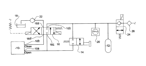
Referring now to Figure 1 there is shown a schematic illustration of a first
embodiment of riser pressure relief apparatus in a normal closed position. The
pressure relief apparatus includes a pressure relief valve 10 which is, in
use,
mounted on the riser, and which is a valve member which is movable between
a first position in which the valve member substantially prevents flow of
fluid
through the side port and a second position in which flow of fluid through the
side port is permitted. The pressure relief valve may be mounted directly on
the riser, or in a fluid flow passage which extends from the side port. The
pressure relief valve further includes an actuator which is operable to move
the
valve member from the first position to the second position by the supply of
pressurised fluid to an open port 10a in the actuator.
In one embodiment, the valve rotates between the first position and second
position.
In a preferred embodiment of the invention, the pressure relief valve 10 is a
ball valve. It should be appreciated, however, that any other suitable
configuration of valve could be used.
CA 02982694 2017-10-13
WO 2016/166533 PCT/GB2016/051035
9
The pressure relief apparatus further includes a source of pressurised fluid
for
supply to the open port of the pressure relief valve. In this embodiment of
the
invention, the source of pressurised fluid is an accumulator bottle 12, but
may
equally be any other form of pressure vessel.
Advantageously, the
accumulator bottle is located as close as possible to the actuator of the
pressure relief valve 10 to minimise the response time of the pressure relief
valve 10.
The accumulator bottle 12 is connected to the open port of the pressure relief
valve 10 via a pressure operated spring biased pilot valve 14. The pilot valve
14 includes a resilient biasing element (spring) which biases the pilot valve
14
to a closed position in which flow of fluid from the accumulator bottle 12 to
the
open port of the pressure relief valve 10. The pilot valve 14 is movable
against
the biasing force of the spring to an open position in which the accumulator
bottle 12 is connected to the open chamber 10a of the pressure relief valve
actuator. The pilot valve 14 has an actuator with a face which is, in use, in
pressure communication with the fluid in the main passage of the riser, the
fluid pressure in the riser acting to urge the actuator against the biasing
force
of the spring. When the fluid pressure in the riser exceeds a predetermined
value, the actuator can overcome the biasing force of the spring to move the
.. pilot valve 14 to the open position. In one embodiment of the invention,
the
actuator comprises a piston movably mounted in a cylinder.
The resilient biasing element may comprise a replaceable spring cartridge,
and so the pressure at which the pilot valve 14 moves from the closed position
to the open position may be adjusted by replacing the spring cartridge with a
spring rated to withstand the desired pressure before compressing.
The pressure relief system is also provided with a control valve 16. The
control valve 16 is a three position valve which has a first port 16a which is
connected to a fluid reservoir 18, a second port 16b which is connected to a
line to the accumulator bottle 18, a third port 16c which is connected to the
line
CA 02982694 2017-10-13
WO 2016/166533 PCT/GB2016/051035
between the pilot valve 14 and the open port 10a of the pressure relief valve
actuator, and a fourth port 16d which is connected to the close port 10b of
the
pressure relief valve actuator 10. The fluid reservoir 18 may be a tank
located
at surface. Alternatively, the first port 16a may simply vent into the sea.
5 The control valve 16 is biased to a rest position in which the second
port 16b
and third port 16c are closed, whilst the first port 16a is connected to the
fourth
port 16d. As such, when the control valve 16 is in the rest position the close
port 10b of the pressure relief valve actuator is connected to the fluid
reservoir
18.
10 Whilst the control valve 16 may be hydraulically (or pilot) operated, in
this
embodiment it is an electrically operated valve. The control valve 16 is
provided with a first electrically operated actuator such as a solenoid or
piezoelectric element which, when charged, moves the control valve 16 from
the rest position to an open position in which the second port 16b is
connected
to the third port 16c, and the first port 16a is connected to the fourth port
16d.
As such, when the control valve 16 is in the open position the close port 10b
of
the pressure relief valve 10 is connected to the fluid reservoir 18 whilst the
open port 10a is connected to the accumulator bottle 12. The control valve 16
is also provided with a second electrically operated actuator such as a
solenoid or piezoelectric element which, when charged, moves the control
valve 16 from the rest configuration to an close position in which the first
port
16a is connected to the third port 16c and the second port 16b is connected to
the fourth port 16d. As such, when the control valve 16 is in the close
position,
the close port 10b of the pressure relief valve actuator is connected to the
accumulator bottle 12 whilst the open port 10a is connected to the fluid
reservoir 18.
In this example, a pressure transducer 20 is provided to measure the fluid
pressure in the line between the accumulator bottle 12 and the pilot valve 14.
This may be used for monitoring of the system pressure, and periodic system
CA 02982694 2017-10-13
WO 2016/166533 PCT/GB2016/051035
11
integrity checks. It will be appreciated, however, that the pressure relief
valve
can be actuated without the availability of pressure transducers.
In this example a non-return valve 22 is provided in the line between the
fluid
reservoir 18 and the first port 16a of the control valve 16.
5 Pressurised fluid is supplied to the accumulator bottle 12 by means of an
umbilical connection to a fluid pump, which is typically mounted on the
drilling
rig A further non-return valve 24 is provided in the umbilical (or a line
connecting the accumulator bottle 12 to the umbilical). This is intended to
prevent the back flow of fluid from the accumulator bottle 12 in the event
that
10 the umbilical is damaged and loses pressure. As a result, the pressure
relief
apparatus does not loose pressure, and continues to function in the event of
an umbilical failure.
In this example, the further non-return valve 24 is provided which is an
electrically operated 2 position valve which is movable between a first
position
in which flow of fluid from the accumulator bottle 12 to the umbilical is
substantially prevented whilst flow of fluid from the umbilical to the
accumulator bottle is permitted, and a second position in which flow of fluid
is
permitted in both those directions. The non-return valve 24 will normally be
in its
first position, but may be moved to its second position in order to de-
pressurise the
pressure relief valve system before retrieving it from under the sea.
The system may be provided with a filter 26 in the feed line from the
umbilical into the
accumulator bottle 12 to ensure the cleanliness of the fluid entering the
control
system.
The pressure relief apparatus operates as follows.
Normally, the pressure relief apparatus is configured as illustrated in Figure
1. The
pilot valve 14 is in the closed position, and the control valve 16 is in the
rest position.
As such, the line to the open port 10a of the pressure relief valve 10 is
closed, and the
close port 10b is connected to the reservoir 18.
CA 02982694 2017-10-13
WO 2016/166533 PCT/GB2016/051035
12
If the fluid pressure in the riser exceeds the predetermined level, the pilot
valve 14
moves to the open position, whilst the control valve 16 is maintained in its
rest
position, as illustrated in Figure 2. Fluid flows from the accumulator bottle
12 through
the pilot valve 14 to the open port 10a of the pressure relief valve 10, and
causes the
actuator to move the pressure relief valve from the closed position to the
open
position. The fluid pressure in the riser may then be relieved by the flow of
fluid out of
the riser through the side port. Fluid flowing through the side port is
typically vented
to a safe location away from the drilling rig. Fluid is typically vented
overboard via
port or starboard diverter lines as done with traditional overboard lines.
Another
option would be to route the flow to a mud gas separator on the drilling rig.
When the pressure in the riser drops to below the predetermined level, the
pilot valve
14 returns to its closed position. The open port 10a is therefore closed, with
the fluid
pressure from the accumulator bottle 12 maintained within the actuator. The
pressure
relief valve 10 therefore remains in its open position.
The pressure relief valve 10 may also be opened by a user even if the pressure
in the
riser has not exceeded the predetermined level required to move the piston
actuator
of the pilot valve 14. To achieve this, electrical power is supplied to the
first
electrically operated actuator of the control valve 16 to move the control
valve 16 to its
open position in which the close port 10b of the pressure relief valve 10
remains
connected to the reservoir 18 whilst the open port 10a is connected to the
accumulator bottle 12 via the control valve 16. This is illustrated in Figure
3.
Pressurised fluid from the accumulator bottle 12 thus flows to the open port
10a and
operates the actuator to open the pressure relief valve 10.
In order to close the pressure relief valve 10 after either automatic
operation in an
overpressure event, or after electronic opening using control valve 16, it is
necessary
to energise the control valve 16, by supply of power to the second
electrically
operated actuator, to move it to the close position, as illustrated in Figure
4. The
open port 10a of the pressure relief valve 10 is connected to the reservoir
18, thus
relieving the fluid pressure at the open port 10a, whilst the close port 10b
is
connected to the accumulator bottle 12. The supply of pressurised fluid from
the
accumulator bottle 12 to the close port 10b of the pressure relief valve 10
operates
the actuator to move the pressure relief valve 10 to the closed position, thus
sealing
CA 02982694 2017-10-13
WO 2016/166533 PCT/GB2016/051035
13
the riser once more. Once the pressure relief valve 10 is closed, the supply
of
electrical power to the control valve 16 can cease, so that the control valve
16 returns
to its rest position.
An alternative embodiment of pressure relief apparatus is illustrated in
Figures 5 and
6
This embodiment of pressure relief apparatus has many features in common
with the pressure relief apparatus illustrated in Figures 1 to 4, and the same
reference numerals have been used in relation to these common parts. The
information set out in the description relating to Figures 1 to 4 about these
common parts applies equally to the equivalent parts in the embodiment
illustrated in Figures 5 and 6.
The pressure relief apparatus illustrated in Figures 5 and 6 includes a
pressure
relief valve 10 which is, in use, mounted on the riser, and which is a valve
member which is movable between a first position in which the valve member
substantially prevents flow of fluid through the side port and a second
position
in which flow of fluid through the side port is permitted. The pressure relief
valve 10 further includes an actuator which is operable to move the valve
member from the first position to the second position by the supply of
pressurised fluid to an open port 10a in the actuator.
The pressure relief apparatus further includes a source of pressurised fluid
for
supply to the open port of the pressure relief valve, which, in this
embodiment
of the invention, is an accumulator bottle 12. The pressure relief system also
includes a pressure operated spring biased pilot valve 14' with a resilient
biasing element (spring) which biases the pilot valve 14' to a closed
position.
The pilot valve 14 has a piston actuator with a face which is, in use, in
pressure communication with the fluid in the main passage of the riser, the
fluid pressure in the riser acting to urge the piston against the biasing
force of
the spring. When the fluid pressure in the riser exceeds a predetermined
CA 02982694 2017-10-13
WO 2016/166533 PCT/GB2016/051035
14
value, the piston actuator can overcome the biasing force of the spring to
move the pilot valve 14' to an open position.
The configuration of the pilot valve 14' is, however, slightly different to
the
configuration of the pilot valve 14 in the embodiment of the invention
described
in relation to Figures 1 to 4. Specifically, the pilot valve 14' has a first
port 14a'
which is connected to the accumulator bottle 12, a second port 14b' which is
connected to the control actuators 28, 30 of two 2 position 3 way pilot
operated
valves 32, 34 (hereinafter referred to as the auxiliary pilot valves 32, 34),
and a
third port 14c' which is blocked. When the pilot valve 14' is in the closed
position, the first port 14a' is closed whilst the second port 14b' is
connected to
the third port 14c'. When the pilot valve 14' is in the open position, the
first
port 14a' is connected to the second port 14b', and the third port 14c' is
closed.
The auxiliary pilot valves 32, 34 are each biased to a rest position by means
of
a resilient biasing element such as a spring, and are movable from the rest
position to an active position by the supply of pressurised fluid to their
respective actuator 28, 30. The auxiliary pilot valves 32, 34 each have a
first
port 32a, 34a which is connected to the accumulator bottle 12, a second port
32b, 34b which is connected to the actuator of the pressure relief valve 10,
and a third port 32c, 34c which is connected to a drain line A which extends
to
either a pressurised fluid reservoir via the umbilical, or to an overboard
vent
point.The second port 32b of the first auxiliary pilot valve 32 is connected
to
the open port 10a of the pressure relief valve actuator, whilst the second
port
34b of the second auxiliary pilot valve 34 is connected to the close port 10b
of
the pressure relief valve actuator.
When the first auxiliary pilot valve 32 is in the rest position, the third
port 32c is
connected to the second port 32b whilst the first port 32a is closed, whilst
when it is in the active position, the first port 32a is connected to the
second
port 32b, and the third port 32c is closed. In contrast, when the second
CA 02982694 2017-10-13
WO 2016/166533
PCT/GB2016/051035
auxiliary pilot valve 34 is in the rest position, the first port 34a is
connected to
the second port 34b whilst the third port 34c is closed, whilst when it is in
the
active position, the first port 32a is closed and the third port 34c is
connected
to the second port 34b.
5 In
this example, a pressure transducer 20 is provided to measure the fluid
pressure in the line between the accumulator bottle 12 and the pilot valve
14'.
Pressurised fluid is supplied to the accumulator bottle 12 by means of an
umbilical connection to a source of high pressure fluid ¨ typically a fluid
pump,
which is mounted on the drilling rig. A non-return valve 24 is provided in the
10 line B
connecting the accumulator bottle 12 to the high pressure line of the
umbilical). This is intended to prevent the back flow of fluid from the
accumulator bottle 12 in the event that the umbilical is damaged and loses
pressure. As a result, the pressure relief apparatus does not lose pressure,
and continues to function, in the event of an umbilical failure.
15 In
this example, the non-return valve 24 is a pilot operated 2 position valve
which is movable between a first position in which flow of fluid from the
accumulator bottle 12 to the umbilical is substantially prevented whilst flow
of
fluid from the umbilical to the accumulator bottle 12 is permitted, and a
second
position in which flow of fluid is permitted in both those directions. This
non-
return valve 24 is normally in the first position, but it includes a fluid
pressure
operated actuator and may be moved from the first position to the second
position by the supply of pressurised fluid to the actuator to de-pressurise
the
system prior to its retrieval from beneath the sea. It will be appreciated,
however,
that this valve 24' could equally be electrically operated.
As with the embodiment of the invention described in relation to Figures 1 to
4, the
system may be provided with a filter in the feed line from the umbilical into
the
accumulator bottle 12 to ensure the cleanliness of the fluid entering the
control
system.
CA 02982694 2017-10-13
WO 2016/166533 PCT/GB2016/051035
16
The line between the actuators 28, 30 of the auxiliary pilot valves 32, 34 and
the second port 14b' of the pilot valve 14' is also connected to a control
line C
via a further non-return valve 36. The control line C is connected to a
surface
control line in the umbilical. The further non-return valve 36 is a pilot
operated
2 position valve which is movable between a first position in which flow of
fluid
along the control line from the line between the actuators 28, 30 and the
pilot
valve 14' to the umbilical is substantially prevented whilst flow of fluid
along the
control line from the umbilical to the line between the actuators 28, 30 and
the
pilot valve 14' is permitted, and a second position in which flow of fluid is
permitted in both those directions.
The pilot non-return valve 36 has an actuator which is connected to the line B
from
the umbilical to the accumulator bottle 12 upstream of the non-return valve 24
(i.e.
between the non-return valve 24 and the connection to the umbilical). The
pilot non-
return valve 36 includes a resilient biasing element which biases it to the
first position.
Its actuator is configured such that when the pressurised fluid is supplied to
the
actuator of the pilot non-return valve 36, i.e. when the line from the
umbilical to the
accumulator bottle 12 is pressurised, the pilot non-return valve 36 is
maintained in its
second position (two way flow permitted), and returns to its first position
when the
fluid pressure in the line from the umbilical to the accumulator bottle 12
falls to a level
which is insufficient to overcome the biasing force of the resilient biasing
element.
A pressure release line D connects the control line C to a fluid reservoir (or
other low
pressure region) via an ROV-operable drain valve 38. This valve is normally
closed
to contain fluid in the control line C, but may be opened by an ROV to allow
flow of
fluid from the control line C to the fluid reservoir.
The embodiment of pressure relief apparatus illustrated in Figures 5 and 6 may
be
operated as follows.
Normally, the pressure relief apparatus is configured as illustrated in Figure
5. The
actuator of the umbilical non-return valve 24 is not pressurised so this valve
is in its
first position, and therefore permits flow in one direction only. The pilot
valve 14 is in
the closed position, and as such the lines to the actuators 28, 30 of the
auxiliary pilot
CA 02982694 2017-10-13
WO 2016/166533 PCT/GB2016/051035
17
valves 32, 34 are closed at the pilot valve 14'. Whilst the connection between
line B
and the high pressure line in the umbilical is present, the further non-return
valve is in
its second position (two way flow), as illustrated in Figure 5. If, however,
the
connection to the umbilical is damaged or lost with the result that the supply
of high
pressure fluid to line B is lost, the further non-return valve 36 will move to
its first
position. In either case, as the control line C is not pressurised, there is
no supply of
pressurised fluid to the actuators 28, 30 of the auxiliary pilot valves 32,
34. As a
result, the auxiliary pilot valves 32, 34 are in their rest positions, and the
open port
10a of the pressure relief valve actuator is connected to the drain line A by
the first
auxiliary pilot valve 32 and the close port 10b of the pressure relief valve
actuator is
connected to the accumulator 12 via the second auxiliary pilot valve 34. The
pressure
relief valve 10 is therefore in its closed position.
Surface control of the pressure relief valve 10 via the umbilical, in the
absence of
excess pressure in the riser, can be achieved as follows. With the connection
to the
umbilical in tact, line B is pressurised, and so the further non-return valve
is in its
second position (two way flow). The pilot valve 14 remains in its closed
position, but
pressurised fluid is supplied to actuators 28, 30 of the auxiliary pilot
valves 32, 34 via
the control line C and the umbilical control line. This fluid is pressurised
to such an
extent that the auxiliary pilot valves 32, 34 move from their rest positions
to their
.. active positions in which the open port 10a of the pressure relief valve
actuator is
connected to the accumulator bottle 12 by the first auxiliary pilot valve 32
and the
close port 10b of the pressure relief valve actuator is connected to the drain
line A via
the second auxiliary pilot valve 34. The pressure relief valve 10 therefore
moves to its
open position. This is illustrated in Figure 6. The pressure relief valve 10
can be
returned to its closed position by exhausting the control line C via the
umbilical control
line.
If, whilst the control line C is pressurised, the pressure in the riser
continues to rise,
and rises to such an extent that the pilot valve 14' is moved to its open
position, the
pressure supplied to the actuators 28, 30 of the auxiliary pilot valves 32, 34
is
maintained, and the pressure relief valve 10 remains open.
CA 02982694 2017-10-13
WO 2016/166533 PCT/GB2016/051035
18
If the connection to the umbilical (and hence the possibility of surface
control) is lost,
the pressure relief valve will be opened automatically in the event of riser
over-
pressure by means of the pilot valve 14'.
In this case, as the pressure in line B upstream of the non-return valve 24 is
lost, the
further non-return valve 36 moves to its first position in which return flow
through the
valve 36 is prevented. If the fluid pressure in the riser exceeds the
predetermined
level, the pilot valve 14' moves to the open position. Fluid flows from the
accumulator
bottle 12 through the pilot valve 14' to the actuators 28, 30 of the auxiliary
pilot valves
32, 34 causing them to move from their rest positions to their active
positions. As
described above, the further non-return valve 36 is in its first position, and
thus retains
the pressure in the actuators 28, 30 of the auxiliary pilot valves 32, 34.
This fluid is
pressurised to such an extent that the auxiliary pilot valves 32, 34 move from
their
rest positions to their active positions in which the open port 10a of the
pressure relief
valve actuator is connected to the accumulator bottle 12 by the first
auxiliary pilot
valve 32 and the close port 10b of the pressure relief valve actuator is
connected to
the drain line A via the second auxiliary pilot valve 34. This is illustrated
in Figure
7.The resulting flow of fluid from the accumulator bottle 12 to the open port
10a and
concomitant exhausting of fluid from the close port 10b causes the actuator to
move
the pressure relief valve from the closed position to the open position. The
fluid
pressure in the riser may then be relieved by the flow of fluid out of the
riser through
the side port. Fluid flowing through the side port is typically vented to a
safe location
away from the drilling rig as described in relation to the embodiment shown in
Figures
1 ¨4.
When the pressure in the riser drops to below the predetermined level, the
pilot valve
14' returns to its closed position. The pilot pressure acting on the actuators
28, 30 of
the auxiliary pilot valves 32, 34 is trapped by the further non-return valve
36, however.
To release this pilot pressure, an ROV is employed to open the drain valve 38,
thus
allowing the pilot pressure to drain from the control line C via the pressure
release line
D. As a result, the auxiliary pilot valves 32, 34 return their rest positions,
and the open
port 10a of the pressure relief valve actuator is connected to the drain line
A by the
first auxiliary pilot valve 32 and the close port 10b of the pressure relief
valve actuator
is connected to the accumulator 12 via the second auxiliary pilot valve 34.
Flow of
CA 02982694 2017-10-13
WO 2016/166533 PCT/GB2016/051035
19
fluid from the accumulator bottle 12 to the close port 10b of the pressure
relief valve
actuator moves the pressure relief valve 10 from the open position to the
closed
position. It will be appreciated from the above description that an advantage
of the
proposed systems is that opening of the pressure relief valve is completely
automatic
in the event of riser over-pressure. It does not rely on the correct
functioning of any
electrical or electronic equipment (compared with systems which utilise
electrical
valves operating based on the reading of an electronic pressure sensor), and
cannot
be electronically deactivated or overridden by a user accidentally altering
the pressure
relief set point to a dangerously high level. Even if the system is set up
such that the
set point for pressure relief can be set electronically (for example, in the
embodiment
illustrated in Figures 1 to 4, by providing for automatic, electronic opening
using the
electrical control valve 16 based on a reading from a pressure transducer in
the riser),
the pilot valve 14 will always open at the pressure determined by the
compressibility
of its spring, irrespective of what set-point has been set electronically, or,
indeed, if
the electronic control system is functioning correctly. As such, there is no
need to set
the system to automatically open the pressure relief valve 10 in the event of
an
electronic systems failure.
The use of a ball valve as the pressure relief valve may be advantageous as
such
valves can reseal in a reliable fashion without maintenance, parts replacement
or
retrieval.
Advantageously, the riser will be provided with two identical pressure relief
valves 10
and associated control apparatus to provide redundancy should one of the
systems
fail. Examples of how such redundant systems may be configured are illustrated
in
Figures 7 and 8. Figure 7 shows a redundant riser pressure relief system
including
two of the apparatus described above in relation to Figures 1 to 4, whilst the
system
shown in Figure 8 includes the embodiments described in relation to Figures 5
and 6.
When used in this specification and claims, the terms "comprises" and
"comprising" and variations thereof mean that the specified features, steps or
integers are included. The terms are not to be interpreted to exclude the
presence of other features, steps or components.
CA 02982694 2017-10-13
WO 2016/166533 PCT/GB2016/051035
The features disclosed in the foregoing description, or the following claims,
or
the accompanying drawings, expressed in their specific forms or in terms of a
means for performing the disclosed function, or a method or process for
attaining the disclosed result, as appropriate, may, separately, or in any
5 combination of such features, be utilised for realising the invention in
diverse
forms thereof.