Note: Descriptions are shown in the official language in which they were submitted.
CA 02982936 2017-10-05
WO 2016/168025 PCT/US2016/026271
ENHANCED SYSTEM AND METHOD FOR DETANGLING AND
PROTECTION OF AUTOMATIC FENDER POSITIONING SYSTEMS
CROSS-REFERENCE TO RELATED APPLICATIONS
[001] This application is a PCT of and claims priority to United States patent
application serial
number 15/054,125, titled "ENHANCED SYSTEM AND METHOD FOR REMOTELY
DEPLOYING BOAT FENDERS", filed on February 25, 2016 which is a continuation-in-
part of
United States patent application serial number 14/929,369, titled "ENHANCED
SYSTEM AND
METHOD FOR AUTOMATICALLY DEPLOYING BOAT FENDERS", filed on November 1,
2015, which claims priority to United States provisional patent application
serial number
62/153,193, titled "ENHANCED SYSTEM AND METHOD FOR AUTOMATICALLY
DEPLOYING BOAT FENDERS", filed on April 27, 2015. This application is also a
PCT of and
claims priority to United States patent application serial number 14/981,858,
titled "ENHANCED
SYSTEM AND METHOD FOR DETANGLING AND PROTECTION OF AUTOMATIC
FENDER POSITIONING SYSTEMS", filed on December 28, 2015, which is a
continuation-in-
part of United States patent application serial number 14/929,369, titled
"ENHANCED SYSTEM
AND METHOD FOR AUTOMATICALLY DEPLOYING BOAT FENDERS", filed on
November 1, 2015, which claims priority to United States provisional patent
application serial
number 62/153,193, titled "ENHANCED SYSTEM AND METHOD FOR AUTOMATICALLY
DEPLOYING BOAT FENDERS", filed on April 27, 2015. This PCT application also
claims
priority to United States provisional patent application serial number
62/148,725, titled "SYSTEM
AND METHOD FOR SAFELY AND CONVENIENTLY DEPLOYING BOAT FENDERS",
filed on April 16, 2015, and to United States provisional patent application
serial number
62/153,185, titled "ENHANCED SYSTEM AND METHOD FOR AUTOMATICALLY
DEPLOYING BOAT FENDERS 2", filed on April 27, 2015, and to United States
provisional
patent application serial number 62/157,857, titled "SYSTEM AND METHOD FOR
REDUCING THE PROFILE OF BOAT FENDER BASKETS", filed on May 6, 2015, and to
62/165,798, titled "AUTOMATIC BOAT FENDER BASKETS", filed on May 22, 2015, and
to
62/200,089, titled "AUTOMATIC BOAT FENDER LINE GUIDE, CAMERA AND MORE",
1
filed on August 2, 2015.
BACKGROUND OF THE INVENTION
Field of the Invention
[001] The disclosure relates to the field of boating, and more particularly to
the field of
deploying protective fenders for use in docking a boat.
Discussion of the State of the Art
[002] Boating, in a motorized or sail-powered craft, is both a popular
recreational activity and
the foundation of the seafood industry. The operator of the craft must be able
to navigate it
safely and also to dock it safely, whether at a stationary, land-based dock,
next to another boat,
or at some other, similar large adjacent object (any and all of which are
hereinafter referred to
as a "dock"). In cases of stormy weather or large waves, deploying and
positioning the
protective boat fenders to keep the boat from violently hitting a dock can be
tricky and
dangerous.
[003] What is needed is a system and method that enables a boat operator to
safely and
conveniently deploy boat fenders when needed. What is additionally needed is a
way to extend
and retract boat fender into and out of protective stowage enclosures from
locations remote
from the placement of at least some of those fenders, for added safety and
convenience. Further
needed in other cases is a way to extend and retract boat fenders using a
motor-driven
mechanism, for even greater added safety and convenience. Further needed is a
system and
method enabling a user to control these fenders from a mobile computing
device, such as a
smartphone or tablet. Additionally needed is a system and method to alert the
user to deploy
the boat's fenders when the boat is on a trajectory that leads to a previously
visited dock and, in
some cases, to deploy the fenders automatically, all based upon a global
positioning system
(GPS) location of the boat.
SUMMARY OF THE INVENTION
[004] The inventor has conceived and reduced to practice, in a preferred
embodiment of the
invention, an enhanced system and various methods for remotely deploying boat
fenders.
2
CA 2982936 2019-02-13
CA 02982936 2017-10-05
WO 2016/168025 PCT/US2016/026271
[IX)61 According to a preferred embodiment of the invention, a system with a
basket for stowing
a boat fender, the basket attached to a vessel, the basket having an opening
for threading through
a line, the line being attached to the fender, the line operable to pull up
the fender into the
basket through a second opening at the bottom of the basket and where a
moveable bar exists
within the basket across its opening directly above the fender, the bar having
a small opening for
guiding the line, which passes through it, the bar being moveable along the
cylindrical axis of the
basket. In a variation of the embodiment, the bar is pulled up along with the
fender into the
basket. Where the basket has at least one moveable, hinged section, the
section formed in such a
manner that when the fender is pulled up into the top of the basket, the
movable section clamps
in on the fender and secures it within the basket.
[007] In one preferred embodiment, a cleat (or auto cleat) allows the line to
be secured at any
position, the cleat attached to or near the basket, or at a convenient
location some distance from
the basket, by passing the line through one or more guide rings or pulleys,
and the fender is
raised into the basket upon leaving a dock and lowered to the correct level
manually in
preparation for docking of the boat.
10081 In another preferred embodiment, the fender is attached to the line, the
line coupled to a
winch, the winch coupled to a motor, and the motor controlled by a controller,
wherein the
controller is activated via wireline or wireless control signals. Here, the
controller may be
controlling more than one basket. The winch may draw its power from a battery,
where the
battery is the onboard power supply or the battery is separate and recharged
by a solar panel
coupled to the battery. Each basket may have its individual controller,
battery and solar panel, as
to not require any wiring between the units.
[009] The basket may be mounted with at least one hinge to a stationary part
of the boat within
the boat's outline, the hinge operable to allow the basket to swing out from
the boat's outline, for
easy deployment of the fender. Deployment of the basket may be controlled for
the swing-out
with a lever, the lever attached to a second stationary part of the boat, the
lever being used to
initiate and stop or reverse the swing-out action. The lever may also be a
hinged arm and may be
operated manually or operated with an additional motor.
[010] Alternately, the basket may be mounted on at least one stationary part
of the boat,
substantially within the boat's outline, the basket having an angle for
enabling the fender to be
3
CA 02982936 2017-10-05
WO 2016/168025 PCT/US2016/026271
lowered through an opening in the railing over the edge of the boat's board
and have an
additional slide extension at the bottom opening, the extension guiding the
fender over the edge
of the boat.
[011] According to yet another embodiment of the invention, an application on
a smart phone,
the application having access to a map system and also optionally having
access to a GPS system
of the smartphone, wherein the application may be used by a user to add
locations used by a
vessel for landing, and the user may enter a mark representing a height of
fenders to be
deployed. The system may then remember the decision of the user whether or not
and how to
deploy the fenders, or whether no preset action is desired.
[012] Finally, the enclosure may contain a camera looking outward from the
boat, the camera
supplied power by the same system that operates the fender, and the camera
coupled to provide
a video stream on request to one of the controlling computing devices,
allowing a person to
better see when approaching the docking location.
BRIEF DESCRIPTION OF THE DRAWING FIGURES
[013] The accompanying drawings illustrate several embodiments of the
invention and,
together with the description, serve to explain the principles of the
invention according to the
embodiments. One skilled in the art will recognize that the particular
embodiments illustrated in
the drawings arc merely exemplary, and are not intended to limit the scope of
the present
invention.
.. [014] Fig. 1 (PRIOR ART) is an illustration of a typical pleasure boat,
illustrating how fenders
are normally hung on a boat's railings.
[015] Fig. 2 shows an exemplary representation of an installation of manually-
deployed boat
fenders, according to a preferred embodiment of the invention.
[016] Fig. 3 shows an exemplary representation of a fender stowage basket
according to a
.. preferred embodiment of the invention.
[017] Fig. 4 shows an exemplary representation of a pulley and remote cleat
mechanism for the
safe and convenient stowage and deployment of boat fenders according to a
preferred
embodiment of the invention.
4
CA 02982936 2017-10-05
WO 2016/168025 PCT/US2016/026271
[018] Fig. 5 shows an exemplary representation of a user reminder app for boat
fender
deployment according to a preferred embodiment of the invention.
[019] Fig. 6. shows an exemplary representation of the connection of four
basket and fender
mechanisms connected by wires to a solar panel according to a preferred
embodiment of the
invention.
[020] Fig. 7 is a diagram of an exemplary solar panel assembly connected to a
basket and
fender mechanism according to a preferred embodiment of the invention.
[021] Fig. 8 is a diagram of an exemplary controller for the deployment and
retraction of
fenders according to a preferred embodiment of the invention.
.. [022] Fig. 9 is an exemplary diagram of a computer system as may be used in
the system and
methods disclosed herein.
[023] Fig. 10 is an exemplary diagram of a wireless control system for
deployment an retraction
of boat fenders as per a preferred embodiment of the invention.
[024] Fig. 11 shows a representation of an exemplary system application screen
depicting a boat
approaching a dock in a harbor, according to a preferred embodiment of the
invention.
[025] Fig. 12 shows an application screen that is exemplary of additional
application
functionality according to a preferred embodiment of the invention.
[026] Fig. 13 shows an exemplary application screen that may open when a user
has deployed
boat fenders according to a preferred embodiment of the invention.
[027] Fig. 14 shows an exemplary representation of a boat prow where the
basket is mounted
on one or more hinges according to a preferred embodiment of the invention.
[028] Fig. 15 shows an exemplary cross section of a boat with a representative
basket secured
by mounting hinges and a chute that aids in deployment according to a
preferred embodiment of
the invention.
[029] Fig. 16 shows a diagram of an alternative method to recess the basket
according to a
preferred embodiment of the invention.
[030] Fig. 17 shows an exemplary representation of an enhanced boat fender
basket according
to a preferred embodiment of the invention.
5
CA 02982936 2017-10-05
WO 2016/168025
PCT/US2016/026271
[031] Fig. 18 shows an exemplary fender deployment reminder pop-up screen
according to a
preferred embodiment of the invention.
[032] Fig. 19 shows a screenshot in which the system prompts the user whether
to remember
the decision.
[033] Fig. 20 shows an exemplary representation of two alternative methods for
protecting a
boat motor and electronic circuitry from overload due to problems with raising
a boat fender.
[034] Fig. 21 shows an exemplary representation of an approach for viewing
entanglements or
other problems preventing a boat fender from being fully raised.
[035] Fig. 22 shows a process for resolving problems with raising a fender.
[036] Fig. 23 shows a pair of embodiments with elastic members to mitigate
forces transmitted
from a fender to a mechanism of the invention.
DETAILED DESCRIPTION
[037] The inventor has conceived, and reduced to practice, an enhanced system
and method
for remotely deploying boat fenders.
[038] One or more different inventions may be described in the present
application. Further,
for one or more of the inventions described herein, numerous alternative
embodiments may be
described; it should be understood that these are presented for illustrative
purposes only. The
described embodiments are not intended to be limiting in any sense. One or
more of the
inventions may be widely applicable to numerous embodiments, as is readily
apparent from the
disclosure. In general, embodiments are described in sufficient detail to
enable those skilled in
the art to practice one or more of the inventions, and it is to be understood
that other
embodiments may be utilized and that structural, logical, software, electrical
and other changes
may be made without departing from the scope of the particular inventions.
Accordingly, those
skilled in the art will recognize that one or more of the inventions may be
practiced with various
modifications and alterations. Particular features of one or more of the
inventions may be
described with reference to one or more particular embodiments or figures that
form a part of
the present disclosure, and in which are shown, by way of illustration,
specific embodiments of
6
CA 02982936 2017-10-05
WO 2016/168025 PCT/US2016/026271
one or more of the inventions. It should be understood, however, that such
features are not
limited to usage in the one or more particular embodiments or figures with
reference to which
they are described. The present disclosure is neither a literal description of
all embodiments of
one or more of the inventions nor a listing of features of one or more of the
inventions that must
be present in all embodiments.
[039] Headings of sections provided in this patent application and the title
of this patent
application are for convenience only, and are not to be taken as limiting the
disclosure in any
way.
[040] Devices that are in connection with each other need not be continuously
connected with
each other, unless expressly specified otherwise. In addition, devices that
are in connection with
each other may connect directly or indirectly through one or more
intermediaries, logical or
physical.
[041] A description of an embodiment with several components in connection
with each other
does not imply that all such components are required. To the contrary, a
variety of optional
components may be described to illustrate a wide variety of possible
embodiments of one or
more of the inventions and in order to more fully illustrate one or more
aspects of the inventions.
Similarly, although process steps, method steps, algorithms or the like may be
described in a
sequential order, such processes, methods and algorithms may generally also
work in alternate
orders, unless specifically stated to the contrary. In other words, any
sequence or order of steps
that may be described in this patent application does not, in and of itself,
indicate a requirement
that the steps be performed in that order. The steps of described processes
may be performed in
any order practical. Further, some steps may be performed simultaneously
despite being
described or implied as occurring sequentially (e.g., because one step is
described after the other
step). Moreover, the illustration of a process by its depiction in a drawing
does not imply that the
illustrated process is exclusive of other variations and modifications
thereto, does not imply that
the illustrated process or any of its steps are necessary to one or more of
the invention(s), and
does not imply that the illustrated process is preferred. Also, steps are
generally described once
per embodiment, but this does not mean they must occur once, or that they may
only occur once
each time a process, method, or algorithm is carried out or executed. Some
steps may be omitted
7
CA 02982936 2017-10-05
WO 2016/168025 PCT/US2016/026271
in some embodiments or some occurrences, or some steps may be executed more
than once in a
given embodiment or occurrence.
[042] When a single device or article is described, it will be readily
apparent that more than
one device or article may be used in place of a single device or article.
Similarly, where more
than one device or article is described, it will be readily apparent that a
single device or article
may be used in place of the more than one device or article.
[043] The functionality or the features of a device may be alternatively
embodied by one or
more other devices that are not explicitly described as having such
functionality or features.
Thus, other embodiments of one or more of the inventions need not include the
device itself.
[044] Techniques and mechanisms described or referenced herein will sometimes
be described
in singular form for clarity. However, it should be noted that particular
embodiments include
multiple iterations of a technique or multiple manifestations of a mechanism
unless noted
otherwise. Process descriptions for computing equipment or such blocks in
figures should be
understood as representing modules, segments, or portions of code which
include one or more
executable instructions for implementing specific logical functions or steps
in the process.
Alternate implementations are included within the scope of embodiments of the
present
invention in which, for example, functions may be executed out of order from
that shown or
discussed, including substantially concurrently or in reverse order, depending
on the functionality
involved, as would be understood by those having ordinary skill in the art.
Detailed Description of Exemplary Embodiments
[045] The system and method disclosed herein uses a lift system for fenders,
with baskets
providing secure stowage for fenders when not in use. Additionally, an
application on a
smartphone may remind the crew to lower the fenders when approaching a dock
and possibly,
based on previous dockings, a reminder for a mark on the line where to cleat
or fast cleat the
line, so the fender has the appropriate height for that dock. In some cases
the application may
provide a reminder or in other cases the application may actually perform the
fender deployment
operation (as the baskets are motorized in those cases). In most cases the
fender is positioned at
the same height while docking, but in some situations different heights may be
necessary.
8
CA 02982936 2017-10-05
WO 2016/168025 PCT/US2016/026271
[046] In some cases, a basket for stowing a fender is used, that is sometimes
attached to a part
of a vessel or boat, and the basket has an opening for threading through a
line (in some cases
with a pulley), the line attached to a fender, the line operable by a user to
pull up the fender into
the basket through a second opening at the bottom of the basket. Typically,
the basket has at
.. least one moveable, hinged section, the section formed in such a manner,
that when pulling up
the fender to the top, the movable section is clamping in on the fender and
securing it. In some
cases the basket and the moveable section can be made of a rigid material such
as a metal,
suitable for marine use. In other cases a majority of the parts arc made from
a soft plastic
material suitable for molding. In yet other cases, the parts of the basket are
made of a
combination of rigid metal parts and soft plastic materials. Additionally, in
some cases a fast cleat
is provided to secure the line in at least two positions, one of which has the
fender full retracted
and at least one other having the fender deployed, and wherein the fast cleat
may be mounted in
an easy to reach location on the vessel. Further, an application for use on
smart phone can be
provided, and the application has access to a third party map system. The
application has also
access to the GPS system of the smartphone. When approaching a docking site
the application
can be used by a user to add locations used by the vessel for landing, and the
user can enter a
mark representing the height of the fenders deployed. In some cases, the
application will display
and or make heard a reminder to deploy at least one fender, and that display
will include the
previously stored height mark for deploying the fender. In yet other cases,
the basket for stowing
a fender will have a cleat or auto cleat to allow the line to be secured at
any position. In some of
these cases the cleat is attached to or near the basket. Furthermore, in some
cases the cleat can
be released with a controlled jerking of the line. In some cases the line may
be routed inside the
basket and exit from the same opening as the fender.
[047] In additional cases, the system and method disclosed herein uses wired
or wireless
communication, such as, for example, Bluetooth, to control automatic
deployment and retraction
of boat fenders. The mechanism can be powered by solar or the boat DC.
[048] In some other cases, a system may comprise a basket for lowering one or
multiple boat
fenders, with the fender attached to a line that is coupled to a winch that is
coupled to a motor,
with the motor controlled by a controller that may be activated via wireless
control signals. Power
for the motor may be drawn from a battery, which may be the onboard power
supply or,
9
CA 02982936 2017-10-05
WO 2016/168025 PCT/US2016/026271
alternatively, may be separately charged from a solar panel. Alternatively,
each basket may have
an individual controller, battery, and solar panel, not requiring any wiring
between the units.
[049] In some cases, the system and its methods enable these fenders to be
controlled from a
mobile computing device, such as a smartphone or tablet, both of which should
be considered
equivalent for all purposes here. Additionally, in some cases, based on
repeated visits, the
fenders can deploy automatically based on the GPS location of the boat and the
fact that its
trajectory leads the boat to a landing slip, berth, dock etc.
[050] In further cases, a smartphone with an app may be used to control one or
more of the
basket controllers and a multitude of automatic baskets. The app can also
control baskets based
on previous programming, without requiring user interaction, and,
additionally, based on
distance to a landing site derived from GPS data and map data, can prompt the
user for an
action and can memorize that action for future use. This app may include a
dedicated control
panel to wirelessly control one or more controllers of baskets, using
Bluetooth or Wi-Fi etc. as a
wireless protocol.
[051] In some cases, rather than a smart phone or tablet, an onboard
navigation system or
some other computerized boat system may be upgraded or extended to add the
control
functionality. This could be done via wired or wireless control of motorized
buckets. For
purposes, here, they all should be considered equivalent and a may have a GPS
enabled
computing device.
[052] In some cases, rather than mounting a basket to the railing, a basket
type tube could be
integrated into the hull of a boat, similar to a torpedo tube and with or
without an outer door
protecting the fender when not in use. It may be designed outside the
displacement section of the
boat hull, thus eliminating complicated locks on the inside, and additionally
not requiring
waterproofing of the interfaces. For purposes herein, it would be considered
essentially
equivalent.
[053] In additional cases, in a system with one or more baskets for lowering
one or more
fenders attached to a line, each basket may be mounted with one or more hinges
so the basket
can swing out from the boat's outline, for easy deployment of a fender.
Further, each basket may
be controlled for the swing-out with a lever attached to the boat and used to
initiate and stop or
reverse the swing-out action of the basket. This lever may be a hinged arm and
may be operated
CA 02982936 2017-10-05
WO 2016/168025 PCT/US2016/026271
manually or by a motor. In some cases, the basket may be mounted substantially
within the
boat's outline and angled so the fender may be lowered through an opening in
the railing over
the edge of the boat's board. The basket, in such cases, may also have an
additional slide
extension at the bottom opening to extension guide the fender over the edge of
the boat. The
basket may, in such cases, extend out through an opening in the railing to
facilitate easier
deployment of the fender, which deployment may be accomplished either manually
or with the
help of a motor, and the swing-out may be achieved with the help of an
additional motor.
[054] In some cases, the winch may feed the unused line into a small basket or
storage
compartment that will hold the unused section. In yet other cases, a spool
maybe used to wind
on and store unused sections. In yet other cases, rather than normal line or
rope, chains made of
metal and or plastic material maybe used, and the winch may have matching
grooves that garb
the chain links.
[055] In additional cases, the basket for lowering fenders has a moveable bar
across the
opening; this bar, which can move along the cylindrical axis of the basket and
is pulled up
alongside the fender into the basket, has a small opening for guiding the
line, as well as
additional openings or features for guiding itself up and down the basket.
Further, an external
force can make the basket swing back into the hull line, counteracting at
least a spring, connected
to the hinge, that moves the basket outside the hull line for normal
operations. In some cases, the
line may be coupled to a motor-driven winch, with the motor controlled by
wired or wireless
signals.
[056] In some cases, in a system with a basket and a mechanism for stowing a
boat fender,
upon retracting the fender, the system shuts off the motor if an over-current
arises due to a tangle
in the line or a catch of the fender below the basket. Upon such a shutdown of
the motor, the
system engages in a limited number of small reversals in an attempt to
detangle the line and/or
the fender and achieve a full retraction. Additionally, a camera and visual
recognition software
may be used to detect a tangle or other problem with the line or the fender,
in addition to the
current sensing. Further, upon attempting to retract the fender, the motor
shuts off if a
disturbance in the retraction motion is recognized by the visual recognition
software due to a
tangle in the line or a catch of the fender below the basket. In such cases,
the system engages in a
limited number of small reversals to attempt to detangle the line and or the
fender and achieve a
11
CA 02982936 2017-10-05
WO 2016/168025 PCT/US2016/026271
full retraction. Moreover, the current control may be used to aid the
detangling control of the
reversal of the line motion in addition to the camera. Additionally, if after
several small reversals
retraction of a fender is impossible, in some embodiments a user may be
notified of the problem,
and of the fact that a fender has not been fully retracted, thus alerting the
user to a possible need
for manual intervention.
[057] Fig. 1 (PRIOR ART) is an illustration of a typical pleasure boat 100,
illustrating how
fenders are normally hung on a boat's railings according to the prior art. Two
fenders 107a and
107b hang down from the railing, positioned with lines 108a-b held in place
with knots 109a-b on
railing 102 to protect the boat from damage when the boat makes contact with
the dock. During
a cruise, the fenders need to be lifted up and securely stowed, as otherwise
the wave action could
easily rip them off or cause them to damage the boat. Access to the railing
for purposes of
deploying and positioning fenders from the top of the boat may be difficult
and hazardous
(particularly in rough seas or inclement weather), because in many cases
access is available only
from a narrow ledge 106 via a step 110 or from the top of the boat prow 103
using window gate
105 in windshield 104, that window gate being heavy and difficult to open.
Boat prow 103 is
often of a slick material such as fiberglass coated, in some cases, with
marine paint. Further, the
surface may in many cases be wet with, in some cases, dust mixed in, and/or
the boat may be
rocking and jerking in wind and waves, making it even more slippery and more
hazardous. From
the railing a person must then lean over to deploy and position the fenders.
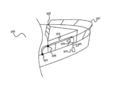
[058] Fig. 2 shows an exemplary representation of a system 200 of manually
deployed boat
fenders, with stowage baskets 204, according to a preferred embodiment of the
invention.
Windshield 202 has a center partition that can be folded away to reach the
boat prow. Attached
to railing 201 is fender basket 204, which holds fender 203 when the fender
203 is not in use
(only one fender 203 and basket 204 are shown, for purposes of clarity and
simplicity; however,
typically, multiple fenders are used). A rope, cable, or similar flexible line
205 (for purposes of
this system, rope, cable, and line all shall be considered equivalent,
irrespective of constituent
material(s)), runs from a position above basket 204, across pulley 206, to
cleat 207, which cleat
207 is used by an operator to secure line 205 in position, which position is
often predetermined
and marked on line 205. Thus fender 203 may be hauled up into basket 204 when
the boat is
undocked and taken out on the water, and fender 203 may be deployed (lowered)
when the boat
approaches a dock.
12
CA 02982936 2017-10-05
WO 2016/168025 PCT/US2016/026271
[059] Fig. 3 shows an exemplary representation of a fender stowage basket 300
as shown on
Fig. 2 according to a preferred embodiment of the invention. Attached by clamp
303 to railing
301 is a holder 310a that holds ring 304, which in turn holds basket 204, plus
a pulley (or ring)
302, via holder 310b, the pulley 302 used to redirect line 306 when it comes
up. In this example
.. two sections (or segments) 305a,b are hinged at the top with, respectively,
hinges 309c,d and
309a,b. Hinges 305a,b are attached to ring 304. When fender 307 is pulled up
on line 306 across
pulley 302, the tips of hooks 308a,b cause the extensions at the bottoms of
sections 305a,b to
clamp the fender 307 in place, as the hinge lever action causes the bottom
ends of sections
305a,b to pull in. In some cases, basket extension 305a,b may be made of
plastic; in other cases,
they may be made of some suitable material resistant to corrosion, such as,
for example, chrome-
plated wire. In yet other cases, the bottom end maybe be flaring (not
depicted), allowing for an
easier insertion of fender 307; in other cases it may be hooked inward (not
depicted), providing
additional securing of fender 307 when stowed. Also, in additional cases,
rather than two
sections, three, four or more sections maybe used.
[060] Fig. 4 shows an exemplary representation of a pulley and remote cleat
mechanism 400 for
the safe and convenient stowage and deployment of boat fenders 400 according
to a preferred
embodiment of the invention. Line 402 comes in from the basket 406 on railing
401 and goes
through pulley wheel 404, which is attached to pulley block 403. At the
pulley, line 402 is
redirected to cleat 405. In some cases, double or triple pulleys maybe used as
often more than
one fender is used. Also, instead of regular cleats, fast cleats and multi-
line fast cleats maybe used
for easier use.
[061] Fig. 5 shows an exemplary representation of a user reminder application
500 for boat
fender deployment according to a preferred embodiment of the invention. It
uses high-accuracy
marine maps such as, for example, NAVIONICSTM, to determine whether the boat
is about to
dock, and notifies the user with message 501 (and in some cases an acoustic
alert) of the position
to which the lines need to be lowered. Also shown are buttons to add new
positions "+" based on
current GPS location, to set the height, and to "edit" for modifying an
existing height, for
example, or delete a previously stored location. Further, an OK button enables
the operator to
confirm and/or close the alert and mute an acoustic signal.
13
CA 02982936 2017-10-05
WO 2016/168025 PCT/US2016/026271
[062] Fig. 6 shows an exemplary representation of a system 600 where the
connection of four
basket and fender mechanisms connected by wires to a solar panel 604 according
to a preferred
embodiment of the invention. Four baskets 602a-d are attached to railing 601.
Wires 605a-d
connect the baskets to solar panel 604, which is also attached to railing 601.
Beneath solar panel
604, and connected to it, are a controller and a battery (not shown here).
Fender 603d (only one
fender shown here, for clarity and simplicity) is shown as it may be deployed,
with multiple
dotted lines to indicate that the fender may be deployed at any of multiple
heights. It is clear that
a boat may carry more than four basket-fender units, and they arc typically
deployed all along an
engaged side of the boat, from prow to stern; however, for clarity and
simplicity, only four are
shown as positioned here.
[063] Fig. 7 is a diagram of a system 700 with a solar panel assembly
connected to a basket and
fender mechanism (as shown in 604) according to a preferred embodiment of the
invention.
Panel 701 connects to charge control unit 702. Unit 702 is an existing
commercial product that is
readily available. Often unit 702 may be integrated into a junction box at the
rear of panel 701.
Battery 703 may be any of various types of battery known in the art, such as,
for example, lead-
acid, lead-acid gel, lithium, lithium ion, LiFePO4, NiCd, NiMh, or any other
suitable type,
depending on which is best and most suitable for its situation. System
controller 704 has an
antenna 714 and wires 705a-n leading to the baskets. Exemplary basket 706,
connected to box
704 via wire 705x, contains fender 713, shown in a dotted line to indicate
that it is not externally
visible. Line 712 goes over two pulleys 710a, b to winch 709 that is attached
to motor 708. Casing
707 protects assembly elements, including 707, 709, 710a,b, 711, and 712
against water, collision,
injury of persons nearby, etc. When fender 713 is retracted, switch 711
signals to controller 704
when the fender is fully retracted. In some cases, a smaller solar cell and
smaller controller may
be mounted on the top of the basket, omitting the need for wires such as wire
705x. Typically
wire 705x uses a four-lead wire, that is, two for the motor and two for the
switch. In other cases,
instead of using a solar panel to power the system, controller 704 may be
powered from the
boat's power supply. In yet other cases, the assembly contained in case 707
may be installed
centrally and the line may be pulled as shown in Figure 2 to a location with
multiple motorized
winches. Also, in lieu of using a mechanical switch 711, optical means, both
transmissive and
reflective, may be used, or simply a change in current of the motor that the
controller can detect
and use as an indicator of too much resistance, either at the end or if fender
is caught somehow.
14
CA 02982936 2017-10-05
WO 2016/168025 PCT/US2016/026271
All these exemplary variations, and other, similar variations, shall not
depart from the spirit of the
system and method disclosed herein.
[064] Fig. 8 is a diagram of an exemplary controller for the deployment and
retraction of
fenders 800, also shown in 704, according to a preferred embodiment of the
invention. Power
supply input 802 may come from a local battery, a shipboard battery, or some
other power
source. Controller 801 has a microprocessor 806, typically a system on a chip
with memory 807
and nonvolatile memory 808, which nonvolatile memory contains software 809a-n,
including an
operating system as well as actual commands for the system. Input/output unit
810 may pair the
radio 811 with a smart phone. Radio 811 connects to microcontroller 806 as
well as to antenna
.. 812. The connection between radio 811 and a smart phone may be via, for
example, Bluetooth,
Wi-Fi, or both, as needed. Power switch unit 803 distributes power to all
these devices, as well as
controlling output power through switches 804a-n, thus enabling the winches to
extend lines to
extend or retract the fenders. Switch unit 803 also has the input sensors for
the switches in the
baskets, such as, for example, switch 711 inside casing 707, described above
in the discussion of
Figure 7, for extending or retracting the fenders.
[065] Fig. 9 is an exemplary diagram of a computer system 900 as may be used
in the system
and methods disclosed herein, according to various embodiments of the
invention. It is
exemplary of any computer that may execute code to process data. Various
modifications and
changes may be made to computer system 900 without departing from the broader
spirit and
scope of the system and method disclosed herein. CPU 901 is connected to bus
902, to which bus
is also connected memory 906, nonvolatile memory 904, display 907, I/O unit
908, and network
interface card (NIC) 916. I/0 unit 908 may, typically, be connected to
keyboard 909, pointing
device 910, hard disk 912, and real-time clock 911. NIC 916 connects to
network 914, which may
be the Internet or a local network, which local network may or may not have
connections to the
Internet. Also shown as part of system 900 is power supply unit 905 connected,
in this example,
to ac supply 906. Not shown are batteries that could be present, and many
other devices and
modifications that are well known but are not applicable to the specific novel
functions of the
current system and method disclosed herein. Also present, but not shown in
detail, as part of I/O
unit 908, for example, will local wireless connections, such as Bluetooth, Wi-
Fi, ZigBee etc.
Further, in many cases, a GPS receiver is used to provide for location
services.
CA 02982936 2017-10-05
WO 2016/168025 PCT/US2016/026271
[066] Fig. 10 is an exemplary diagram of a wireless control system 1000 for
deployment and
retraction of boat fenders, according to a preferred embodiment of the
invention. Controller
1001, which is functionally equivalent to controller 704, described above in
the discussion of Fig.
7, has an antenna 1002 and also the software and other components required to
control fender
deployment operations as previously described. Controller 1001 may connect to
a dedicated
control unit 1003, which unit may have a set of buttons 1004a-n, such as, for
example, two rows
of buttons 1004a-n as shown here. Each button has a separate assigned
function, such as
controlling the raising or lowering of one or more fenders. General controls
1005a-n may, for
example, indicate the status of certain system functions, such as, for
example, power state and the
.. state of connectivity to wireless network 1006, which network may use
Bluetooth, Wi-Fi, or some
other similar connection protocol. Controls 1035a-n may also control functions
such as raising or
lowering all fenders or certain combinations of fenders, such as all fenders
on one side, for
example. As an alternative control unit, system 1000 may use a smart phone,
such as, for
example, phone 1010, on whose touch screen 1013 the user can control the
functions of
specialized software 1011a-n. Software 1011a-n is specific to system 1000 and
typically may be
downloaded from an app store supplying software for the particular model of
phone 1010.
Software 1011a-n can communicate with controller 1001 via connection 1012,
which may be
Bluetooth, Wi-Fi, or some other similar connection protocol. Connection 1014
enables phone
1010 to communicate with geo-positioning satellites 1015a-n, using any of
various global
positioning systems (GPS) supported by phone 1010 and available currently or
in the future.
[067] Fig. 11 shows a representation of an exemplary system application screen
1100 depicting
a boat approaching a dock in a harbor according to a preferred embodiment of
the invention. In
this example, a boat 1103 is in water 1101, approaching dock 1104, which dock
extends from
land 1102. When boat 1103 comes within a certain predetermined distance from
dock 1104, an
indicator 1105 appears on application screen 1100. The boat's position, in
this example, is
determined by high-accuracy navigational mapping software (not shown here) as
mentioned in
the description of Fig. 5. Indicator 1105 enables a user to open addition
application menus with
additional functionality.
[068] Fig. 12 shows an application screen 1200, accessed using indicator 1105
that is exemplary
of additional application functionality according to a preferred embodiment of
the invention. In
this example, boat 1201, viewed from the top, approaches dock 1202. Screen
1200 shows all boat
16
CA 02982936 2017-10-05
WO 2016/168025 PCT/US2016/026271
fenders 1204a-n, of which in this example there are eight. Those fenders on
the side approaching
dock 1202 may be indicated, for example, by halo buttons, that is, buttons
showing a halo
around the fender indicating a possible user interaction. Screen 1200 may also
contain an
additional button (not shown here) that enables a user to control multiple
fenders, such as, for
example, all fenders together, all fenders on the side of the boat approaching
the dock, all front
fenders, all rear fenders, etc.
[069] Fig. 13 shows an exemplary application screen 1300 that may open when a
user has
deployed boat fenders as described in the discussion of Fig. 12, according to
a preferred
embodiment of the invention. Represented on screen 1300 is one side 1301 of
the boat, with
fenders 1302a-n. Above and below fenders 1302a-n are arrows 1303a-n,
indicating fender
movement up or down. Buttons 1304a-n give a user control of general functions,
such as, for
example, deploying all fenders to a default position or saving a manually
controlled position as a
new default position. Individual fender positions may be manually controlled
by pressing any of
arrows 1303a-n to adjust any one fender up or down as desired. When the
fenders are all
.. adjusted for a certain dock, the user could then save the fender
positioning as a new default for
this location, so the next time the user goes to approach this particular
dock, the fenders can be
deployed automatically to the saved positions when the boat comes within a
certain
predetermined distance from the dock.
[070] Fig. 14 shows an exemplary representation of a boat prow 1400 where a
basket 1402 is
mounted on one or more hinges 1403, according to a preferred embodiment of the
invention.
This figure shows many structures found at the prow of the boat, including
railing 1405, prow
1401 with cabin windows, and other features. Exemplary basket 1402 is, in this
example,
mounted behind railing 1405, with mounting hinges 1403a, b on the inside of
railing 1405. Chute
1404 is attached to basket 1402, so the fender within basket 1402 may slide
down against the boat
side. Deploying and retracting the fender may be done manually, with, for
example, a line, or by
a motor. In some cases, chute 1404 may have a small lip, so the fender can
easily be retracted
back up into basket 1402. In other cases, chute 1404 may be recessed behind
the farthest
extension of the outward vertical curve of prow 1400, thus not protruding into
the line of travel
(up and down) of the fender.
17
CA 02982936 2017-10-05
WO 2016/168025 PCT/US2016/026271
[071] Fig. 15 shows an exemplary cross section 1500 of a boat 1501 with a
representative basket
secured by mounting hinges and a chute that aids in deployment, according to a
preferred
embodiment of the invention. The outlines of boat 1501, prow section 1507 on
top, walkway
1508 behind the railing, and the hull are all, for reasons of clarity and
simplicity, very simplified.
Basket 1502, secured by mounting hinges 1503a, b, and chute 1504 are slightly
behind the
outermost part of the hull of boat 1501, because fender 1505 is heavy enough
to slip over the
edge of boat 1501 when it is deployed. Deploying and retracting fender 1505
may be done
manually, with, for example, a line, or by a motor. On the other hand, when
fender 1505 is
retracted, because there is no edge of chute 1504 protruding beyond the hull,
fender 1505 can
easily slip back up chute 1504 and into basket 1502. Outline 1506 shows an
alternative basket
1502 position, wherein basket 1502 may be hinged around the railing so that
during deployment
and retraction of fender 1505, the basket bottom tilts slightly outward.
[072] Fig. 16 shows a diagram of an alternative arrangement 1600 by which
basket 1603 may be
recessed, according to a preferred embodiment of the invention. Shown are
walkway 1607,
behind railing 1602, and prow 1601. Railing 1602 has a notch or bay 1606 in
the inner edge so
fender basket 1603 can retract in large part behind the outline of the
railing. In this example,
hinge 1604 enables basket 1603 in position 1603a to swing out into position
1603b. Arm 1605,
shown in position 1605a retracted and in position 1605b extended, may be
operated manually,
with, for example, a lever or knob, a line, a spring or by a motor, and the
like. Deploying and
retracting the fender (not shown here) may also be done manually, with, for
example, a line, or
by a motor, as described earlier herein. Arm 1605, in extended position 1605b,
pushes basket
1603 into position 1603b, so the fender can deploy vertically without hitting
the deck or railing.
In some cases, such a bay or notch 1606 may be flanked by one or two posts,
enabling additional
hinges to further control the swing of basket 1603 (not shown). Once the
fender is deployed, arm
1605 may retract basket 1603 to a position behind the boat's outline.
[073] Fig. 17 shows an exemplary representation of an enhanced arrangement
1700 of boat
fender basket 1701 according to a preferred embodiment of the invention.
Basket 1701 has a
mechanism for winding up line 1710 to retract fender 1711. The hinge allowing
basket 1701 to
swing in behind the hull line is comprised of springs 1702a and 1702b. These
springs move
basket 1701 outside the hull line for normal operations. Although this example
shows two springs
1702, it is clear that other arrangements may have more or fewer springs 1702.
These springs
18
CA 02982936 2017-10-05
WO 2016/168025 PCT/US2016/026271
(1702a-n) hinge between bar 1703, which attaches typically to a vertical
railing post or other
suitable fixed object(s) on the boat, and basket rail 1704 (part of the basket
structure 1700).
Moveable bar 1705 has three openings. These openings 1708a and 1708b are at
each end, for
riding up and down basket bars 1707 and 1706, as well as one opening 1709,
which is roughly in
the center, for guiding line 1710 to which fender 1711 is attached. In the
fully extended position,
moveable bar 1705 is stopped at the bottom end of the basket, across the
basket opening. As the
fender 1711 is retracted, it catches moveable bar 1705 when it reaches opening
1709 and pushes
bar 1705 up as fender 1711 is fully retracted, bar 1705 being moveable along
the cylindrical axis
of basket 1701. Optionally the boat name 1712, in alphanumeric characters, may
be applied in
desired color(s) and finishes. In some cases basket 1701 may contain a camera
(not shown) that
provides a close-up view of the pier to the controlling tablet and or
smartphone, helping to "fine-
maneuver" the boat into the desired docking position.
[074] Fig. 18 shows an exemplary fender deployment reminder pop-up screen 1800
according
to a preferred embodiment of the invention. When approaching a marked
location, such as a
previously visited landing place. In this example as boat 1802 enters marina
1801, the question of
whether to deploy or not, if no prior default was set, appears at the top of
screen 1800. The user
can then issue the command by clicking either one of the response buttons
1803a-n. Although
this example shows two buttons 1803, there could be more, such as, for
example, more than one
deploy button, one for the standard height, and one or more for other options.
[075] Fig. 19 shows a screenshot 1900 in which the system prompts the user
whether to
remember a decision regarding fender deployment. Specifically, the system
prompts the user
whether to remember the decision from screen 1800 for the next time the vessel
approaches the
same location, by selecting either one of the response buttons 1901a-b.
[076] Fig. 20 shows a modified version of Fig. 7, according to one aspect of
the system and
method described herein. Added to controller 704 are two optional extensions.
In configuration
2001a measuring resistor 2002 has been inserted in series with motor 708.
Sensing amplifier 2003
delivers a sensing voltage to point C. Once a certain current has been
exceeded, the sensing
voltage triggers a motor shut-off by notifying the shutoff circuitry in the
controller, typically in a
way similar to the way shutoff switch 711 is notified. This approach can sense
if the motor is over-
loaded and can protect the batteries, the motor, and the driving transistors
or relays. It can also
19
CA 02982936 2017-10-05
WO 2016/168025 PCT/US2016/026271
be used to shut off the motor in the case of an entanglement, such as, for
example, a tangle in the
line or rope that pulls up the fender, or if the fender is somehow tangled
below the basket and
cannot be pulled up. Of course, it will be appreciated by one having ordinary
skill in the art that
other problems may occur that prevent a fender from being fully retracted; for
example, due to
boat motion caused by water waves, a fender may fail to properly enter the
basket because of
misalignment or rotation of the fender. Thus this approach can protect the
line from being torn
and the fender lost at sea. Alternative configuration 2001e, shows, instead of
an added resistor
2002, that the switching transistor 2004 driving motor 708 between contact
points F and G is used
as the measuring resistor, and the amplifier 2005 drives the voltage H. Also,
point I drives the
transistor. Both configurations 2001a and 2001e are commonly used approaches
to measuring
currents or protecting motors and/or other circuitry elements from overload
and are not novel in
and of themselves. However, the use of motor overloads to detect entanglement
with respect to
the fender, and in particular to aid with untangling, is novel.
[077] Fig. 21 shows a modified version of Fig. 17, according to one aspect of
the system and
method described herein. In approach 2100, camera 2101 is attached by stick
2102. Wire 2103
connects to controller box 1701, enabling transmission of images from the
camera to show when
the fender is lowered. When there is a problem raising the fender, camera view
field 2104 can
observe the state of the fender, such as, for example, if the fender is stuck
on the sea bottom, if
the fender line is tangled, etc. It is clear that wire 2103 could be run
within stick 2012, or the
camera could be placed in a bulge out of the top of controller 1701, etc.
Various different
cameras and viewing angles may be used to provide the best views of a problem.
It is not
necessary in all cases that the camera explicitly observes a tangle. It can be
used, for example,
simply to see whether the protection circuitry described above in the
discussion of Fig. 20 has
stopped the motor due to difficulty in raising the fender. In some cases,
visual recognition
software may be embedded in the camera module or in the central controller, so
the system can
identify either a tangle or a lack of motion of the fender, which, when the
motor should be in
motion, indicates highly likely a tangle or similar problem.
[078] Fig. 22 shows an exemplary process 2200 for resolving problems with
raising the fender,
employing the two novel approaches disclosed above in the discussions of Figs.
20 and 21,
according to one aspect of the system and method disclosed herein. In step
2201, the systemn
receives a command to pull up the fender. In step 2202, the system sets a
maximum time to
CA 02982936 2017-10-05
WO 2016/168025 PCT/US2016/026271
attempt to pull up the fender, and in step 2203, the system monitors the time
to determine when
the current attempt exceeds the preset maximum time. If, in step 2204, the
system determines
that the current attempt has exceeded the preset maximum time, in step 2205
the system checks
to see if an End switch, such as, for example, switch 711 described in the
discussion of Fig. 7, is
activated, signaling that the fender is fully retracted. The inventor
envisions that various switching
means may be used as an End switch 711 according to the invention; for
example, conventional
contact-based electrical switches, radio frequency identification (RFID)
proximity switches,
mechanical switches, magnetic switches, or any other similar means of
detecting when a fender is
fully retracted. Additionally, more than one end switch may be utilized in
some arrangements,
for example to increase reliability if the fender is retracted at an angle, or
to provide redundancy
should any single switch fail (for example, due to damage to the receptacle).
If the End switch is
activated, indicating that the fender or movable bar is fully retracted, in
step 2206 the process
ends. However, in step 2205, if the system detects that the End switch is not
activated, in step
2207 the system initiates a check for a tangle in the fender line. In step
2210, the system checks to
determine the number of tangle checks, such as, for example, the first
occurrence of a tangle
check, or any number up to a preset maximum. Typically, only one or two
attempts to detangle
would occur, to avoid damage to the equipment. If, in step 2210 the detangle
attempts do not
exceed the preset limit, in step 2211 the system attempts to detangle the
line, typically by a little
tug or pull on the line, as would be done manually. After each detangle
attempt in step 2211, the
system returns to step 2202 to repeat the process. If the maximum current is
not exceeded in step
2204, then in step 2208 the system again checks to see if the maximum time or
number of
attempts has been exceeded. If the detangle attempts fail repeatedly, in step
2209 the system
attempts a visual check of the fender, using the camera as described in the
discussion of Fig. 21.
When the visual check is finished, the system once again attempts a detangle.
If all system
detangle attempts fail, the system issues a call for operator help in step
2212, and in step 2213 the
process ends. Different strategies for detangling may be used, for example
resulting in controlled
jerking of the line and or the fender in order to resolve the tangle or jam.
There may also time
limits for individual sets of detangling and overall attempts in order to
protect the components of
the system from overload/damage. Further, failure to complete retraction may
result in an alert
sent to an operator or other predetermined location or person.
21
CA 02982936 2017-10-05
WO 2016/168025 PCT/US2016/026271
[079] In some cases, in a system with a basket and a mechanism for stowing a
boat fender,
upon retracting the fender, the system shuts off the motor if an over-current
arises due to a tangle
in the line or a catch of the fender below the basket. Upon such a shutdown of
the motor, the
system engages in a limited number of small reversals in an attempt to
detangle the line and/or
the fender and achieve a full retraction. Additionally, a camera and visual
recognition software
may be used to detect a tangle or other problem with the line or the fender,
in addition to the
current sensing. Further, upon attempting to retract the fender, the motor
shuts off if a
disturbance in the retraction motion is recognized by the visual recognition
software due to a
tangle in the line or a catch of the fender below the basket. In such cases,
the system engages in a
limited number of reversals to attempt to detangle the line and or the fender
and achieve a full
retraction. Moreover, the current control may be used to aid the detangling
control of the
reversal of the line motion in addition to the camera. Different strategies
for detangling may be
used. There may also time limits for individual sets of detangling and overall
attempts in order to
protect the components of the system from overload/damage. Further, failure to
complete
retraction may result in an alert sent to an operator or other predetermined
location or person.
[080] Fig. 23 shows exemplary embodiments of the invention adapted to provide
heavy swell
protection for boat fender system 2300. During the course of boat use, storms
or other
disturbances may occur that result in the production of heavy swells or waves.
These swells can
possess enough energy to damage the machinery of either manually operated or
motor operated
fender systems, particularly when sudden movement of a vessel causes
substantial tension to be
applied suddenly to any cable holding a fender in place, thereby placing large
and sudden
stresses on the machinery of fender systems. The effects of heavy swells may
operate both while
the fenders are retracted¨where the confines of the basket can serve to
exacerbate the strength of
the swell¨and while the boat is docked¨where the swells can exert significant
tugging pressure or
the fender can get caught between the dock and hull of the boat moving
independently of each
other, again tugging at the fender with significant force. According to the
embodiments shown in
Fig. 23, mechanisms that use elastic members situated between a fender 2301
and a line 2302 act
to mitigate these forces before damage occurs to the rest of the system. In a
preferred
embodiment, boat fender 2301 is attached to a spring 2303, and the other end
of the spring
attached to line 2302, which goes to the rest of the system. Spring 2303 acts
as a buffer between
fender 2301 and the rest of the system. While a spring is shown and described,
one
22
CA 02982936 2017-10-05
WO 2016/168025 PCT/US2016/026271
knowledgeable in the art will realize that other elastic members (such as, but
not limited to,
bungee cords or bungee cables) could be used for the purpose of swell
mitigation. In a second
preferred embodiment of the invention, fender 2304 is equipped with a detached
top 2307 which
can move freely from the rest of fender 2304. Detached top 2307 is attached to
the rest of fender
2304 by a spring 2306 internal to fender 2304; spring 2306 has a point of
attachment to fender
2304 at its lower end, in the interior of fender 2304. In times of heavy force
upon fender 2304 by
a swell, spring 2304 serves to buffer the forces by allowing the top of the
fender to partially
separate temporarily until the stress is relieved. Detached fender top 2307 is
then attached to a
line 2305 that goes to the rest of the system. Alternatively, an internal
spring 2306 may be used
without detached top 2307, in which case spring 2306 may be connected directly
to line 2305. It
should be clear that the examples depicted in these figures are relatively
simple configurations
practical to clearly show the functional aspects of the system; other
structures and parts such as
but not limited to protective encasements, retainers, correct mounting
hardware, drains, and
guides arc not depicted. Relative lengths or sizes of the parts are not meant
to be to scale for
operation.
[081] In some embodiments, the rate of raising fender 1711 may be slowed when
fender 1711
approaches an intermediate position; that is, intermediate between a deployed
position and a
stowed position. In a preferred embodiment, as fender 1711 just begins to
enter the basket (e.g.,
basket 1701), the rate of raising fender 1711 is reduced, to reduce the
likelihood of fouling and to
potentially reduce the impact resulting from any misalignment, fouling, or
other problem. It will
be recognized by one having ordinary skill in the art that various means of
detecting when to
change (e.g., reduce) the rate of raising of fender 1711 may be used according
to the invention.
For example, a time duration of raising may be used or, if a stepper motor is
used, a count of the
number of steps during the raising of fender 1711 may be used. Additionally,
various switches,
such as electromagnetic proximity switches of mechanical switches, may be
placed so that they
send a signal to the control system as fender 1711 passes, for example, the
lower end of basket
1701 while being raised. In some embodiments, basket 1701 may be partially
open, with a lower
circumferential ring at its lowest opening, a partially closed cylindrical
portion above this lower
circumferential ring, and a fully closed upper portion. In such embodiments,
lowering of the rate
of raising of fender 1711 into basket 1701 would typically occur as the top of
fender 1711 enters
23
CA 02982936 2017-10-05
WO 2016/168025 PCT/US2016/026271
the lower ring of basket 1701. Other variations are clearly possible,
according to the invention, as
will be appreciated by one having ordinary skill in the art.
[082] The skilled person will be aware of a range of possible modifications of
the various
embodiments described above. Accordingly, the present invention is defined by
the claims and
their equivalents.
24