Note: Descriptions are shown in the official language in which they were submitted.
CA 02982947 2017-10-16
WO 2016/168266 PCT/US2016/027240
DRY POWDER INHALERS WITH PARTIAL DOSAGE DELIVERY
CROSS-REFERENCE TO RELATED APPLICATIONS
[0001] This application claims priority to U.S. provisional application No.
62/147,798
filed on April 15, 2015 incorporated herein by reference in its entirety.
BACKGROUND OF THE INVENTION
[0002] Inhalation of powder nicotine has become an effective and popular
way to
deliver nicotine to the bloodstream while reducing the hazardous effects of
smoking.
Unpleasant odors and the hazardous side effects of second hand smoke are just
some
of the issues that can be avoided by using a dry powder inhaler over a
traditional
cigarette. Dry powder inhalers allow users to inhale nicotine powder from an
inhaler so
that the aerosolized powder it is deposited on surfaces of the lungs and
absorbed into
the bloodstream. One such device has been described in U.S. Patent No.
6,234,169 to
Bulbrook et al. ("Bulbrook"), herein incorporated by reference in its
entirety.
[0003] While there are numerous inhaler designs to effectively deliver dry
powder
compositions to the lungs, all such systems are designed to deliver an entire
metered
dose of powder medicament over a single inhalation. However, it may be
desirable for
users to inhale less than the entire metered dose of powder during each
inhalation for a
number of reasons. For instance, many dry powder inhaler users desire to mimic
the
experience of smoking a traditional cigarette. Unlike metered dose inhalers,
when
smoking a traditional cigarette, multiple drags or inhalations are taken from
the cigarette
CA 02982947 2017-10-16
WO 2016/168266 PCT/US2016/027240
before it is finished. Each drag gathers smoke filled with nicotine into the
mouth, where
it is subsequently inhaled so that the nicotine reaches the lungs for
absorption into the
bloodstream. Similarly, dry powder inhaler users may desire to take-in less
than an
entire metered dose with each inhalation so that the medicament is finished
after
multiple or variable number inhalations, similar to a traditional cigarette.
Likewise, dry
powder inhaler users may desire for the full nicotine dosage to hit their
system in a more
gradual fashion, over the course of multiple inhalations across a variable
time period.
[0004] Another issue with conventional single inhalation devices is they
are prone to
under-dosage or over-dosage of powder due to user error. For instance, many
inhalers
require a specific inhalation technique that may me specific for that inhaler
design. As
one example, certain models of inhalers require the user to hold the device at
a specific
horizontal or tilted-angle orientation, for optimal dispensing into the upper
respiratory
system. Inhalation technique may also require users to undergo a specific
breathing
progression, such as a deep exhale of the lungs prior to a deep inhalation. If
the user
holds the inhaler at the wrong orientation, or fails to properly coordinate
their breathing
movement with dispensing of the powder, they may unintentionally cause the
medicament to settle in areas of the mouth before reaching the upper
respiratory
system and lungs. At this point, the user is stuck trying to guess how much of
the full
dosage missed their upper respiratory tract, and whether or not they should
take an
additional dose to compensate for user error. Depending on what the user
chooses to
do, they run the risk of under-medicating, over-medicating or wasting powder.
[0005] Unfortunately, because dry powder inhalers cannot deliver a partial
amount of
the metered dosage with each inhalation, the desired physical maneuvers
traditionally
2
CA 02982947 2017-10-16
WO 2016/168266 PCT/US2016/027240
associated with smoking conventional cigarettes cannot be successfully
mimicked.
Further, because these devices cannot provide a mechanism for taking only a
partial or
variable amount of a full dosage, the impact of user error during any one
particular
partial dosage inhalation remains.
[0006] Thus, there is a need in the art for a device that is capable of
delivering a
partial or variable dosage of dry powder or medicament upon each single
inhalation by
the user, such that a user can effectively self-titrate the dose to a
satiation level.
Accordingly, the entire dose does not have to be inhaled unless desired by the
user.
SUMMARY OF THE INVENTION
[0007] A dry powder inhaler is described. The inhaler includes a housing
including a
proximal end, a distal end and a chamber, wherein the housing further includes
at least
one opening in fluid communication with the chamber, and wherein the chamber
includes at least one protrusion configured to limit the movement of a dry
powder
storage capsule when air flows through the chamber, such that only a portion
of dry
powder within the storage capsule is released into the flow of air for
inhalation. In one
embodiment, at least a portion of the chamber tapers down in a distal
direction. In
another embodiment, the chamber has a circular cross-section. In another
embodiment, the protrusion is configured so that when the capsule is housed
with within
the chamber, a longitudinal axis of the capsule is skewed with a longitudinal
axis of the
chamber. In another embodiment, the at least one chamber opening is angled. In
3
CA 02982947 2017-10-16
WO 2016/168266 PCT/US2016/027240
another embodiment, the movement is a spinning movement. In another
embodiment,
the movement is a sliding movement.
[0008] Another dry powder inhaler is also described. The inhaler includes a
housing
including a proximal end, a distal end, a dry powder chamber and an air
chamber,
wherein the air chamber includes a proximal opening and a distal end opening,
a
pressure actuated valve covering the distal opening, and a flapper element
hinged to
the housing and at least partially blocking a proximal portion of the air
chamber, such
that only a portion of dry powder within the dry powder chamber is released
into the flow
of air for inhalation. In one embodiment, the flapper element is configured to
at least
partially cover the air chamber in a first position responsive to a first
pressure less than
a threshold pressure. In another embodiment, the flapper element is configured
to swing
to a second position and at least partially cover an opening of the dry powder
chamber
responsive to a second pressure greater than the threshold pressure.
[0009] Another dry powder inhaler is also described. The inhaler includes a
housing
including a proximal end, a distal end, an air chamber, a dry powder chamber,
an air
inlet providing fluid communication between the dry powder chamber and an
external
environment, and a proximal end opening in fluid communication with the air
chamber,
wherein a distal opening portion of the housing includes a moving element
configured to
slide in a proximal and distal direction responsive to a pressure within the
air chamber.
In one embodiment, the moving element is configured to interface with a distal
opening
of the dry powder chamber and a distal opening of the air chamber responsive
to a
pressure within the air chamber.
4
CA 02982947 2017-10-16
WO 2016/168266 PCT/US2016/027240
[0010] Another dry powder inhaler is also described. The inhaler includes a
housing
including a proximal end, a distal end, an air chamber, a dry powder chamber,
and a
proximal end opening in fluid communication with the air chamber, wherein the
dry
powder chamber includes an opening in fluid communication with the air
chamber, the
opening sealed by a first pressure actuated valve configured to open
responsive to a
first threshold pressure.
[0011] A method of delivering an amount of a dry powder nicotine
formulation in a
variable number of inhalations is described. The method includes the steps of
loading a
full dose of a dry powder nicotine formulation into a chamber within a dry
powder
inhaler, inhaling through the inhaler mouthpiece, and inhibiting release of
the full dose of
dry powder nicotine during a first inhalation, such that at least two
inhalations are
required to take the full dose. In one embodiment, the dry powder formulation
is
contained in a capsule. In another embodiment, the step of inhibiting includes
reducing
movement of the capsule in the dry powder inhaler chamber. In another
embodiment,
the reduction of movement is actuated by a protrusion within the chamber. In
another
embodiment, the reduction of movement is actuated by a tapered region within
the
chamber. In another embodiment, the reduction of movement is actuated by a
hinged
panel. In another embodiment, the reduction of movement is actuated by
friction via an
applied force to a portion of the dry powder inhaler housing.
BRIEF DESCRIPTION OF THE DRAWINGS
CA 02982947 2017-10-16
WO 2016/168266 PCT/US2016/027240
[0012] The following detailed description of preferred embodiments of the
invention
will be better understood when read in conjunction with the appended drawings.
For the
purpose of illustrating the invention, there are shown in the drawings
embodiments
which are presently preferred. It should be understood, however, that the
invention is
not limited to the precise arrangements and instrumentalities of the
embodiments shown
in the drawings.
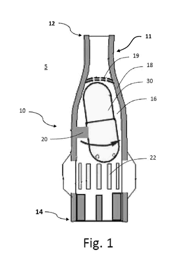
[0013] Figure 1 is cross-sectional view of a dry powder inhaler with a
protrusion
limiting capsule spin according to an exemplary embodiment of the invention.
[0014] Figure 2A is cross-sectional view of another dry powder inhaler with
a
protrusion limiting capsule spin according to an exemplary embodiment of the
invention.
Figure 2B is a perspective view of the dry powder inhaler of Fig. 2A.
[0015] Figure 3A is cross-sectional view of a dry powder inhaler with a
protrusion
limiting capsule spin according to an exemplary embodiment of the invention.
Figure 3B
is a cross-sectional view of the dry powder inhaler of Fig. 3A taken along
cross-section
[0016] Figures 4A ¨ 4C are diagrams showing airflow within an exemplary dry
powder inhaler housing having a sliding capsule mechanism according to an
exemplary
embodiment of the invention. Figure 4A shows the capsule and the airflow at
the
beginning of inhalation. Figure 4B shows the capsule and the airflow as the
capsule is
drawn proximally in response to a negative pressure within the chamber. Figure
4C
shows the aerosolized powder traveling distally through the mouthpiece.
6
CA 02982947 2017-10-16
WO 2016/168266 PCT/US2016/027240
[0017] Figures 5A is a perspective view of a dry powder inhaler with a
hinged panel
or flapper board mechanism according to an exemplary embodiment of the
invention.
Figure 5B is a cross-sectional view of the dry powder inhaler shown in Fig.
5A. Figure
5C is a magnified view of the panel in a down position and the drug chamber is
open.
Figure 5D is a magnified view of the flapper board up position and the drug
chamber is
closed.
[0018] Figure 6A is a perspective view of a dry powder inhaler with a
moving board
mechanism according to an exemplary embodiment of the invention. Figure 6B is
a
cutaway perspective view of the dry powder inhaler shown in Fig. 6A. Figure 6C
is an
alternate perspective view of the dry powder inhaler shown in Fig. 6A.
[0019] Figure 7A is a perspective view of a dry powder inhaler having a
drug powder
chamber with a check valve according to an exemplary embodiment of the
invention.
Figure 7B is a partial cutaway perspective view of the drug powder inhaler
shown in Fig.
7A. Figure 7C is an alternative perspective view of the drug powder inhaler
shown in
Fig. 7A. Figure 7D is a magnified view of the drug powder chamber housed in
the dry
powder inhaler shown in Fig. 7A.
[0020] Figure 8A is a perspective view of a dry powder inhaler with a
sliding block
mechanism according to an exemplary embodiment of the invention. Figure 8B is
a
magnified view of a check valve region shown in the dry powder inhaler of Fig.
8A.
Figure 8C is a cutaway perspective view of the dry powder shown in Fig. 8A.
Figure 8D
is an alternate perspective view of the dry powder inhaler shown in Fig. 8A.
Figure 8E
7
CA 02982947 2017-10-16
WO 2016/168266 PCT/US2016/027240
is a magnified view of the drug release opening in the dry powder inhaler
shown in Fig.
8A.
[0021] Figure 9A is a perspective view of a dry powder inhaler with dry
powder
reservoir having a pattern of small holes according to an exemplary embodiment
of the
invention. Figure 9B is an alternate perspective view of the dry powder
inhaler shown in
Fig. 9A. Figure 9C is a cutaway perspective view of the dry powder inhaler
shown in
Fig. 9A.
[0022] Figure 10A is a perspective view of a dry powder inhaler with a
sliding block
mechanism according to an exemplary embodiment of the invention. Figure 10B is
an
alternative perspective view of the dry powder inhaler shown in Fig. 10A.
Figure 10C is
a cutaway perspective view of the dry powder inhaler shown in Fig. 10A.
[0023] Figure 11A is a perspective view of a dry powder inhaler with a
moving board
mechanism according to an exemplary embodiment of the invention. Figure 11B is
an
alternate perspective view of the dry powder inhaler shown in Fig. 11A.
Figures 11C
and 11D are cutaway perspective views of the dry powder inhaler shown in Fig.
11A.
[0024] Figure 12A is a side cutaway view of a dry powder inhaler according
to an
exemplary embodiment of the invention. Figure 12B is a side view of the dry
powder
inhaler shown in Fig. 12A. Figure 12C is a perspective view of the dry powder
inhaler
shown in Fig. 12A.
DETAILED DESCRIPTION OF THE INVENTION
8
CA 02982947 2017-10-16
WO 2016/168266 PCT/US2016/027240
[0025] The present invention can be understood more readily by reference to
the
following detailed description, the examples included therein, and to the
Figures and
their following description. The drawings, which are not necessarily to scale,
depict
selected preferred embodiments and are not intended to limit the scope of the
invention.
The detailed description illustrates by way of example, not by way of
limitation, the
principles of the invention. The skilled artisan will readily appreciate that
the devices
and methods described herein are merely examples and that variations can be
made
without departing from the spirit and scope of the invention. It is also to be
understood
that the terminology used herein is for the purpose of describing particular
embodiments
only and is not intended to be limiting.
[0026] Referring now in detail to the drawings, in which like reference
numerals
indicate like parts or elements throughout the several views, in various
embodiments,
presented herein is a dry powder inhaler specifically designed for partial or
variable
dosage delivery per inhalation.
[0027] With reference to Fig. 1, a dry powder inhaler is shown according to
an
embodiment of the invention. The dry powder inhaler 10 includes a housing 18
having
a proximal end 12 and a distal end 14. The proximal end 12 of the dry powder
inhaler
features a circular opening as part of a mouthpiece component 11. The
mouthpiece
11 can either be an attachable component, or molded as a single contiguous
component with the rest of the dry powder inhaler housing 18. The housing 18
has a
series of attached walls, or is molded as one contiguous wall that defines the
outer
surface contours of the dry powder inhaler 10. The housing 18 can also define
the
geometry of an air chamber 16 within the device and the mouthpiece 11. The air
9
CA 02982947 2017-10-16
WO 2016/168266 PCT/US2016/027240
chamber 16 is in fluid communication with the mouthpiece 11, so that when a
user
inhales on the mouthpiece 11, a negative pressure or vacuum is created within
the air
chamber 16. A back stop or filter 19 has openings to permit flow of air
between the air
chamber 16 and the proximal end 12, and also prevents the capsule 30 from
clogging
the mouthpiece 11. Distal of the chamber 16 but proximal to the distal end 14
are
angled air inlets 22 that facilitate the introduction of a "turbo spin" or
"vortex" airflow
effect within the air chamber 16. If the air inlets 22 are angled in
substantially the same
direction (e.g. clockwise or counterclockwise), as the user inhales on the
mouthpiece
11, air is introduced into the air chamber 16 from the external environment 5.
Airflow
will travel from the external environment 5, through the air inlets 22, into
the air chamber
16, out of the opening at the proximal end 12 and into the user's mouth. The
decreasing cross-sectional area of the air chamber 16 in the proximal
direction
increases air pressure, leading to a burst of secondary airflow surrounding
the capsule
30 and creating a vortex-like effect. This vortex airflow causes the capsule
30 to spin
rapidly within the air chamber 16. Since the capsule is punctured, as it spins
around in
the air chamber 16, it dispenses powder into the primary airstream which is
inhaled by
the user. In certain embodiments, some of the air inlets are angled in one
direction,
while other are neutral and/or or angled in the opposite direction, for
limiting the spin of
the capsule during a single inhalation.
[0028] As illustrated in Fig. 1, the capsule 30 sits within the air chamber
16 at an
angle. The angled stance of the capsule 30 is created by a protrusion 20 which
is an
internal component of the housing 18 that protrudes into the air chamber 16
cavity. As
the vortex airflow acts to spin the capsule 30, the protrusion 20 has a
limiting effect,
CA 02982947 2017-10-16
WO 2016/168266 PCT/US2016/027240
limiting the duration of the spin by skewing the capsule 30 at an angle,
slightly
misaligned with the axis of the vortex and the longitudinal axis of the dry
powder inhaler
10. In addition, the protrusion has a limiting effect by further interfering
with the overall
space that the capsule 30 has within the air chamber 16 to spin freely. Both
of these
limiting effects act to minimize and stop the spinning of the capsule 30,
resulting in a
partial dosage of powder dispensed during a single inhalation. The chase air
provided
by the air inlets 22 provides a smooth and full inhalation for the user by
introducing air
into the mouthpiece 11 from the external environment 5, even though air
movement
through the chamber 16 is restricted. Thus, dispensation of a full dosage of
powder
from the capsule requires multiple inhalations by the user. Shapes of
protrusions
disclosed herein are not limited to rectangular. Protrusion shapes may be any
number
of geometries, including but not limited to rounded, triangular, curved,
straight, or any
combination of these. Leaf springs, ribbed chambers, and non-circular
chambers, such
as a heart shaped or other concave and concave shaped chamber, can also be
utilized
to limit movement of the capsule. Further, more than one protrusion can be
present,
and multiple protrusions can have different shapes and heights. Multiple
protrusions do
not have to be spaced equidistant from each other. In certain embodiments, the
protrusion is disposed within the device so that the capsule is likely to stop
with the
punctured portion of the capsule facing the mouthpiece. In other embodiments,
the
protrusion is disposed within the device so that the capsule is likely to stop
with the
punctured portion either perpendicular or facing away from the mouthpiece.
Placement
and design considerations of the protrusions can be based on the structure of
the dry
powder inhaler and the desired dosage of each inhalation.
11
CA 02982947 2017-10-16
WO 2016/168266 PCT/US2016/027240
[0029] Alternative embodiments of a dry powder inhaler with a protrusion
for limiting
capsule spin and administering a partial dosage of powder are shown in Figs.
2A and
2B. With reference to the alternative embodiment shown in Fig. 2A, the dry
powder
inhaler 40 has a proximal end 42, a distal end 44, and a housing 48 defining a
chamber
46 for the receipt of a dry powder capsule 30. Mouth guards 47, 49 are
positioned on
external surfaces of the dry powder inhaler 40 to allow for a better fit with
the user's
mouth during inhalation. One or more air inlets 52 are disposed adjacent to
the
mouthpiece 54 and the chamber 46. The air inlets 52 are positioned and angled
for
bringing air into the chamber 46 and mouthpiece 54 from the external
environment 5,
creating a circular airflow within the chamber 46 for spinning the capsule 30.
As the
punctured capsule 30 spins in the chamber 46, powder is dispensed in a primary
airflow
directed distally through the mouthpiece 54, entering the user's mouth during
inhalation.
A protrusion 50 is connected to or molded from the housing 48, and protrudes
out into
the cavity of the chamber 46. Without the protrusion 50, an unrestricted
chamber may
otherwise spin the capsule 30 such that the entire dosage of medicament is
dispensed
in a single inhalation. The protrusion 50 is configured to restrict the spin
of the capsule
30 so that a single inhalation by the user yields only a partial dose of
powder into the
primary airflow. Not only does the protrusion 50 physically restrict movement
of the
capsule 30, it also interrupts the aerodynamic of the vortex, yielding a
restricted
movement of air within the chamber 46.
[0030] Another alternative embodiment of a dry powder inhaler with a
protrusion is
shown in Figs. 3A and 3B. The dry powder inhaler 60 has a housing 68 extending
from
a proximal end 62 to a distal end 64. The housing 68 defines the chamber 66
where the
12
CA 02982947 2017-10-16
WO 2016/168266 PCT/US2016/027240
capsule 30 resides. The proximal end 62 of the inhaler 60 has a mouthpiece 74
for
interface with the user's mouth. Air inlets 72 are disposed around the edges
of the
chamber 66 and penetrate the housing 68 at an angle so that as the user
inhales on the
mouthpiece 74, air is drawn from the external environment 5 to create a
vortical airflow
within the chamber 66. The vortical airflow spins the capsule 30 within the
chamber 66,
however, the protrusion 70 limits the duration of spin by limiting the space
and range
that the capsule is allowed to spin unrestricted. The protrusion 70 also
interferes with
the airflow dynamics within the chamber 66 so that a less than optimal vortex
is created
as the stream of air is partially blocked by the protrusion 70.
[0031] In certain embodiments, powder from the pierced capsule is dispensed
into
the mouthpiece through a sliding motion of the capsule, rather than a spinning
motion of
the capsule. With reference to Figs. 4A ¨ 4C, a dry powder inhaler 80 has a
housing 88
extending between a distal end 84 and a proximal end 82 of the device, with a
mouthpiece 81 situated at the proximal end 82 for user inhalation. As shown in
Fig. 4A,
as the user inhales on the mouthpiece 81, a negative pressure builds up
internally
within the housing 88, moving air through the chamber 86 and the mouthpiece 81
in a
proximal direction. As the negative pressure within the housing 88 rapidly
builds, the
capsule 30 starts to slide and accelerate in the proximal direction with the
direction of
flow of air. Protrusions 90 extending into interior cavities of the housing 88
create a
portion of the chamber 86 that is less than the diameter of the proximally
punctured
capsule 30. As illustrated in Fig. 4B, the protrusions 90 stop the proximal
sliding
movement of the capsule 30. This interface creates a check valve as the
capsule 30
strikes the protrusions 90 on the distal end of the chamber 86 for initiating
a partial
13
CA 02982947 2017-10-16
WO 2016/168266 PCT/US2016/027240
dosage ejection of powder my means of an inertial release. As in previous
embodiments and as shown in Fig. 4C, a continued chase flow of chase air flows
through air inlets 92 continue even after the chamber 86 is plugged by the
capsule 30,
and the capsule 30 has stopped moving within the chamber 86 during the
inertial
release of powder. The chase air flow helps to aerosolize the powder, while
providing
the user with a smooth and full finish to their inhalation. In certain
embodiments, the air
inlets 92 are angled so that a vortical airflow is introduced into the
cavities of the
housing.
[0032] Dry powder inhalers according to this and other embodiments
disclosed
herein can be manufactured with advantages that cause users to mimic maneuvers
associated with smoking a conventional cigarette. For instance, in the
embodiment
shown in Figs. 4A ¨ 4C, as the user inhales, the capsule is rapidly
accelerated
proximally into the tapered protrusion geometry of the distal portion of the
chamber. If
the angle of the taper is shallow enough, the capsule can become temporarily
stuck and
lodged between tapered walls so that the user has to tap or jolt the inhaler
in order to
reset the capsule to the distal end of the inhaler. This action may be
preferential for
some users who desire to mimic the traditional maneuver of "flicking off the
ashes" on a
conventional cigarette. As a conventional cigarette burns, the part that has
already
been smoked remains at the distal tip in the form of a fine gray ash. Often,
the ash will
not fall from the cigarette unless a flicking motion (e.g. tapping and end of
the cigarette
with one or more fingers) is executed to jolt the ash loose. Thus, designs
that manage
to sandwich the sliding capsule within the tapered region, requiring a jolt to
loosen it
again, may incorporate maneuvers that coincide with smoking a traditional
cigarette. In
14
CA 02982947 2017-10-16
WO 2016/168266 PCT/US2016/027240
addition, "stubbing out" a cigarette, which is essentially a maneuver for
grinding the end
of a cigarette against a surface for safe disposal after you are finished with
it, is another
maneuver that could be mimicked for jolting the capsule loose.
[0033] Now with reference to Figs. 5A ¨ 5D, embodiments of the invention
utilize a
swinging flapper board for providing a partial dosage per inhalation. The dry
powder
inhaler 100 has a housing 114 extending between a proximal 102 end and a
distal end
104. The exterior profile of the housing 114 is substantially cylindrical,
with circular
openings at either end of the inhaler 100. A portion of the housing 114
further defines
an upper chamber serving as the drug powder chamber 106, and a lower chamber
serving as an air chamber 108, both within the housing 114. The drug powder
chamber
106 is designed to contain the dry powder medicament, while the lower air
chamber 108
is designed to provide an airflow pathway between the user's mouth, the drug
powder
chamber 106 and the external environment 5. The two chambers 106, 108 overlap
in a
mid-section of the inhaler 100. A flapper board 110 is connected to internal
portions of
the housing 114 using a hinged connection. As shown with more detail in the
magnified
views of Figs. 5C and 5D, the flapper board 110 is shaped to both swing freely
within
the cavity of the housing 114, and to cover the proximal opening of the drug
powder
chamber 106 when swung upright. With reference back to Figs. 5A and 5B, the
distal
end of the housing 114 features a check valve 112, opening when a threshold
pressure
is reached within the air chamber 108. The flapper board 110 can be made of
any
suitable material known in the art, including elastomers such as silicone and
certain
medical grade plastics, and is substantially semicircular or D-shaped. The
check valve
112 can be made of materials known in the art such as elastomeric silicone. In
this
CA 02982947 2017-10-16
WO 2016/168266 PCT/US2016/027240
embodiment and in other embodiments described herein, the check valve 112 is
dome
shaped with a plurality of intersecting slits that upon responsive to a
threshold pressure.
In alternative embodiments, the check valve can be a disc valve, a duckbill
valve, or
other valve configurations known in the art. Elastomeric check valves can have
one slit,
or a plurality of intersecting or nonintersecting slits.
[0034] As shown in Figs. 5A ¨ 5D, the flapper board 110 is near the opening
at the
proximal end 102 of the inhaler 100 and the check valve 112 is at the opposite
distal
end 104 of the inhaler 100. As the user starts to inhale on the proximal end
102 and
create a negative pressure within the housing 114, they will inhale a small
amount of
powder from the drug powder chamber 106. As shown with more detail in Fig. 5C,
the
flapper board 110 is initially down just as the user begins to inhale. As the
user's inhale
reaches a certain threshold pressure level, the check valve 112 will open
responsive to
reaching the threshold, causing the flapper board to flip upright as air from
the external
environment 5 is introduced into the air chamber 108. As shown with more
detail in Fig.
5D, the flapper board 110 closes the drug chamber 106 when in the upright
position. As
a result, chase air from the external environment 5 enters the primary air
stream via the
air chamber 108, and the user can complete their inhale. During a single
inhalation, the
user has picked-up only a partial amount of the powder stored in the drug
powder
chamber 106.
[0035] An alternative embodiment for providing a user with a partial dosage
of
powder in a single inhalation is shown in the dry powder inhaler of Figs. 6A ¨
6C. The
dry powder inhaler 120 has a proximal end 122, a distal end 124 and a cylinder
shaped
housing 134 extending therebetween. A portion of the housing 134 forms a thin
straw
16
CA 02982947 2017-10-16
WO 2016/168266 PCT/US2016/027240
128 running longitudinally through the center of the inhaler 120. Coaxially
surrounding
the thin straw 128 is the drug powder chamber 126 for storing powder
medicament. Air
inlets 132 are positioned in fluid communication with the drug powder chamber
126 for
allowing the inflow of air from the external environment 5 into cavities of
the housing
134. A moving board 130 is positioned within the distal end 124 of the housing
134.
The moving board 130 is essentially a circular disk having a diameter slightly
smaller
than the diameter of the housing 134 cavity at the distal end 124. The moving
board
130 has a thickness or height that keeps the disk shaped element flush against
internal
housing 134 walls so that it does not flip or twist. As shown in Fig. 6C, the
moving
board 130 can slide proximally or distally along the longitudinal axis of the
inhaler 120.
A lip structure of the distal end 124 of the housing 134 prevents the moving
board 130
from sliding distally out of the housing 134.
[0036] During operation, a user generates a negative pressure at the
proximal end
122 of the inhaler 120 during inhalation. The moving board 130, which is
normally free
to slide back and forth at the distal end 124 of the inhaler 120, will
accelerate proximally
with the direction of airflow and eventually interface with distal end 124
openings of the
drug powder chamber 126 and the thin straw 128. Since the moving board 130 is
sized
to fill the diameter of the cavity at the distal end 124 of the housing 134,
the board 130
effectively plugs the air pathways of the drug powder chamber 126 and the thin
straw
128. Nonetheless, the user can continue to inhale a partial dose of powder
since a
small amount of powder has been introduced into the primary airflow and the
thin straw
128 prior to the plugging of the air pathways by the moving board 130. As the
inhalation
pressure enters a peak, the powder is aerosolized, and subsequently enters the
user's
17
CA 02982947 2017-10-16
WO 2016/168266 PCT/US2016/027240
upper respiratory tract and lungs. As the user completes the inhalation, the
moving
board becomes loose again and a small amount of powder will again fall into
the thin
straw 128, ready for the next inhalation. Normally, gravity and inhalation
forces will be
adequate for knocking small amounts of powder into the primary airflow and the
thin
straw. Maneuvers such as "flicking off the ashes" or "stubbing out" as
described above
can also be used to knock small amounts of powder into the thin straw between
inhalations.
[0037] Now with reference to Figs. 7A ¨ 7D, an alternate embodiment of a
dry
powder inhaler having a small check valve on the dry powder chamber and a
second
check valve running across the air chamber is shown. The dry powder inhaler
140 has
a proximal end 142, a distal end 144 and a housing 154 extending therebetween.
The
outer surface of the housing 154 has a substantially cylindrical shape. The
user inhales
through the proximal end 142 of the inhaler, generating a negative pressure
within the
air chamber 146. The air chamber 146 is adjacent the drug powder chamber 148,
which serves as reservoir for storing a bulk amount of powder medicament. A
small
check valve 150 seals an opening in the drug powder chamber 148, so that
powder
cannot pass into the air chamber 146 unless the small check valve 150 actuates
open.
The small check valve 150 can be an elastomeric pressure actuated valve known
in the
art or described herein, such as a silicone slit valve. The small check valve
150 is
configured to actuate open in response to a negative pressure within the air
chamber
146. The air chamber 146 extends from the distal end 144 opening of the
housing 154
to the proximal end 142 opening. A larger check valve 152 lies across the
distal end
144 opening of the housing, and is configured to actuate in response to a
second
18
CA 02982947 2017-10-16
WO 2016/168266 PCT/US2016/027240
threshold pressure. The second threshold pressure required to actuate the
larger check
valve 152 is greater than the first threshold pressure required to actuate the
smaller
check valve 150.
[0038] As the user starts to inhale on the proximal end 142 opening of the
inhaler
140, a negative pressure is generated in the air chamber 146. Since the
threshold
resistance of the small check valve 150 is less than the threshold resistance
of the
larger check valve 152, the small check valve 150 will open first as negative
pressure
builds, and a partial amount of drug powder will fall into the air chamber for
the user to
inhale. As negative pressure within the air chamber 146 becomes higher, the
larger
check valve 152 will open, which substantially reduces the negative pressure
in air
chamber 146 and causes the small check valve 150 to close to keep more drug
powder
from falling. Dry powder inhalers 140 according to this design can dispense a
partial
dose of powder over a single inhale, while allowing for a smooth inhalation of
chase air
for comfortably sending the aerosolized powder into the upper respiratory
tract and into
the lungs.
[0039] Certain embodiments of the invention use a spring mechanism for
dispensing
a partial amount of powder into the inhalation primary airflow, as shown in
Figs. 8A ¨
8E. The dry powder inhaler 160 has a proximal end 162 and a distal end 164
with a
housing 174 extending therebetween. The housing 174 holds an air chamber 166
and
a drug powder chamber 168 (see Figs. 8C and 8E) for holding dry powder such as
nicotine powder. A first check valve 170 is fixed to the proximal end 162 of
the drug
powder chamber 168 and a block 179 is fixed to the distal end 162 of the drug
powder
chamber 168. A second check valve 172 is fixed to the distal end of the air
chamber
19
CA 02982947 2017-10-16
WO 2016/168266 PCT/US2016/027240
166. As shown in Fig. 8B, the first check valve 170 has three slits that meet
at the
center of the elastomeric valve member. With reference to Fig. 8C, a spring
178
wrapped around a column 177 applies a small compression force to the block
179,
biasing the block 179 towards the distal end 164 of the housing 174. If the
block 179 is
moved in a proximal direction, the first check valve 170 slits will crack the
valve open.
As shown in the magnified view of Fig. 8E, a small hole 176 centered at the
proximal
end of the drug powder chamber 168 is also aligned with the center of the
first check
valve 170. This small hole 176 is configured to dispense partial dosages of
powder as
the block 179 moves proximally, shifting powder proximally and pushing it
through the
small hole 176 and the slits in the first check valve 170. As the user begins
to inhale
from the proximal end 162 of the air chamber 166, a negative pressure begins
to build
in cavities of the air chamber 166. This pressure extends from the proximal
end 162
opening to the second check valve 172 at the distal end 164 of the housing
174. When
the negative pressure reaches a threshold level, the second check valve 172
will open,
allowing additional air to enter the air chamber from the external environment
5.
Incoming air moving proximally through the housing 174 will push the block 179
against
the spring 178 column 177, shifting powder proximally and pushing a partial
dosage of
powder through the small hole 176 as the first check valve 170 cracks open.
The
primary airflow aerosolizes the powder for inhalation by the user. The
remaining
powder is secured within the reservoir until the next inhalation by the user.
[0040] Another exemplary embodiment of the invention utilized a dry powder
reservoir having a grid of tiny openings for dispensing powder into an air
chamber, as
shown in Figs. 9A ¨ 9C. The dry powder inhaler 180 has a housing 196 extending
CA 02982947 2017-10-16
WO 2016/168266 PCT/US2016/027240
between a proximal 182 and distal 184 end. The interior of the housing 196
includes an
air chamber 186 extending the length of the inhaler 180. The distal end 184 of
the air
chamber 186 is capped, while the proximal end 182 of the air chamber 196 is
open. A
hole 192 in the side of the housing 196 equalizes the pressure in the air
chamber 186
with the atmospheric pressure of the external environment 5. The interior also
houses a
cylindrical dry powder chamber 188 featuring a pattern of holes 194 that are
in fluid
communication with the air chamber 186, shown with detail in Fig. 9C. The
holes 194
permit very small amounts of powder to pass through to the air chamber 186. In
certain
embodiments, the holes 194 are slightly larger than the size of a single
powder particle.
In other embodiments, the holes 194 range in diameters of 2-5 times the size
of a single
powder particle. The hole 194 diameters can vary in size, and in certain
embodiments,
gradually change diameters moving in a proximal direction. The distal end of
the dry
powder chamber 188 features a pressure actuated check valve 190. When the user
initiates inhalation on the proximal end 182 of the housing 196, negative
pressure is
generated within the air chamber 186. The airflow generated by the negative
pressure
causes powder to squeeze through the holes 194 in the dry powder chamber 188.
Transfer of the dry powder from the dry powder chamber 188 to the air chamber
186 is
facilitated by the check valve 190 that opens in response to a threshold
pressure. The
check valve 190 permits an inside-out airflow inside the dry powder chamber
188,
pulling air in from the air chamber 186 and forcing powder back out into the
primary
airflow of the air chamber 186. Partial dosages of powder aerosolize in the
primary
airflow for inhalation by the user. The hole 192 in the side of the housing
196 connects
21
CA 02982947 2017-10-16
WO 2016/168266 PCT/US2016/027240
the air chamber 186 to the atmosphere 5 so that it will balance the pressure
slowly to
stop the drug powder from falling down all the time.
[0041] Another embodiment of a dry powder inhaler utilizing a spring and a
moving
block is shown in the dry powder inhaler of Figs. 10A ¨ 10C. The dry powder
inhaler
200 has a cylindrical housing 218 extending from a proximal end 202 to a
distal end
204. The distal end 204 of the housing 218 includes an air chamber 206 in
fluid
communication with the opening on the proximal end 202 of the housing 218, and
two
opposing D-shaped chambers. The top D-shaped chamber is the dry powder chamber
208, which stores bulk amounts of powder medicament. The proximal and distal
ends
of the dry powder chamber 208 are capped, and the bottom floor of the dry
powder
chamber has a small opening 214 that allows powder small amounts of powder to
fall
from the dry powder chamber 208 into the air chamber 206. In certain
embodiments,
the small opening 214 is sealed by a check valve that opens in response to a
negative
pressure within the air chamber initiated by the start of user inhalation. The
bottom
chamber is the external air chamber 210, which is capped at its proximal end
and open
at its distal end in fluid communication with the external environment 5. As
shown in
Fig. 10C, the top of the external air chamber has an air opening 213 to allow
air into the
air chamber 206. In alternative embodiments, the air opening 213 is in the
proximal cap
of the external air chamber, optionally sealed with a check valve to open for
chase air
as the user inhaled powder medicament. With reference now to Figs. 10B and
10C, a
spring 216 is attached to the back of a block 212 that slides along the bottom
surface of
the dry powder chamber 208 and the top surface of the external air chamber
210. The
block is biased towards a distal end of the air chamber 206 by the spring 216,
which is
22
CA 02982947 2017-10-16
WO 2016/168266 PCT/US2016/027240
connected to a capped distal end of the air chamber 206. During operation, the
user
inhales through the proximal end opening of the housing 218, generating a
negative
pressure within the air chamber 206. Since the block 212 starts off in a
relaxed state at
the distal end of the air chamber 206, biased distally by the spring 216, the
opening 214
to the dry powder chamber 208 is uncovered, and a small amount of powder is
present
in the air chamber 206. As the user ramps up their inhale, air from the
external
environment 5 is introduced into the external air chamber 210 and drawn into
the main
air chamber 206 through the air opening 213. This creates a proximally
directed
primary airflow towards the user's mouth. The negative pressure will
eventually reach a
threshold which slides the block 212 far enough proximally so that the block
212 covers
the small opening 214 in the dry powder chamber 208, ensuring that no more dry
powder leaves the dry powder chamber 208 during that inhalation. As the user
approaches the peak of their inhalation, the primary airflow aerosolizes the
powder
present in the air chamber 206 so that it enters the upper respiratory tract
and lungs of
the user. As the user winds down their inhalation, the block 212 slides back
distally
towards its original biased position, and a small amount of powder drops back
into the
air chamber 206, ready for next inhalation.
[0042] A moving board embodiment of a dry powder inhaler is shown in Figs.
11A ¨
11D. The dry powder inhaler 220 has an air chamber 226 extending between a
proximal end 222 and a distal end 224 of the device. The dry powder chamber
228
stores bulk powder medicament and has a moving board 236 at its distal end and
a
flipping board 230 at its proximal end, separated by a spring 234. Holes 212
provide
fluid communication between the dry powder chamber and the external
environment
23
CA 02982947 2017-10-16
WO 2016/168266 PCT/US2016/027240
atmosphere 5. When the user starts to inhale, a negative pressure is generated
in the
air chamber 226, which starts to squeeze powder from the dry powder chamber
228.
The flipping board 230 can flip back and forward. When in the convex-out
position
shown in Figs. 11C and 11 D, the flipping board 230 clamps the bar 239 with
the spring
234 to keep it from moving. The flipping board 230 squeezes out a partial
dosage of
powder while the patient is inhaling. After the inhalation is complete, the
flipping board
becomes loose again, and releases its clamp.
[0043] In certain embodiments, a shaped component is rotated to deliver
partial
dosages of a powder to the air chamber. As shown in Figs. 12A ¨ 12C, a housing
260
of the inhaler 240 has a circular component to its shape for housing a wheel
256 and a
drug chamber 248. An air chamber 248 runs through portions of the housing 260,
terminating in an opening at the proximal end 242 of the housing 260. The
wheel 256
has a wheel opening 252 providing fluid communication between rotating
transfer
chambers 250 and the drug chamber 248. The wheel 256 and portions of the
housing
260 are made of a semi-flexible material, such as plastic or a semi-rigid
shape memory
polymer. In this embodiment, a pentagon shaped component 246 is designed to
fit and
rotate within the wheel 256. Protrusions 262 on the inside of the wheel 256
interface
with the geometry of the pentagon shaped component 246 so that in an
uncompressed
state, the protrusions 262 oppose corners of the pentagon shaped component 246
and
restrict it from continuing to rotate past its current position. Since
portions of the
housing 260 and wheel 256 are semi-flexible, users can squeeze the housing 260
and
wheel 256 by pressing two or more contact points 258 towards each other.
Squeezing
the contact points 258 temporarily distorts the shape of the wheel 256 so that
the
24
CA 02982947 2017-10-16
WO 2016/168266 PCT/US2016/027240
protrusions 262 allow the wheel 256 to slip by and spin counterclockwise to
the next
position. In certain embodiments, the interface between wheel protrusions 262
and
corners of the pentagon shaped component 246 can generate an audible "click"
as the
corner slips past the protrusion, indicating to the user that a new transfer
chamber 250
is in position at the wheel airway opening 254. In the embodiment illustrated,
each flat
edge of the pentagon shaped component 246 and corresponding curved edge of the
wheel 256 between protrusions 262 defines the geometry of a transfer chamber
250.
During operation, a user will inhale on the opening at the proximal end 242 of
the
housing 260, generating a negative pressure within the air chamber 248. When
the
inhaler 240 is being used for the first time, one or more transfer chambers
250 can be
preloaded with a partial dose of powder. If, for example, the user receives an
inhaler
where only the transfer chamber adjacent to the wheel opening 252 contains
powder,
the user may be instructed to turn the pentagon shaped component 246 four
"clicks"
counterclockwise to put the powder in position to transfer through the wheel
airway
opening 254. With the powder positioned behind the wheel airway opening 254,
the
user can inhale through the opening at the proximal end 242 of the housing
260,
inhaling the partial dose of powder medicament. Subsequent inhalations of
subsequent
partial dosages of powder can be taken by squeezing the housing 260 at the
contact
points 258, turning the pentagon shaped component 246 counterclockwise one
click,
and inhaling through the air chamber 248. In alternate embodiments, the
pentagon
shaped component 246 is another shape, such as a square, triangle, hexagon,
heptagon, octagon or other regular polygon-like shape and the wheel 256 can be
modified accordingly as will be appreciated by those having ordinary skill in
the art.
CA 02982947 2017-10-16
WO 2016/168266 PCT/US2016/027240
[0044] Designs according to embodiments of the invention can be modified to
approximate flow resistance and volume flow rate models determined to be
comfortable
to users. Valves, air inlets, chamber dimensions, mouthpiece pathways, housing
dimensions, and limiting components can be designed so that the user initially
pulls for
about one second, similar to drag on a cigarette. Partial dosages are
fluidized and
deagglomerated, and enter the mouth and the upper respiratory tract of the
user. After
about one second, chase air can be delivered at a much lower flow resistance
and is
utilized as a primary source of air introduced into the system. The higher
flow rate takes
aerosol comfortably beyond the upper respiratory tract to the lungs.
[0045] The disclosures of each and every patent, patent application, and
publication
cited herein are hereby incorporated herein by reference in their entirety.
While this
invention has been disclosed with reference to specific embodiments, it is
apparent that
other embodiments and variations of this invention may be devised by others
skilled in
the art without departing from the true spirit and scope of the invention. The
appended
claims are intended to be construed to include all such embodiments and
equivalent
variations.
26