Note: Descriptions are shown in the official language in which they were submitted.
CA 02983278 2017-10-18
WO 2016/172605 PCT/US2016/029011
METHOD AND SYSTEM FOR POWER EXCHANGE
CROSS REFERENCE TO RELATED APPLICATIONS
[0001] This application claims benefit of U.S. Provisional Application No.
62/150,937, filed
April 22, 2015 and U.S. Provisional Patent Application No. 62/166,339, filed
May 26, 2015,
both herein incorporated by reference.
FIELD OF INVENTION
[0002] The present invention relates to a method and system for exchanging a
power source
which includes but is not limited to replacing, i.e. exchanging, one power
supply such as a
battery for another. Advantageously, this includes the exchange of the power
source of an
electric vehicle.
BACKGROUND OF THE INVENTION
[00031 Alternative fuel vehicles are becoming increasingly popular. Such
vehicles use
alternative fuel sources than conventional petroleum such as gasoline and
diesel. Some
alternative fuel sources include but are not limited to natural gas,
battery/chemical-electrical
source, fuel cell, etc. As with conventional vehicles, one must replenish the
fuel source
consumed by the vehicle. This has resulted in the development of various
refueling, recharging,
regeneration or other means for replenishing the fuel source for the
alternative fueled vehicle.
[0004] Alternative fuel vehicles which are powered by battery in many
instances are
recharged by plugging the vehicle into a suitable recharging receptacle which
recharges the
batteries on-board the vehicle. One recent alternative to this is to replace
the battery packs on the
1
CA 02983278 2017-10-18
WO 2016/172605 PCT/IJS2016/029011
vehicle after they have been depleted with fully charged batteries. However,
current
technologies for accomplishing alternative powered vehicle battery
replacements in the field
requires significant infrastructure in terms of a facility to accommodate the
vehicle during a
battery exchange and the mechanism necessary to accomplish a replacement of a
series of
depleted batteries with replacement ones that are charged. Accordingly, such
systems are not
economically feasible and/or developed at a stage which allow for real-time
battery replacement
as a means of replenishing an alternative powered vehicle every time its
battery is depleted.
SUMMARY OF THE INVENTION
[0005] The present technology, hereafter known as Autonomous Linear Exchange
(ALE)
includes a unique method and system for removing, receiving, charging,
deploying, and
replacing a vehicle's main power source, include a power sourse disposed in
container, in which
the container includes a power source such as a battery bank, fuel cell, or
other stored power
device, of an Auxiliary Powered Exchange equipped vehicle. This includes
devices which
operate by electricity, e.g. using a battery as well as those which utilize a
fuel cell More
specifically this technology can be used to exchange the main drive batteries
of an electric
powered vehicle which are disposed in a container or other replaceable unit.
However, this
technology can be adapted for use for exchanging any power source including
various types of
power sources which are used by vehicles including electric vehicles. The
present invention
pertains to both stationary equipment designed to receive, charge, organize,
and deploy said
power sources, batteries or fuel cells with extreme efficiency and simplicity,
as well as
componentry and a specialized modular container intended for incorporation
into automotive
designs which enable the vehicle to interact with the stationary equipment.
2
CA 02983278 2017-10-18
WO 2016/172605 PCT/US2016/029011
[0006] In one advantageous form, a suitable vehicle has a battery bank,
battery pack, power
pack, cell(s), including fuel cells, etc., (collectively generically referred
to as a "power cell"
which may include one or more cells or discrete power units) self-contained in
what is referred to
in this disclosure as a "container". This container also includes, in an
advantageous
embodiment, an oil cooler and the container may also include other elements
which allow the
container to be a self-contained, removable power source, which provide main
power to the
vehicle. It is this container which is exchanged when depleted of power using
the present
system.
[0007] Further, in addition to the container which is the main power source
for the vehicle,
the vehicle will advantageously also have auxiliary power which assists during
the container
exchange. Preferably, both the power cell (in the container) and the auxiliary
power can be
recharged (as an option if desired by the manufacturer) by plugging the
vehicle into a suitable
recharging outlet/source.
[0008] In yet another advantageous form, power may be supplied during the
lifting of a
replacement container into the vehicle using the power in the power cell of
the container. Thus
the power cell in the replacement container will augment and/or supplant the
use of the vehicle's
auxiliary power source
[0009] The present invention, in one form thereof, relates to a system for
vehicle power
exchange. The system has at least one power exchange strip and at least one
charged container
having a power cell and being associated with the at least one power exchange
strip. A wireless
communication device is operatively associated with the at least one power
exchange strip for
communicating between the at least one power exchange strip and a vehicle
requesting power
3
CA 02983278 2017-10-18
WO 2016/172605 PCT/US2016/029011
exchange. A processor is associated with the at least one power exchange strip
and the wireless
communication device for controlling functions of the vehicle requesting power
exchange.
100101 In one further form, the at least one power exchange strip has a first
station for
receiving a depleted container with power cell from a vehicle requesting power
exchange and a
second station has a replacement container with charged power cell for
installation of the
container into the vehicle after the depleted container has been removed. In
one further
advantageous form, the processor controls movement of the vehicle between the
first station and
the second station.
100111 In an alternative further form, the vehicle has auxiliary power in
addition to the power
in the container's power cell to be replaced, which auxiliary power, powers
movement of the
vehicle from the first station to the second station, after the depleted power
pack has been
removed from the vehicle.
[00121 In alternative forms, depending on the vehicle, the power cell is a
chemical battery
pack or a fuel cell pack.
[00131 The present invention, in another form thereof, relates to an on-board
vehicle system
for power exchange. The on-board vehicle system has a removable container with
a power cell
for primarily powering movement of the vehicle. A computer processor is
associated with the
vehicle for controlling requisite functions of the vehicle during power
exchange including
releasing a depleted container, movement of the vehicle after the depleted
power pack has been
removed and insertion of a replacement container with charged power cell into
the vehicle. A
drop mechanism is associated with the computer processor for releasing a
depleted container. A
4
CA 02983278 2017-10-18
WO 2016/172605 PCT/US2016/029011
lift mechanism is operatively associated with the computer processor for
inserting a replacement
container with charged power cell into the vehicle.
[0014] In one further form, an auxiliary power source is provided in the
vehicle to power the
drop mechanism and the lift mechanism. In one further form, the auxiliary
power also powers
movement of the vehicle from a first charging station after the removable
container with depleted
power cell has been removed from the vehicle, to a second station where a
replacement container
with charged power cell is located.
[0015] The present invention, in another form thereof, relates to a method for
vehicle power
exchange. The method includes receiving a vehicle for power exchange at a
first position along
a power exchange strip and establishing a wireless communication connection
between the
vehicle and the power exchange strip to control vehicle function during power
exchange. The
method further includes communicating instructions to a computer processor of
the vehicle via
the wireless communication connection to release a container with depleted
power cell from the
vehicle at the first position along the power strip The vehicle is then moved
to a second position
along the power exchange strip. Finally, a replacement container with charged
power cell is
inserted into the vehicle, in which the replacement container is associated at
the second position
of the power exchange strip. The method in a further form includes moving the
vehicle to a
second position along the power exchange strip, using auxiliary power on-board
the vehicle,
supplemental to the power of the removed power cell.
100161 In one further form, communicating instruction to a computer processor
of the vehicle
via the communication connection releases a depleted container from the
vehicle, at the first
position along the power exchange strip resulting in the vehicle releasing the
depleted container.
CA 02983278 2017-10-18
WO 2016/172605 PCT/US2016/029011
[0017] The present method in a further form includes inserting a container
with charged
power cell, associated with the second position of the power strip, into the
vehicle by engaging
the charge container using a lift mechanism. In one further advantageous form,
the lift
mechanism is on-board the vehicle.
[0018] In use, a compatible vehicle approaches an entrance to the charge-
strip, at a
predetermined range, the vehicle will automatically come to a stop and normal
driving control
will be suspended. At this point wireless communication from the charge strip
will provide
instructions to the vehicle's on-board computer concerning which terminals
along the charge
strip to stop over and interact with. Once instructions are received, the
vehicle's autonomous
control system engages and drives the vehicle to a precise position over the
instructed empty
charge terminal requiring no human interaction. The vehicle then switches to
its on-board
auxiliary power source, releases chassis locks and uses an on-board mechanism
to lower its
container with depleted power cell onto the empty terminal. Then, after
releasing the container,
the vehicle retracts the on-board mechanism in order to once again pass over
the strip and row of
banks. The vehicle then moves under auxiliary power, and is guided by wireless
and optical cues
from the charge strip via autonomy to the most-charged container designated by
the provided
instructions. It then uses auxiliary power to lower the on-board mechanism
once again and lock
into the replacement container with charged power cell lying on the charge-
strip. Then the
on-board mechanism lifts the container into the vehicle's chassis and locks
secure it in place.
The vehicle then switches back to main power and proceeds under autonomous
control to the
exit of the charge strip. As the vehicle passes over the very end of the strip
it comes to a stop
automatically, suspends autonomous control, and reinstates normal control. The
vehicle is then
able to proceed from the charge trip under normal control with a charged power
cell in the
6
CA 02983278 2017-10-18
WO 2016/172605 PCT/US2016/029011
container of the vehicle, while leaving the container with depleted power cell
on the strip for
charging.
BRIEF DESCRIPTION OF THE DRAWINGS
[0019] Preferred embodiments of the present invention will now be described,
by way of
example, with reference to the accompanying drawings, in which:
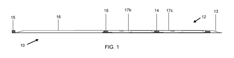
[0020] Figure 1 is a side elevation view of an Autonomous Linear Exchange
(ALE)
charge-strip with two containers lying on the strip in accordance with the
present invention.
[0021] Figure 2 is a top plan view of the Autonomous Linear Exchange charge-
strip and two
containers shown in Figure 1.
[0022] Figure 3 is a side elevation view of the Autonomous Linear Exchange
system of
Figure 1 shown with a vehicle in position to perform an ALE power exchange in
accordance
with the present invention.
[0023] Figure 4 is a top plan view of the Autonomous Linear Exchange system
and vehicle
shown in Figure 3.
[0024] Figure 5 is a side elevation view of an Autonomous Linear Exchange
equipped
vehicle in accordance with the present invention.
[0025] Figure 6 is a top plan view of the Autonomous Linear Exchange equipped
vehicle of
Figure 5.
7
CA 02983278 2017-10-18
WO 2016/172605 PCT/US2016/029011
[0026] Figure 7 is a side elevation view of an Autonomous Linear Exchange
Series 1
equipped vehicle in accordance with the present invention.
[0027] Figure 8 is a side elevation view of an Autonomous Linear Exchange
Series 2
equipped vehicle shown in accordance with the present invention.
[0028] Figure 9 is an expanded side elevation view of an isolated Autonomous
Linear
Exchange Series 2 lift mechanism and an isolated ALE container in accordance
with the present
invention.
[0029] Figure 10 is an expanded top plan view of the Autonomous Linear
Exchange Series 2
lift mechanism and container taken along line 10-10 in Figure 9.
100301 Figure 11 is a detailed side elevation view of an Autonomous Linear
Exchange
Series 2 equipped vehicle in accordance with the present invention.
[0031] Figure 12 is a detailed top plan view of the Autonomous Linear Exchange
Series 2
equipped vehicle taken along line 12-12 in Figure 11.
[0032] Figure 13 is a side elevation view of an Autonomous Linear Exchange
container in
accordance with the present invention.
[0033] Figure 14 is a top plan view of the Autonomous Linear Exchange
container taken
along line 14-14 in Figure 13
[0034] Figure 15 is a side elevation view of an Autonomous Linear Exchange
container with
oil cooler revealed in accordance with the present invention.
8
CA 02983278 2017-10-18
WO 2016/172605 PCT/US2016/029011
100351 Figure 16 is a side elevation view of an Autonomous Linear Exchange oil
cooler and
an isolated core enlarged from Figure 15 in accordance with the present
invention.
[0036] Figure 16a is an enlargement of a single oil cooler and an isolated
core enlarged from
Figure 15.
[0037] Figure 17 is a top plan view of the Autonomous Linear Exchange oil
cooler and
isolated core shown in Figure 16
[0038] Figure 17a is an enlargement of a single oil cooler and isolated core
shown in Figure
17.
[0039] Figure 18 is an expanded side elevation view of an Autonomous Linear
Exchange
container in accordance with the present invention.
[0040] Figure 19 is a top plan view of the Autonomous Linear Exchange
container taken
along line 19-19 in Figure 18.
[0041] Figure 20 comprises panels A ¨ F showing steps in power exchange of an
Autonomous Linear Exchange vehicle of the present ALE system, as a series of
side elevation
views during the exchange process, in accordance with the present invention.
[0042] Figure 21 is a detailed side elevation break away view of an Autonomous
Linear
Exchange locking mechanism in accordance with the present invention.
[0043] Figure 22 is a side elevation break away view of the front end of an
Autonomous
Linear Exchange equipped vehicle displaying the locking mechanism shown in
Figure 21 in the
open position
9
CA 02983278 2017-10-18
WO 2016/172605 PCT/US2016/029011
[0044] Figure 23 is a side elevation break away view of the front end of an
Autonomous
Linear Exchange equipped vehicle displaying the locking mechanism shown in
Figure 21 in the
closed position.
100451 Figure 24 is a side elevation view of an Autonomous Linear Exchange
tray-style
equipped vehicle stopped over an ALE charge-strip in accordance with the
present invention.
[0046] Figure 25 is a side elevation view of the Autonomous Linear Exchange
tray-style
equipped vehicle shown in Figure 12 performing a power source exchange with an
ALE
charge-strip.
[0047] Figure 26 is a perspective view of an Autonomous Linear Exchange plaza
servicing
multiple ALE equipped vehicles along the side of a roadway in accordance with
the present
invention.
DESCRIPTION OF THE STATIONARY EQUIPMENT
[0048] The following detailed description provides for a better understanding
of the present
method and system.
[00491 Referring now to the figures and in particular Figures 1-4, in one
exemplary form,
autonomous linear exchange (ALE) of the present technology such as the system
10 may be used
to exchange a container 17 (e.g. containers 17b and 17c of Figure 2 -4) having
a fully charged
power cell, with a depleted container (i.e. container 17a of vehicle 30 in
which the power cell is
depleted, Figures 3 and 4) of a suitably configured vehicle such as electric
vehicle 30.
Compatible vehicles such as vehicle 30 will possess distinctive attributes
(e.g., see discussion to
follow) that enable ALE and thus the use of the stationary equipment hereafter
referred to as the
CA 02983278 2017-10-18
WO 2016/172605 PCT/US2016/029011
charge-strip 12. The charge-strip 12 has a low profile, flat power cord 13
linking and energizing
a series of low profile charging terminals 14 arranged in-line, and having a
low profile module
15 containing a computer, communication devices, power grid connections and
supplemental
terminals used by the aforementioned systems. The charge-strip 12 is modular,
allowing its
length and, thereby its capacity for placement of containers 17 (both with
charged power cell and
depleted power cell), to easily be increased or decreased by adding or
subtracting supplementary
terminals to or from the base terminal.
[0050] The base terminal 18 is distinguished from the supplementary terminals
by the
computer/communication/power connection module 15 at the very beginning of the
charge-strip
12. Each modular terminal has the necessary length of "strip" containing the
electrical cordage
attached to it, and then it can be connected to the next terminal by simply
plugging the loose end
of the strip section into the last terminal on the strip. The base terminal or
section does not have
this ability because the loose end of the strip opposite the terminal 18 is
occupied by the
communication and power connection module 15. The base terminal includes the
communication module 15, the necessary length of strip, and the first charge
terminal of the strip
18. The supplementary terminals include only the necessary length of strip and
a charge terminal
14 The initial base terminal section is connected via the module to a grid
power source to
energize the entire train of terminals that are added to it.
100511 One significance of the present configuration is that a container 17
with its power cell
can be placed directly over the flat power cord 13 and in contact with the
appropriate charge
terminal 14, and then be driven completely over, straddled by the vehicle 30's
left side and right
side tires. In many cases, ramps or recessed pavement will be necessary to
provide adequate
11
CA 02983278 2017-10-18
WO 2016/172605 PCT/US2016/029011
clearance along section 16. Since the ALE system 10 is linear, with terminals
spaced to create a
line of containers 17 (containers 17 b and 17c in Figures 2-4) end to end,
vehicles 30 are able to
drive over the charge-strip 12 and the row of containers 17 (e.g. containers
17b, 17c) which
eliminates the need for expensive stationary robotic automation for exchanging
and organizing
the containers 17. This will be more apparent in the discussion to follow with
reference to
Figure 26.
100521 A core understanding is that the ALE equipped vehicle 30 itself
replaces expensive
and complicated stationary equipment which some prior known technologies may
deploy. The
vehicle 30 is then able to deposit its container 17 (e.g. container 17a) with
depleted power cell on
an empty terminal of charge-strip 12 for charging or fueling the depleted
power cell. Vehicle 30
can then move forward using auxiliary power cells, 31a,3 1b, while straddling
the line of
containers 17 with charged power cell, disposed on charge-strip 12. Finally,
the vehicle 30
retrieves a container 17 (e.g. container 17b) with charged power cell. The
charge-strip 12 also
contains a short range wireless communication system, guidance markings, and a
CPU 15 which
it uses to gather information from the containers 17, guide the vehicle 30
under autonomous
control and execute the container 17 exchange.
ON-BOARD MECHANISM, AUTONOMOUS COMPONENTS AND APEx
[0053] In order to be compatible with ALE, as discussed above, a vehicle such
as vehicle 30
must be able to move and perform robotic functions using an on-board auxiliary
power source
that is electrically connected to the drive system when the main power source
is disconnected
from the drive system and removed from the vehicle. This ability is to be
hereafter known as
Auxiliary Powered Exchange or APEx.
12
CA 02983278 2017-10-18
WO 2016/172605 PCT/1JS2016/029011
100541 This auxiliary power source 31a, 3 lb need not be large or bulky
because the energy
required to move along the strip once the main power source (i.e. the
vehicle's container 17) is
disconnected is minimal. Larger containers requiring significant energy to
lift will use the
energy in the container itself by making electrical contact at the pick point
upon engagement
with the boom of the on-board mechanism. The standard method of charging the
auxiliary
power source, which does not leave the vehicle, is through the energy created
via regenerative
braking. Using this method wastes no energy from the main power source and
instead charges
the auxiliary power source each time the brakes of the vehicle are applied
during normal use.
[00551 The vehicle 30 must also be equipped with compatible autonomous control
equipment and a computer (with processor) which is able to receive and process
information
from the charge-strip via wireless and optical cues. From these instructions,
ALE logic stored
within the vehicle's computer with computer processor will respond by
activating the
autonomous control equipment and the vehicle's motor controller to move the
vehicle forward or
backward along the charge-strip, stopping over the appropriate charge
terminals per the
instructions from the charge-strip's logic, and steering to keep the vehicle
centered perfectly over
the linear charge-strip. In addition to these communicative and autonomous
features, the
vehicle 30 must be further equipped with a locking system and lift which is
able to lock and
unlock the main battery bank from the vehicle chassis and lower and raise the
battery bank to
and from the instructed positions along the charge-strip.
[0056] Referring now to Figures 5-8, though it is not intended to be perceived
in any way as
a limitation to this technology, it has been determined that a flat,
rectangular battery bank or fuel
cell container situated within the wheelbase of the vehicle at the lowest
point possible is best
13
CA 02983278 2017-10-18
WO 2016/172605 PCT/US2016/029011
practice for ALE designs (see, e.g., Figures 5 and 6). Such a configuration
allows for a
minimally invasive container 17 and lift 32 that is best positioned to perform
an ALE exchange.
In accordance with one embodiment referred to as "Series 2", a container 17
and lift 32 are
shown in Figures 4, 5, 6 and 8. A -Series 1" is shown in Figure 7 for
comparison.
[0057] The unit displayed in Figures 5, 6 and 8 is the Series 2, and has many
similar features
to Series 1 (Figure 7). A distinction between the embodiments of Series 1 and
2 is that vehicle
40 of the Series 1 lift is geometrically refined for ram (electric, air,
hydraulic or other) actuation
(Figure 7), while vehicle 30 of the Series 2 employs an embedded electric
motor or motors and
planetary gear reductions for actuation (Figure 8).
[0058] One benefit or advantage of the Series 2 over Series 1 is a reduction
in invasion from
the lift and container into automotive design. As a result, Series 2 is
preferable in terms of being
less invasive. Adoption of the ALE on-board units by automakers will require a
remediation so
it is preferable to have the unit with a low profile, light, and true to its
basic form, i.e. the flat
rectangle. The Series 1 (Figure 7), though functionally impressive, requires
the inclusion of a
ram 41, boom base 42 and pivot points 43 and 44 that extend above and below
the basic form,
respectively. Series 2 eliminates these engineering requirements.
DESCRIPTION OF THE SERIES 2 LIFT MECHANISM
[0059] The Series 2 (Figure 9 and Figure 10), like Series 1, utilizes base
plates 50 and torque
tubes 51 at either the front or rear of the container 17, an actuated boom 52
extending
perpendicularly from the center of the torque tubes 51 to a near-center point
of the battery bank,
and a "T-head" 53 at its distal end, designed to enter a slot on the top 54 of
the container 17 and
engage the pick point 55 of the container 17. A difference in the Series 2
(vehicle 30) from the
14
CA 02983278 2017-10-18
WO 2016/172605 PCT/US2016/029011
Series 1 (vehicle 40) is that the Series 2 does not have a ram but rather is
actuated by a motor or
motors 56 and planetary gear reduction sets 57 imbedded within the torque
tubes 51.
[0060] The final gear reduction is a ring and pinion off-set reduction 58,
which allows the
pivot point and drive coupling to be lower than the in-line pinions of the
motor and planetary
drivetrain 59. It has been determined that this lower pivot for the boom base
is superior for
proper container release from the chassis. This design, as a whole,
effectively eliminates the
unwanted space invasions above and below the lift and the container, and
provides a flush design
keeping to the core engineering goal of a basic flat rectangle. Both the
Series 1 and 2 share all
other following design aspects.
[0061] Referring now to Figures 11 and 12, beyond the need for a non-invasive
flat
rectangular lift and container, it is also important to keep as many satellite
components which are
necessary for the function of the unit and process within the flat rectangle.
These components,
which are not intended to be considered as a limitation to the scope of this
system, include two
cameras 60,61, four locks 62a,62b,62c,62d, two range finders 63,64, and a load
cell 65.
Cameras 60,61 are placed at the front and rear, respectively, of the container
17 and are centered
along the vehicle 30 and the on-board lift mechanism They are mounted facing
down in order to
read the color and shape information displayed along the charge-strip 12
(Figure 1).
[0062] The cameras 60, 61 are protected by shutters that open upon engagement
with the
charge-strip 12, and close upon disengagement. The four locks 62a,62b,62c,62d
are placed at
the front 62a and rear 62b of the unit and the left 62c and right 62d sides of
the unit. These locks
release once the vehicle 30 is positioned over an empty terminal (charge-strip
12), and engage
when a container 17 with charged power cell is lifted and seated within the
chassis. The load
CA 02983278 2017-10-18
WO 2016/172605 PCT/US2016/029011
cell 65 is incorporated into the boom head of the lift 66, and is used to send
pressure sensing
feedback to the on-board control system. This enables the system 10 to sense
the container 17
when it is connected to the boom by the pick point, as well as sense touchdown
when lowering
the container 17 or the boom to the charge-strip 12. The two range finders 63
are positioned on
the left and right sides of the unit and are used to provide leveling feedback
to the on-board
control system. It is necessary to use controllable shocks or additional
suspension leveling
equipment in order to prepare the vehicle 30 for an exchange upon wireless
engagement with the
charge-strip 12. Other necessary equipment which are not described in detail
here include
automatic steering and braking hardware and an on-board computer or CAN buss
in which ALE
logic is stored and executed from. Advantageously, the vehicle's motor
controller (electric
vehicles) or throttle and gear shifting control (fuel vehicles) is/are
electronically accessible to the
ALE unit's logic in order to provide the forward and reverse motion of the
vehicle along the
charge-strip.
DESCRIPTION OF THE ALE MODULAR POWER SOURCE CONTAINER
(BATTERY PACK, BANK OR FUEL CELL)
100631 Referring now to Figures 13 and 14, the ALE container 17 consists of
several key
sub-components that distinguish it from non-ALE containers, and is designed to
be as low
profile, light, and as close to a basic flat rectangle as possible. Most
applications will require the
corners of the flat rectangular shape to be chamfered 70 in order to allow
adequate clearance for
steering wheels. The architecture is designed around a structural "spine" 71,
consisting of a
channel which provides longitudinal rigidity during the lifting and lowering
process, as well as
provides the slot 72 and mounting points for the pick point 73 and saddle 74.
The spine 71 also
16
CA 02983278 2017-10-18
WO 2016/172605 PCT/US2016/029011
provides a passage and protection for the electrical buss 75 that runs the
length of the pack and
energizes three separate terminals located at the forward lock, the pick-
point, and the rear lock
area at the base of the boom. This allows automakers to tap into the front,
center or rear of the
container for drive power as well as additional charging options. The
electrical buss also
contains the data collection and storage module 76 which collects data from
sensors throughout
the container and then provides the data to the ALE Data System as will be
discussed more in the
disclosure to follow.
[0064] Referring now to Figures 15, 16 and 17, the spine 71 also houses an oil
cooler 80 for
the container 17. The oil cooler area is usually centered and located opposite
of the slot, saddle
and pick area of the container 17, but can be located anywhere within the
container 17. The
cooler 80, like the container 17 itself, is modular consisting of a number of
cores 80a. Each core
80 consists of a small mineral oil-resistant radiator 81 and micro-pump 82
(82a-82f), mounted to
a size-matched electric fan 83 (Figure 17). Figures 16a and 17b show a
discrete core 80 to more
clearly emphasis that the core 80 is in fact composed of cores 80a-80f, and
thus a series of
separate cores forming a modular system of cores.
[0065] In one form of the present system, five 90mm fans and radiators are
used in a 60kwh
pack, but that is not to be perceived as a limitation to the scope of the
container-mounted cooler
concept claimed herein. Cooler size is matched to average usage of the style
of container. For
instance a style-A container might have a standard six-core cooler, and a
style-A-HP (high
performance) might have a 12-core cooler to support a higher powered drive
system. The
cooler's radiator cores are plumbed into inlet and outlet ports, usually
located within the
spine-channel which lead into the container's interior, and mineral oil or
similar non-conductive
17
CA 02983278 2017-10-18
WO 2016/172605 PCT/US2016/029011
coolant is able to flow either using an open-circulatory system, or a closed-
circulatory system via
the small inline pump.
100661 Referring now to Figures 18 and 19, cross-members 91 extend to either
side of the
spine 71 to create a "cross" style internal framework, where the terminus of
each point of the
cross becomes the structural backing and mount for the container-side locking
points. The
locking points are located on the left and right sides of the container, for
engagement with the
chassis-locks 92, and at the opposite end of the lift mechanism for the
forward or nose-lock 93.
The cross created by the spine 71 and main central cross-member 91 creates
four quadrant zones
94a-94d for fuel-cell or battery packing. The container 17 framework also
includes a perimeter
channel, with ears facing inboard 95, which acts as secondary structure to the
main cross frame,
and also provides protection for the packs contents from a side impact. The
container 17 is
skinned on top with a lightweight water and oil resistant material, a lid 96,
and an oil-tight seal is
created by first applying a sealant to the ears of the perimeter channel 95,
central cross-member
91, and spine 71, and then riveting or screwing the upper skin or lid at close
spacing such as 5
cm along all contact points. The lid 96 also bares color and shape markings
along the upper
surface and centered along the center-line of the container 17 similar to that
of the charge-strip
12, so that vehicles passing over the container while it is lying on the
charge-strip are able to
maintain alignment via visual cues. The bottom surface or pan 97 is made of a
more durable
material such as stainless steel or carbon fiber in order to resist puncture
or damage from hazards
on the road. It also is to be sealed and riveted or otherwise fastened at
close interval, such as 5
cm, in order to create an oil and water tight seal. These are the details of
the first prototype ALE
battery bank container 17 and are not to be understood as a limitation to the
scope of this design.
18
CA 02983278 2017-10-18
WO 2016/172605 PCT/US2016/029011
DESCRIPTION OF THE "OFF-CENTER PICK"
100671 Before the development of the Series 1 it was noted that battery bank
stabilization
during the lowering and lifting process was a challenge. The container 17,
being a large flat and
heavy object should never be able to swing, wobble, pitch, or twist while
between the
charge-strip and the vehicle chassis. Many other designs where conceptualized
in order to come
up with a solution to this specific issue. The difficulty in each of those
designs was that they
required added complication which can also be understood as added cost,
shorter life, and less
durability.
[0068] Referring now to Figure 20 which comprises panels A- F, an Off-Center
Pick
configuration allows one to implement the embodiment of Series 2, or that of
Series 1, or other
such simplified, free-pivoting pick point 55 connection to the container 17
thus eliminating the
need for the geometrically stabilized boom heads discussed above. The prior
described, very
simple method of lifting and lowering the container 17 only requires that the
pick point on the
container 17 be slightly off-center of gravity as identified in location 101
along the longitudinal
axis. The result is a two stage lifting and lowering process where the bank or
cell is always in
contact with the vehicles chassis or the charge-strip 12 or both. This
provides a minimum three
points of contact at all times, two points being the left and right corners of
the end of the
container 17 and the third being the pick point itself 55.
100691 Panels A-F of Figure 20 are a series of step-by-step views along the
process of power
exchange of vehicle 30 in the Off-Center Pick process. In panel A, at a first
step, vehicle 30 has
container 17 and the lift in riding position with locks closed. In panel B, at
a designated empty
terminal on the charge-strip 12, the vehicle 30 will stop in precise position,
locks will release,
19
CA 02983278 2017-10-18
WO 2016/172605 PCT/US2016/029011
and the on-board lift mechanism will bare 100% of the container's weight.
Since the pick point
on the container 17 is off-center toward the lift side, and also able to
teeter at the pick point 55,
and since stoppage of the teetering effect is achieved by the saddle rest 74
which comes in
contact with the boom 52 of the lift near its base, the container 17 is now
rigid with the boom,
and all of the force is handled by the torque tubes and dispersed to the
vehicle through the base
plates.
100701 Referring now to panel C, once the boom is activated toward the charge-
strip 12 in
order to deposit the container 17, the lift side of the container moves very
little, while the
opposite free end; distal of the boom pivot point, lowers until it makes
contact with the charge-
strip terminal 14. Next, as shown in panel D, once the container 17 has made
contact with the
terminal, the heavier distal end is supported and the proximal end of the
container rotates away
from the boom as it continues to lower toward the charge-strip 12
[0071] Referring now to panel E, once the proximal end comes to rest as well
as the distal
end, the weight of the container is now fully supported by the charge strip
and the T-head of the
boom comes free of the pick point as the boom continues to lower.
[0072] Finally, as shown in panel F, once the boom senses touchdown, the
vehicle 30 is
commanded to move slightly forward or backward for the 1-head to clear the
pick points on
either side of the slot, and then the boom raises to the riding position,
leaving the container on
the charge-strip 12. The vehicle 30 then moves under auxiliary power in
position over a charged
or fueled container and reverses the process described above to retrieve it,
lock it in place, and
then exit the charge-strip.
CA 02983278 2017-10-18
WO 2016/172605 PCT/US2016/029011
[0073] Both ends of the container 17 as well as the pick point contain contact
points and both
ends are electrically connected to the charging terminals when lying in
position on the charge-
strip. The contacts at the pick point are utilized when a small auxiliary
source is available yet the
main bank (container) is very heavy. In this case the boom head will make
electrical contact
with the container's electrical buss, and be able to draw power from the very
container it is
lifting instead of relying on the auxiliary source. This design is completely
stable and reliable,
and has already been constructed and successfully tested within a
demonstration and research
chassis.
DESCRIPTION OF NOSE-LOCK AND PLUG-IN-CHARGING OPTION
[0074] Referring now to Figures 21-24, a main lock, referred to a nose-lock
62a, for
container 17 is opposite of the lift mechanism 32. Nose-lock 62a performs a
few important
functions. Nose-lock 62a provides strong jaw-style locking motion which not
only locks the
container 17 but scoops and presses it in place 114, making sure of a firm
seating into the
chassis The nose lock 62a also contains an air-port 115 which provides the
ducting of cooling
air into the cooler core area, while keeping moisture and road-grit separated
from the electrical
connections within the lock, and most importantly, a duplicate charge-terminal
plug similar to
the ones found on the charge-strip 12. This charge-terminal plug is shoved
over the terminal tabs
117 on the container 17 as the nose-lock 62a is seated which protects the tabs
117 from
corrosion, provides electrical contact for drive-power to the vehicle's drive
system, and also is
connected to a standardized recharging plug 118 on the vehicle 30. This allows
the user to also
plug an ALE equipped vehicle into stage 1, 2 or 3 chargers as an additional
option. In fact it is
21
CA 02983278 2017-10-18
WO 2016/172605
PCT/US2016/029011
not necessary to ever exchange a battery container if it is not desired,
because the nose lock
system allows for plug-in use of the vehicle indefinitely. This built in
option allows yet even
more flexibility to automakers who choose to incorporate ALE.
22
CA 02983278 2017-10-18
WO 2016/172605 PCT/1JS2016/029011
OTHER CLAIMED LIFT CONFIGURATIONS
[0075] Though the Series 1 and Series 2 have been described and are considered
the current
preferable choices for manufacture and distribution, it is very easy to see
that many other lift
configurations and modification are possible in accordance with this
disclosure. This includes
the following noteworthy designs. First, a scissor lift driven by a motorized
acme screw running
longitudinally along the vehicle chassis and battery bank or fuel cell. This
lift has a head that
locks into the center of the pack, and then is pulled into place within the
chassis using the acme
driven scissor lift. Second, a parallelogram boom, configured quite like an
articulating desk
lamp having twin-spar construction with pivots at the intersection of each
spar and the base and
head, which keeps the head of the boom parallel to the chassis at all times.
The head of this unit,
much like the acme scissor lift, is controlled from pitching, swinging or
twisting by the geometry
of the design. Third, a tray system (see, Figures 24 and 25) where a tray 121
spanning the entire
strip-facing side of the container 17 is unlocked at the exchange side of the
container 17, and
pivots 123 at the opposite side of the container 17, lowered by rams 124 at
any point between the
front and rear points of the tray.
100761 This design is highly protective of the container 17 and may be
necessary for off-road
or rigorous duty vehicles. Fourth, a magnetic locking system to the existing
lift has been
contemplated and is claimed herein. In this case the boom will lower, and then
lock into the
battery utilizing an electro magnet located either on the boom head itself or
the battery bank or
fuel cell pick point. Magnets may still be used in all designs for the purpose
of centering and
aligning, and temporary manipulation of all sorts.
23
CA 02983278 2017-10-18
WO 2016/172605 PCT/US2016/029011
DESCRIPTION OF CHARGING OR REFUELING PLAZA
[0077] Referring now to Figure 26, in one advantageous form, a refueling plaza
130 can be
constructed of simplest form with a plurality of charge-strips (e.g. 12a-122)
positioned in parallel
(geometric) on a flat surface such as a concrete parking lot or a highway
safety rest area.
Autonomous routing can then be created to feed vehicles (e.g., 30a-30d) with
depleted power
sources in one side of the plaza 132, lead them to the appropriate charge-
strip (e.g., 126)
containing the appropriate container with power cell, and then lead them out
the opposite side
133 of the charge-strip 126 once the exchange has been executed and out exit
135. This process
is also compatible with manually operated vehicles, in which case can be
driven by the operator
to the appropriate strip containing the correct container with power cell for
the vehicle, and then
engaged by the system at the engagement area 137. The charge-strips (12a-12d)
can be
organized to suit the area's vehicle power needs. Different sizes of
containers 17 (e.g. containers
17d and 17g) with different power cell can be serviced by size specific charge-
strips, but no one
charge-strip may service a variety of sizes.
[0078] It is important for the function of this system that each strip
contains a plurality of
only one specific kind of power source. Avoidance of a vehicle/power source
mismatch will be
handled by the wireless communication at first engagement. Using the present
system, the
amount of vehicles able to be serviced per minute can be determined by
dividing the recharging
or refueling time of the specific type of power source by the number of them
in the plaza. For
example if an electric vehicle has a container with power cell that requires
an hour to fully
charge, and there are ten banks on the strip, then lhr/lObanks = one vehicle
serviced every six
24
CA 02983278 2017-10-18
WO 2016/172605 PCT/US2016/029011
minutes. In a an area requiring a high frequency of exchanges, multiple
parallel strips or long
strips can increase the rate of power source readiness dramatically.
DESCRIPTION OF ALE CONTAINER DATA COLLECTION SYSTEM
[0079] All ALE containers will incorporate multiple sensing technologies to
record and
report temperature, output, charging indicators, and a host of other meta-data
related inputs. The
units will also all be equipped with a processing chip, clock and memory card
in order to store
data from these sensors along a timeline. This will provide a detailed history
on the use of the
pack, its current status and charge, as well as any problems it may have. This
data is then pulsed
from the vehicle via the connected-car-network if the vehicle is so equipped,
or in the case of
non-connected cars the data is uploaded to the collection system's servers
once the container is
connected to a terminal along the charge-strip. The data is then stored,
analyzed and projected to
the system interface or API. Access will be made available to all users and
auto manufacturers
to pull real-time data on the network of containers around the globe. This
data can then be used
by applications within a smart-phone, PC, or the vehicles infotainment system
to determine
which container should be engaged. Even more elaborate use of this data by
transit companies
employing large numbers of vehicles will allow the "hand-off- of containers
from one vehicle
whose occupants are not traveling far to a vehicle whose occupants are
traveling farther for the
more streamlined consumption of power over distance traveled. Using such a
network with
real-time data provided by the ALE data collection system would also allow
emergency services
using ALE equipped vehicles to gain priority access to charged banks.
[0080] Although an electric vehicle with requisite power source is described,
other powered
vehicles including ones using fuel cells can be adapted to use this
technology.
CA 02983278 2017-10-18
WO 2016/172605 PCT/US2016/029011
[0081] The ALE system is completely novel and unlike any other technology in
the
automotive industry, let alone EV technology. EV sales are limited by negative
market
perceptions of range and convenience, while the industry dreams up systems
that cannot yet be
supported. Existing technologies such as proprietary rapid exchange systems
for certain EVs and
the now closed firm, Better Place failed to invent along the lines of
economics. Further, there is
no business plan that will support a near half-million dollar investment in a
subterranean robot in
order to service three EVs per day. ALE technology in concert with compatible
autonomous,
auxiliary powered exchange vehicles solves this impasse by providing a
transitional solution that
is non-invasive to construct, and financially approachable for virtually any
property owner or
manager.
100821 Further, the present method and system have unique advantages over
prior known
technologies realized by using the vehicle itself as the main mechanization of
the process, which
thereby lowers cost significantly. The present ALE method and system can be
implemented by
common business owners with a wide variety of configurations because it can be
adapted to
virtually any property. It will allow for the incremental growth of the EV
industry because it will
beat the range and convenience argument from the market, and it will be an
easy lucrative
investment for anyone interested in offering rapid exchange on their property.
Initially,
low-investment, simple and numerous rapid exchange locations will be
necessary. These
coupled with information technology that can quickly and seamlessly coordinate
the mass
consumption of rapid exchanges via the connected car network is the next step
for electric
vehicles.
26
CA 02983278 2017-10-18
WO 2016/172605 PCT/US2016/029011
100831 One of ordinary skill in the art will recognize that additional
embodiments are also
possible without departing from the teachings of the presently-disclosed
subject matter. This
detailed description, and particularly the specific details of the exemplary
embodiments disclosed
herein, is given primarily for clarity of understanding, and no unnecessary
limitations are to be
understood therefrom, for modifications will become apparent to those skilled
in the art upon
reading this disclosure and can be made without departing from the spirit and
scope of the
presently-disclosed subject matter.
27