Note: Descriptions are shown in the official language in which they were submitted.
' CA 02983662 2017-10-23
WO 2016/204756
PCT/US2015/036296
DRIVE SHAFT ACTUATION USING RADIO FREQUENCY IDENTIFICATION
Technical Field
[0001] The present disclosure relates generally to devices for
use in well
systems. More specifically, but not by way of limitation, this disclosure
relates to
improved directional drilling.
Background
[0002] A well system (e.g., oil or gas wells for extracting
fluids from a
subterranean formation) can include a drill string for forming a wellbore. A
drill string
can be used to drill a directional (or deviated) wellbore that is not vertical
in its
entirety. Directional drilling can enhance production of a wellbore. In
directional
drilling, the direction of the drill bit can be controlled through a bottom
hole assembly
that orients the drill bit through either an external bend to the bottom hole
assembly
housing or through an internal bend of the drive shaft of the drill bit.
Orienting the
drill bit using an internal bend or tilt of the drive shaft can provide
increased hole
quality and minimize fatigue to a housing of the bottom hole assembly.
[0003] Rotary steerable systems can control the direction of the
drill bit using
an internal bend of the drive shaft by using complicated control systems that
can
increase operational, maintenance, and repair costs. Mud motors can also be
used
to control the direction of drilling. However, mud motors control the
direction of the
drilling through adjustment of the bend angle of the mud motor manually at the
surface of the wellbore. Adjustment of the bend angle of the mud motor at the
surface can lead to delays in the drilling operations, can reduce a hole
quality, and
can produce a curvature of the well that is larger or smaller than desired.
1
CA 02983662 2017-10-23
WO 2016/204756 PCT/US2015/036296
Brief Description of the Drawings
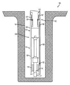
[0004] FIG. 1 is a schematic illustration of a well system that includes
an RFID
drive shaft actuation system according to one aspect of the present
disclosure.
[0005] FIG. 2A is a cross-sectional side view of the RFID drive shaft
actuation
system according to one aspect of the present disclosure.
[0006] FIG. 2B is a cross-sectional side view of the RFID drive shaft
actuation
system of FIG. 2A with a first RFID tag in a detectable range according to one
aspect
of the present disclosure.
[0007] FIG. 2C is a cross-sectional side view of the RFID drive shaft
actuation
system of FIG. 2A with a second RFID tag in a detectable range according to
one
aspect of the present disclosure.
[0008] FIG. 3 is a cross-sectional side view of an RFID drive shaft
actuation
system according to another aspect of the present disclosure.
[0009] FIG. 4 is a block diagram depicting an example of a signal
processing
module according to one aspect of the present disclosure.
Detailed Description
[0010] Certain aspects and examples of the disclosure are directed to an
assembly for actuating an internal bend or tilt angle of a drive shaft of a
bottom hole
assembly using radio frequency identification ("RFID"). In directional
drilling, using
an internal bend (or tilting) of the drive shaft of a mud motor (or drilling
motor) to
control a drilling direction can provide improved hole quality and minimize
fatigue to
the bottom hole assembly housing.
2
CA 02983662 2017-10-23
WO 2016/204756 PCT/US2015/036296
[0011] An RFID drive shaft actuation system can allow for the angular
position
(or bend angle) of the drive shaft to be adjusted from the surface of the
wellbore.
Elements of the RFID drive shaft actuation system can be positioned on a
housing of
a bottom hole assembly and can include RFID tags that can have a specific
signature or signal associated with a bend angle of the drive shaft. The RFID
tags
can be located on a piston that is slideably coupled to the inside of the
housing of the
bottom hole assembly. The piston can be supported by a spring that exerts a
restoring force against the piston. An opposing force can be exerted against
the
piston in a direction opposite the restoring force of the spring. The
differential force
exerted on the piston (e.g., the difference between the opposing force and the
restoring force of the spring) can determine the location of the piston along
a length
of the housing. The location of the piston along the length of the housing can
determine which RFID tag, if any, located on the piston is in a detectable
range of an
RFID reader. The RFID reader can be positioned on the housing of the bottom
hole
assembly. The opposing force can be controlled (e.g., increased or decreased)
at
the surface of the wellbore. For example, the opposing force can be a force
exerted
by the drilling fluid (or mud) introduced from the surface into the housing of
the
bottom hole assembly. In some aspects, the opposing force can be an electro-
magnetic force or a gravitational force.
[0012] The location of the piston, and the RFID tags located on the
piston, can
be controlled from the surface by increasing or decreasing the opposing force
exerted on the piston. When the differential force is such that one of the
RFID tags
on the piston is located in a detectable range of the RFID reader the RFID tag
can
transmit its signature to the RFID reader. The signature can correspond to
select
bend angle (or bend setting) of the drive shaft. The RFID reader can receive
the
3
CA 02983662 2017-10-23
WO 2016/204756 PCT/US2015/036296
signature from the RFID tag and can transmit the signature to a computing
device
such as a signal processing module via a wired communication link. The signal
processing module can determine the select bend angle associated with the
signature and output a command to a motor to position the drive shaft at the
select
bend angle. The motor can be coupled to a gear that mates with an outer
surface of
a bearing cylinder. The bearing cylinder can have an eccentric inner diameter
that is
offset from an outer diameter of the bearing cylinder. The drive shaft can be
positioned within a bored hole of the bearing cylinder that corresponds to the
eccentric inner diameter. The rotational position of the bearing cylinder can
determine the bend angle of the drive shaft. The motor can position the
eccentric
bearing cylinder such that the drive shaft is positioned at the select bend
angle
associated with the signature of the RFID tag in the detectable range of the
RFID
reader.
[0013] FIG. 1 depicts a cross-sectional side view of one embodiment of a
system 100 that can include an RFID drive shaft actuation system 102. The RFID
drive actuation system 102 can be positioned in a wellbore 104 that extends
through
various earth strata through a hydrocarbon bearing subterranean formation. A
drill
string 106 for directional drilling can be positioned in the wellbore 104. The
drill
string 106 can include a bottom hole assembly 108 having a power section 110,
a
coupling section 112, a drive shaft 114, a bearing assembly 116, and a drill
bit 117.
The bottom hole assembly 108 can determine the characteristics of the
borehole, for
example the borehole shape and direction. The drive shaft 114 can be
positioned at
a bend angle. The bend angle can control the angle of the drill bit 117 and
the angle
of the drilled hole. The drive shaft 114 can be positioned in a bored hole
within the
bearing assembly 116.
4
CA 02983662 2017-10-23
WO 2016/204756 PCT/US2015/036296
[0014] Some elements of the RFID drive shaft actuation system 102 can be
positioned above the power section 110 of the bottom hole assembly 108 due to
space limitation around the drilling motor drivetrain. Some elements of the
RFID
drive shaft actuation system 102 can be located elsewhere on the bottom hole
assembly 108, for example at the coupling section 112. The system 102 can
include
an RFID reader or reader 120, a motor 122, a signal processing module 126, and
more RFID tags 127 positioned on a piston 115.
[0015] The piston 115 can be slideably coupled to an inner surface of a
housing 124 of the bottom hole assembly 108. In some aspects, the piston 115
can
be coupled to a sleeve of the bottom hole assembly 108. The RFID reader 120
also
can be positioned on the housing 124 of the bottom hole assembly 108. The RFID
reader 120 can be in communication with a signal processing module 126 via a
wired or wireless communication link. A wired communication link can include
interfaces such as Ethernet, USB, IEEE 1394, or a fiber optic interface. A
wireless
communication link can include wireless interfaces such as IEEE 802.11,
Bluetooth,
or radio interfaces for accessing cellular telephone networks (e.g.,
transceiver/antenna for accessing a CDMA, GSM, UMTS, or other mobile
communications network). The signal processing module 126 can be positioned in
a
cavity of the housing 124, on an inner or an outer surface of the housing 124,
or
other suitable locations on the bottom hole assembly 108. In some aspects, the
signal processing module 126 can be positioned away from the bottom hole
assembly 108, for example but not limited to, at the surface of the wellbore
or on a
tool positionable within the wellbore. The signal processing module 126 can be
in
communication with the motor 122 via a wired communication link 128. In some
= CA 02983662 2017-10-23
WO 2016/204756
PCT/US2015/036296
aspects, a wireless communication link can be used instead of the wired
communication link 128.
[0016]
A restoring force can be exerted by a spring supporting the piston 115.
An opposing force can act on the piston 115 to cause the piston 115 to slide
within
the housing 124 against the restoring force of the spring 144.
For example, the
opposing force can be from the pressure of the drilling fluid, a gravitational
force
acting on a weight attached to an end of the piston 115, or an electro-
magnetic force.
The opposing force can cause the piston 115 to slide within the housing 124 to
compress the spring and move an RFID tag 127 on the piston 115 within a
detectable range of the RFID reader 120. The RFID reader 120 can receive a
signature (or a signal) from the RFID tag 127 when the RFID tag 127 is in the
detectable range. For example, the signature can be associated with a select
bend
angle of the drive shaft 114. The RFID reader 120 can transmit the signature
received from one of the RFID tags 127 to the signal processing module 126 via
the
communication link. More than one RFID tag may be positioned on the piston 115
and each RFID tag may contain a different bend setting of the drive shaft 114.
The
RFID reader 120 can receive the signature from the RFID tag 127 that is in the
detectable range. The RFID tags 127 can be positioned such that only one RFID
tag
127 may be in the detectable range of the RFID reader 120 at a given time. In
other
aspects, RFID tags can be positioned such that a certain number of RFID tags
are in
the detectable range of the RFID reader 120 at a given time.
[0017]
The signal processing module 126 can determine the select bend
angle or other information corresponding to the signature. The signal
processing
module 126 can transmit a command to a motor 122 to position the drive shaft
114
at a bend angle corresponding to the select bend angle associated with the
RFID tag
6
CA 02983662 2017-10-23
WO 2016/204756 PCT/US2015/036296
127. The motor 122 can rotate the bearing assembly 116 to a specific position
associated with the select bend angle of the drive shaft 114. In some aspects,
the
information stored on the RFID tag 127 can be a rotational position of the
bearing
assembly 116.
[0018] FIG.
2A depicts a cross-sectional side view of an RFID drive shaft
actuation system 102 for controlling a bend angle of a drive shaft 114 of a
bottom
hole assembly 108 according to one aspect. The drive shaft 114 is positioned
within
a bored hole of a bearing cylinder 132 of the bearing assembly 116. The drive
shaft
114 controls the position of the drill bit 117. The bored hole of the bearing
cylinder
132 can define an inner diameter of the bearing cylinder 132. The inner
diameter of
the bearing cylinder 132 can be eccentric. The
inner diameter of the bearing
cylinder 132 can define an inner axis 146. The outer diameter of the bearing
cylinder
132 can have an axis that is aligned with a center axis 148 of the housing
124. The
inner axis 146 off the bearing cylinder 132 can be offset from the axis of the
outer
diameter (and the center axis 148).
[0019] The
RFID drive shaft actuation assembly 102 can include the piston
115 slideably positioned within the housing 124 of the bottom hole assembly
108.
Three RFID tags 136, 138, 140 are depicted as positioned on the piston 115.
Only
three RFID tags are discussed herein to simplify illustration, but more or
fewer RFID
tags may be used in this or other embodiments described below in place of or
in
addition to RFID tags 136, 138, 140. Each RFID tag can include information,
for
example a select bend angle, signature, or command to tilt the drive shaft 114
to a
specific bend angle. The number of RFID tags positioned on the piston 115 can
determine the increments of the bend angle of the drive shaft 114 that may be
selected. For example, the RFID tags 136, 138, 140 can be positioned in rings
7
= CA 02983662 2017-10-23
WO 2016/204756
PCT/US2015/036296
around the piston 115, in a spiral around the piston 115, and/or mounted to
the
piston 115 in other suitable positions. The RFID tags 136, 138, 140 can be
positioned relative to one another so as to prevent signal interference
between each
RFID tag. The signal strength and interference of each RIFD tag 136, 138, 140
can
depend on the transmitted power, frequency, the RFID tag orientation, and the
surrounding environment.
[0020] The RFID tags 136, 138, 140 can be passive tags that do
not require
their own internal power source. A passive tag can use the radio energy
transmitted
by the RFID reader 120 to power the tag and transmit the information stored on
the
tag (e.g. the signature) to the RFID reader 120 when the tag is in the
detectable
range. For example, the RFID reader 120 can continuously transmit radio waves
or
a signal that can be converted by an antenna of the passive tag into
electricity that
can power a microchip in the passive tag. In some aspects, the microchip can
change the load on the antenna of the passive tag to transmit (or reflect
back) to the
RFID reader 120 an altered signal. The altered signal can correspond to the
information stored on the passive tag. A characteristic of the altered signal
can be
associated with the signature of the passive tag. The characteristic of the
altered
signal can include, for example a specific magnetic field, a specific wave
form, or a
specific mode that is associated with the passive tag.
[0021] In some aspects, the RFID tags 136, 138, 140 can be
active tags, or a
combination of active and passive tags. For example, an active tag on the
piston
115 can include a signature associated with a first position of the bearing
cylinder
132 while a passive tag positioned on the piston 115 can include a signature
associated with a second position of the bearing cylinder 132. For example,
the first
position of the bearing cylinder 132 can align the inner axis 146 of the
bearing
CA 02983662 2017-10-23
WO 2016/204756 PCT/US2015/036296
cylinder 132 and the center axis 148 of the housing 124 and the second
position can
angle the inner axis 146 away from the center axis 148 to define a bend angle
of the
bearing cylinder 132. An active tag can include a battery and can periodically
transmit its identification signal when in the presence of the RFID reader
120. Active
tags can be more expensive than passive tags. In some aspects, passive tags
can
have a smaller detectable range associated with the RFID reader 120 than the
active
tags.
[0022] In some aspects, the RFID reader 120 can be passive and can receive
radio signals from passive RFID tags or active RFID tags as opposed to
transmitting
a signal to interrogate an RFID tag. The RFID reader 120 can be located at a
single
point on the housing 124, can be located at multiple points on the housing
124, or
can be a partial or complete circular sleeve attached to the housing 124.
[0023] The piston 115 is supported by a spring 144. The piston 115 can
slide
inside the housing 124 against a restoring force of the spring 144 due to an
opposing
force acting on the end 142 of the piston 115. The spring 144 can be a
compression
spring. The spring 144 has a specific spring stiffness that is known and the
force
required to move the piston 115 a certain distance along a length of the
housing 124
can be represented by the relationship F=kx, where F is the spring force, k is
the
spring stiffness, and x is the distance the spring 144 is compressed. The
distance x
the spring is compressed can be determined and the position of the spring 144
relative to the housing 124 can be determined. The position of the piston 115
and
each of the RFID tags 136, 138, 140 can be determined in relation to the RFID
reader 120 on the housing 124 based on the position of the spring 144 relative
to the
housing 124.
9
CA 02983662 2017-10-23
WO 2016/204756 PCT/US2015/036296
[0024] The
position of the piston 115 and the RFID tags 136, 138, 140 can be
controlled from the surface by adjusting the opposing force exerted on the end
142
of the piston 115. In some aspects, the opposing force can be from the
drilling fluid
(or mud) introduced into the housing from the surface. The opposing force of
the
drilling fluid can be controlled by a pump located at the surface. In some
aspects,
the drilling fluid introduced downhole can include magnetized drilling fluid
that can
change a magnetic field, the magnetic field can act on the piston 115 and
cause it to
slide within the housing 124. The strength of the magnetic field can be
altered by
adjusting the magnetization of the drilling fluid prior to its injection
downhole. In some
aspects, the piston 115 can include a weight positioned at the end 142 of the
piston
115. The force exerted on the spring 144 by the weight of the piston 115 can
be
dependent on the inclination of the bottom hole assembly 108. For example, the
full
force of the weight of the piston 115 can be applied to the spring 144 when
drilling
downwards in a vertical drilling. In some aspects, the weight of the piston
115 is not
acting on the spring 144 during horizontal drilling.
[0025] The
opposing force applied to the end 142 of the piston 115 can be
increased or decreased such that at least one of the RFID tags 136, 138, 140
is
moved into a detectable range of the RFID reader 120. The RFID tags 136, 138,
140
can each transmit a signature to the RFID reader 120 when in a detectable
range,
the signature can be associated with a select bend angle of the drive shaft
114. The
RFID reader 120 can transmit the signature it received from the RFID tag to
the
signal processing module 126 via a wired communication link 150. The signal
processing module 126 can receive power from a power source, such as a battery
121. The signal processing module 126 can process the signature and determine
the select bend angle associated with the signature. The signal processing
module
CA 02983662 2017-10-23
WO 2016/204756 PCT/US2015/036296
126 can output one or more instructions to the motor 122 to position the
bearing
cylinder 132 in a position that sets the drive shaft 114 at the select bend
angle
associated with the signature of the RFID tag in the detectable range of the
RFID
reader 120. The signal processing module 126 can output the one or more
instructions to the motor 122 via the wired communication link 128. The signal
processing module 126 can be calibrated to determine the select bend angle
associated with the signature of each RFID tag 136, 138, 140. The signature of
each RFID tag 136, 138, 140 can be a specific voltage change, current change,
or
other suitable signature identifiable by the signal processing module 126.
[0026] In FIG. 2A the RFID tags 136, 138, 140 are shown out of the
detectable range of the RFID reader 120 positioned on a sleeve of the housing
124.
FIG. 2B depicts the RFID drive shaft actuation system 102 of FIG. 2A with the
drive
shaft 114 and the housing 124 in a first position. Specifically, the piston
115 is
positioned such that the RFID tag 140 is located in the detectable range of
the RFID
reader 120 and the drive shaft 114 is positioned at the select bend angle
associated
with the RFID tag 140. FIG. 2C depicts the RFID drive shaft actuation system
102
with the drive shaft 114 and the housing 124 in a second position associated
with the
RFID tag 138. Specifically, the piston 115 is positioned such that RFID tag
138 is
located in the detectable range of the RFID reader 120 and the drive shaft 114
is
positioned at the select bend angle associated with the RFID tag 138.
[0027] As depicted in FIG. 2B, the RFID tag 140 can transmit its signature
to
the RFID reader 120. The RFID reader 120 can transmit the signature it
received
from the RFID tag 140 to the signal processing module 126 via the wired
communication link 150. In some aspects, after receiving the signature from
the
RFID reader 120, the signal processing module 126 can transmit a notification
via a
11
CA 02983662 2017-10-23
WO 2016/204756 PCT/US2015/036296
wired or wireless communication link to a computing device at the surface, The
notification can be transmitted using, for example but not limited to signal
telemetry,
electro-magnetic telemetry, acoustic telemetry, mud-pulse telemetry, or wired
pipe.
The notification can include the information (e.g., the select bend angle)
associated
with the RFID tag 140.
[0028] The signal processing module 126 can determine the signature
received from the RFID reader 120 (the signature associated with the RFID tag
140)
and can transmit a command to the motor 122 via the wired communication link
128.
The command can be an instruction to position the drive shaft 114 at a bend
angle
corresponding to the select bend angle of the RFID tag 140. The inner axis 146
of
the bearing cylinder 132 as compared to the center axis 148 of the housing 124
can
define the bend angle of the drive shaft 114.
[0029] The motor 122 can position the drive shaft 114 at the select bend
angle
by rotating a gear 152 configured to mate with an outside surface 154 of the
bearing
cylinder 132. As the bearing cylinder 132 rotates the bend angle of the drive
shaft
114 can change. The gear 152 can rotate the bearing cylinder 132 to a rotation
position that positions the drive shaft 114 at the select bend angle. In some
aspects,
when the bearing cylinder 132 is positioned such that the drive shaft 114 is
at the
select bend angle associated with the RFID tag in the detectable range, a
locking
mechanism can secure the bearing cylinder 132 in place. In some aspects, a
locking
mechanism can secure the gear 152 in position which can thereby secure the
bearing cylinder 132 in place.
[0030] The signal processing module 126 can receive power from the battery
121. In some aspects, the power source can be a thermal generator, a fluid
generator, a thermo-electric generator, a power supply located on a tool
positioned
12
CA 02983662 2017-10-23
WO 2016/204756 PCT/US2015/036296
within the bottom hole assembly, a power supply located on an add-on sub
assembly, or a power supply located on a measurement while drilling system
attached to the bottom housing assembly, or other suitable power source. The
signal processing module 126 can also provide power to the RFID reader 120 via
a
pass-through wire connection between the RFID reader 120 and the signal
processing module 126. In some aspects, the wired communication link 150 can
also be the pass through wire connection for providing power to the RFID
reader
120. When the RFID reader 120 receives less power the discoverable range of
the
RFID tags 136, 138, 140 can be decreased. The lower the amount of power the
RFID reader 120 draws from the power source the longer the utility of the
power
source (e.g., length of the battery life). In some aspects, the power source
could
provide a greater amount of power, which can increase the detectable range of
the
RFID tags 136, 138, 140 and the accuracy of the RFID reader 120.
[0031] The motor 122 can also receive power via a wired connection passing
between the motor 122 and the signal processing module 126 through the housing
124 of the bottom hole assembly 108. In some aspects, the wired connection can
be
the wired communication link 128. The RFID reader 120, piston 115, and signal
processing module 126 are shown in FIGs. 2A-2C positioned above the power
section 110 of the bottom hole assembly 108. The wired communication link 128
between the signal processing module 126 and the motor 122 can extend from the
signal processing module 126 located above the power section 110, through the
power section 110 and the coupling section 112 (depicted in FIG. 1),
terminating at
the motor 122 positioned at the bearing cylinder 132. The difference between
the
bend angles of the drive shaft 114 can be small and the radial clearance of
the
housing 124 can be minimized to allow RFID reader 120, piston 115, and signal
13
CA 02983662 2017-10-23
WO 2016/204756 PCT/US2015/036296
processing module 126 to be positioned directly above the bearing cylinder 132
at
the coupling section 112 (depicted in FIG. 1). When the signal processing
module
126 is positioned directly above the bearing assembly 116 the wired
communication
link 128 between the signal processing module 126 and the motor 122 can extend
a
shorter distance through the housing 124 as compared to when the signal
processing module 126 is positioned above the power section 110.
[0032] FIG. 3 depicts a cross-sectional side view of an RFID drive shaft
actuation system 300 according to an additional aspect of the disclosure.
Various
elements of the system 300 are positioned at a different portion of a bottom
hole
assembly than those same elements, identfied with the same numerals, in the
system 102 depicted in FIGs. 1-2C. Specifically, the system 300 depicts
certain
elements of the system positioned in a coupling section 302 of a bottom hole
assembly 304 as opposed to above a power section of the bottom hole assembly
304 (as depicted in FIGs. 1-2C). As depicted in FIG. 3, the RFID reader 120,
the
piston 115, the RFID tags 136, 138, 140, the wired communication link 150, and
the
signal processing module 126 can be positioned in the coupling section 302 of
the
bottom hole assembly 304. By positioning the signal processing module 126 at
the
coupling section 302 the signal processing module 126 can be positioned closer
to
the motor 122. A wired communication link 306 can extend between the signal
processing module 126 and the motor 122. The wired communication link 306 can
function in the same way as the wired communication link 128 described with
respect to FIGs. 1-2C. The wired communication link 306 can extend a shorter
distance than the wired communication link 128 depicted in the system 102 of
FIGs.
1-2C. In some aspects, the shorter distance between the signal processing
module
126 and the motor 122 can decrease the chances of damaging the wired
14
CA 02983662 2017-10-23
WO 2016/204756 PCT/US2015/036296
communication link 128 and can provide for easier installation of the system
300.
The elements of the system 300, including but not limited to, the RFID reader
120,
the piston 115, the RFID tags 136, 138, 140, the wired communication link 150,
and
the signal processing module 126, can function as described above with respect
to
FIGs. 1-2C. Other elements of the system 300 labelled with the same numerals
as
those used in FIGs. 1-2C can be considered the same element referenced in
FIGs.
1-2C.
[0033] FIG. 4 is a block diagram depicting an example of a signal
processing
module 126 according to one aspect of the present disclosure. The signal
processing module 126 includes a processing device 202, a memory device 206,
and a bus 204. The processing device 202 can execute one or more operations
for
determining a select bend angle associated with a signal and transmitting
instructions to a motor. The processing device 202 can execute instructions
208
stored in the memory device 206 to perform the operations. The processing
device
202 can include one processing device or multiple processing devices. Non-
limiting
examples of the processing device 202 include a Field-Programmable Gate Array
("FPGA"), an application-specific integrated circuit ("ASIC"), a
microprocessor, etc.
[0034] The processing device 202 can be communicatively coupled to the
memory device 206 via the bus 204. The non-volatile memory device 206 may
include any type of memory device that retains stored information when powered
off.
Non-limiting examples of the memory device 206 include EEPROM, flash memory,
or any other type of non-volatile memory. In some aspects, at least some of
the
memory device 206 can include a medium from which the processing device 202
can read the instructions 208. A computer-readable medium can include
electronic,
optical, magnetic, or other storage devices capable of providing the
processing
CA 02983662 2017-10-23
WO 2016/204756 PCT/US2015/036296
device 202 with computer-readable instructions or other program code. Non-
limiting
examples of a computer-readable medium include (but are not limited to)
magnetic
disk(s), memory chip(s), ROM, RAM, an ASIC, a configured processor, optical
storage, or any other medium from which a computer processor can read
instructions. The instructions may include processor-specific instructions
generated
by a compiler or an interpreter from code written in any suitable computer-
programming language, including, for example, C, C++, C#, etc.
[0035] Example #1: A system may include a bearing cylinder that has a
bored
hole for receiving a drive shaft. The bored hole can correspond to an
eccentric inner
diameter of the bearing cylinder. A radio frequency identification (RFID) tag
may be
positioned on a piston that may be slideably coupled to a housing of a bottom
hole
assembly. A motor may be positioned within the housing of the bottom hole
assembly to rotate the bearing cylinder and position the drive shaft at a bend
angle.
An RFID reader may be coupled to the housing of the bottom hole assembly to
detect the RFID tag in response to the RFID tag being in a detectable range of
the
RFID reader and to transmit information about the RFID tag to control the
motor.
[0036] Example #2: The system of Example #1 may have the motor coupled
to a gear. The gear may be positioned to mate with an outer surface of the
bearing
cylinder.
[0037] Example #3: The system of any of Examples #1-2 may also include a
signal processing module coupled to the RFID reader. The signal processing
module
may have a non-transitory, computer-readable medium that includes
instructions.
The instructions may be executable for causing the signal processing module to
receive the information about the RFID tag from the RFID reader. The
instructions
may also cause the signal processing module to determine a select bend angle
16
CA 02983662 2017-10-23
WO 2016/204756 PCT/US2015/036296
associated with the information about the RFID tag and transmit a command to
the
motor to rotate the bearing cylinder and position the drive shaft at the
select bend
angle.
[0038] Example #4: The system of any of Examples #1-3 may include a spring
that supports the piston. The spring may exert a restoring force on the
piston.
[0039] Example #5: The system of any of Examples #1-4 may have the piston
be slideable in response to a differential force. The differential force may
be based
on the restoring force of the spring and an opposing force.
[0040] Example #6: The system of any of Examples #1-5 may include a power
source for providing power to a signal processing module. The signal
processing
module may be communicatively coupled to the RFID reader.
[0041] Example #7: An assembly may include a bearing cylinder positioned
within a housing of a bottom hole assembly. The bearing cylinder may include a
bored hole that corresponds to an eccentric inner diameter of the bearing
cylinder. A
piston may be slideably coupled to the housing of the bottom hole assembly.
The
piston may include a radio frequency identification (RFID) tag to transmit
information
to an RFID reader. The information may include a select bend angle of a drive
shaft
positioned within the bore hole. A spring may exert a restoring force on the
piston.
A motor may be coupled to the bearing cylinder to rotate the bearing cylinder
in
response to receiving command from a signal processing module. The signal
processing module may be coupled to the RFID reader to determine the select
bend
angle.
[0042] Example #8: The assembly of Example #7 may include a gear coupled
to the motor. The motor may be positioned to mate with an outside surface of
the
bearing cylinder.
17
CA 02983662 2017-10-23
WO 2016/204756 PCT/US2015/036296
[0043] Example #9: The assembly of any of Examples #7-8 may include a
power source for providing power to the signal processing module.
[0044] Example #10: The assembly of any of Examples #7-9 may include an
additional RFID tag disposed on the piston for transmitting additional
information to
the RFID reader.
[0045] Example #11: The assembly of any of Examples #7-10 may feature the
bearing cylinder having an outer diameter that includes an axis that is
aligned with a
central axis of the housing of the bottom hole assembly.
[0046] Example #12: The assembly of any of Examples #7-12 may feature
the piston being slideable in response to a differential force. The
differential force
may be based on the restoring force of the spring and an opposing force.
[0047] Example #13. A method may include transmitting, by a radio
frequency
identification (RFID) tag, information about the RFID tag. An RFID reader may
receive the information about the RFID tag in response to the RFID tag being
in a
detectable range of the RFID reader. A signal processing module may determe a
select bend angle associated with the information. The signal processing
module
may also generate a command to rotate a bearing cylinder to position a drive
shaft at
the select bend angle.
[0048] Example #14: The method of Example #13 may also include
transmitting to a motor, by a communication link, the command to rotate the
bearing
cylinder to position the drive shaft at the select bend angle.
[0049] Example #15: The method of any of Examples #13-14 may also
include transmitting, by a communication link, the information about the RFID
tag
from the RFID reader to the signal processing module.
18
CA 02983662 2017-10-23
WO 2016/204756 PCT/US2015/036296
[0050] Example #16: The method of any of Examples #13-15 may also
include rotating, by a gear positioned to mate with a surface of the bearing
cylinder,
the bearing cylinder to position the drive shaft at the select bend angle.
[0051] Example #17: The method of any of Examples #13-15 may also
include positioning the RFID tag in the detectable range of the RFID reader.
[0052] Example #18: The method of any of Examples #13-17 may also
include positioning the RFID tag in the detectable range of the RFID reader by
exerting a force on a piston coupled to a housing of a bottom hole assembly.
In
addition, the RFID tag may be disposed on the piston.
[0053] Example #19: The method of Example #18 may include exerting the
force on the piston coupled the housing of the bottom hole assembly by
injecting
drilling fluid from a surface.
[0054] Example #20: The method of any of Examples #13-17 may also
include moving a piston coupled to a housing of a bottom hole assembly by
injecting
drilling fluid from a surface. In addition, the RFID tag may be disposed on
the piston.
[0055] The foregoing description of certain examples, including
illustrated
examples, has been presented only for the purpose of illustration and
description
and is not intended to be exhaustive or to limit the disclosure to the precise
forms
disclosed. Numerous modifications, adaptations, and uses thereof will be
apparent to
those skilled in the art without departing from the scope of the disclosure.
19