Note: Descriptions are shown in the official language in which they were submitted.
CA 02983672 2017-10-20
WO 2016/172651
PCT/US2016/029076
TECHNIQUE FOR FULL-DUPLEX TRANSMISSION IN MANY-
ANTENNA MU-MIMO SYSTEMS
Inventor(s):
Clayton Wells Shepard, Evan J. Everett, Ashutosh Sabharvval, Lin Zhong
CROSS-REFERENCE TO RELATED APPLICATIONS
[0001] This application claims benefit of U.S. Provisional Patent
Application Serial No.
62/152,544, filed April 24, 2015, which is hereby incorporated by reference in
its entirety.
STATEMENT REGARDING FEDERALLY SPONSORED
RESEARCH OR DEVELOPMENT
[00021 This invention was made in part with government support under grant
numbers
CNS0751173, CNS0923479, CNS1012831, CNS1126478, and CNS1218700 awarded by the
National Science Foundation. The government has certain rights in the
invention.
BACKGROUND
[0003] This disclosure generally relates to a method and apparatus for
wireless
communications, and more particularly relates to a technique for full-duplex
transmission in
many-antenna multi-user (MU) multiple-input multiple-output (MIMO) systems.
[0004] Full-duplex wireless communication, in which transmission and
reception occur
at the same time and in the same frequency band, has the potential to as much
as double the
spectral efficiency of traditional half-duplex systems. The main challenge to
full-duplex
communication is self-interference, i.e., a node's transmit signal generates
high-powered
interference to its own receiver. It has been shown that full-duplex operation
may be feasible
for small cells (e.g., small number of users), and the key enabler has been
analog cancellation
of the self-interference in addition to digital cancellation. Analog
cancellation has been
considered a necessary component of a full-duplex system, to avoid self-
interference from
overwhelming a dynamic range of receiver electronics, and swamping the much
weaker
intended signal.
[0005] Many analog cancellation designs have been proposed for single-
antenna and
dual-antenna full-duplex systems. However, current wireless base stations
utilize many
antennas (e.g., up to eight antennas, such as in Long Term Evolution (LTE)
Release 12 based
systems), and next-generation wireless communication systems will likely
employ many
more antennas at base stations. For example, discussions to include 64-antenna
base stations
1
CA 02983672 2017-10-20
WO 2016/172651 PCT/US2016/029076
have already been initiated in 3'd Generation Partnership Project (3GPP)
standardization, and
"massive" antenna arrays with hundreds to thousands of antennas have also been
proposed
for 5th generation (5G) wireless communication systems.
10006] As the number of base-station antennas increases, an important
question is how
to enable full-duplex with a large number of antennas. Full-duplex muti-user
multiple-input
multiple-output (MU-MIMO) communications would enable the base station to
transmit to
multiple downlink users and receive from multiple uplink users, all at the
same time and in
the same frequency band. Full-duplex with many antennas presents both
challenges and
opportunities. The complexity of analog self-interference cancellation
circuitry grows in
proportion to the number of antennas. At the same time, many-antenna full-
duplex also
presents an opportunity: having many more antennas than users served means
that more
spatial resources become available for transmit beamforming to reduce self-
interference.
SUMMARY
[00071 Disclosed embodiments include a method and apparatus for reducing
self-
interference at a many-antenna base station of a multi-user multiple-input
multiple output
(MU-MIMO) full-duplex wireless communication system. The method for self-
interference
reduction presented herein is based upon a digital precoder applied at a
transmitter side of the
many-antenna base station. The digital precoder is generated such that to
minimize a self-
interference power present at a plurality of receive antennas of the many-
antenna base station
or at a plurality of receive antennas of wireless device(s) interfering with
the many-antenna
base station. The digital precoder is applied to transmission data to generate
a modified
version of the transmission data to be transmitted via a plurality of transmit
antennas of the
many-antenna base station. The modified version of the transmission data
represents a
projection of the transmission data onto singular vectors of a self-
interference channel
between the transmit and receive antennas that correspond to smallest singular
values of the
self-interference channel, thus minimizing the self-interference between the
transmit and
receive antennas (i.e., the self-interference power at the receive antennas).
While
transmitting the modified transmission data projected onto the smallest
singular values of the
self-interference channel, data are received at the many-antenna base station
or at the
interfering wireless device(s) containing the minimized level of self-
interference originating
from the transmission data, thus achieving full-duplex communication with the
minimized
level of self-interference.
2
CA 02983672 2017-10-20
WO 2016/172651 PCMIS2016/029076
BRIEF DESCRIPTION OF THE DRAWINGS
[0008] FIG. 1 is an example multi-user full-duplex wireless communication
system, in
accordance with embodiments of the present disclosure.
[0009] FIG. 2 is an example block diagram of self-interference reduction
that may be
implemented at a many-antenna base station of a multi-user full-duplex
wireless
communication system, in accordance with embodiments of the present
disclosure.
[0010] FIGS. 3A, 3B and 3C illustrate operation of a precoder for self-
interference
reduction implemented at the many-antenna base station illustrated in FIG. 2
in a multi-user
full-duplex wireless communication system, in accordance with embodiments of
the present
disclosure.
[0011] FIG. 4 is a block diagram of an example wireless device that may be
employed
in a full-duplex wireless communication system, in accordance with embodiments
of the
present disclosure.
[00121 FIGS. 5A, 5B, 5C and 5D illustrate examples of transmit/receive
antenna
partitions at a base station in a multi-user full-duplex wireless
communication system, in
accordance with embodiments of the present disclosure.
[0013] FIG. 6 is a graph illustrating self-interference reduction for
different partitioning
of antenna array at a base station in a multi-user full-duplex wireless
communication system,
in accordance with embodiments of the present disclosure.
[0014] FIGS. 7A-7B illustrate example graphs of self-interference reduction
achieved
by a precoder for self-interference reduction in a multi-user full-duplex
wireless
communication system, in accordance with embodiments of the present
disclosure.
[0015] FIGS. 8A-8B illustrate example graphs of achievable rates of a full-
duplex
system with a precoder for self-interference reduction vs. a half-duplex
system, in accordance
with embodiments of the present disclosure.
[00161 FIG. 9 illustrates an example of large scale beamforming, in
accordance with
embodiments of the present disclosure
[0017] FIG. 10A illustrates an example full duplex communication between a
large
scale many-antenna base station and user terminals, in accordance with
embodiments of the
present disclosure.
[0018] FIG. 10B illustrates an example of channel state information (CSI)
collection in
full duplex system, in accordance with embodiments of the present disclosure.
3
CA 02983672 2017-10-20
WO 2016/172651 PCT/US2016/029076
[0019] FIG. 11 is a flow chart illustrating a method that may be performed
at a many-
antenna base station of a multi-user full-duplex wireless communication
system, in
accordance with embodiments of the present disclosure.
[0020] The figures depict embodiments of the present disclosure for
purposes of
illustration only. One skilled in the art will readily recognize from the
following description
that alternative embodiments of the structures and methods illustrated herein
may be
employed without departing from the principles, or benefits touted, of the
disclosure
described herein.
DETAILED DESCRIPTION
[0021] The techniques described herein may be used for various wireless
communication systems, including communication systems that are based on an
orthogonal
multiplexing scheme. Examples of such communication systems include Spatial
Division
Multiple Access (SDMA), Time Division Multiple Access (TDMA), Orthogonal
Frequency
Division Multiple Access (OFDMA) systems, Single-Carrier Frequency Division
Multiple
Access (SC-FDMA) systems, and so forth. An SDMA system may utilize
sufficiently
different directions to simultaneously transmit data belonging to multiple
user terminals. A
TDMA system may allow multiple user terminals to share the same frequency
channel by
dividing the transmission signal into different time slots, each time slot
being assigned to
different user terminal. An OFDMA system utilizes orthogonal frequency
division
multiplexing (OFDM), which is a modulation technique that partitions the
overall system
bandwidth into multiple orthogonal sub-carriers. These sub-carriers may also
be called tones,
bins, etc. With OFDM, each sub-carrier may be independently modulated with
data. An SC-
FDMA system may utilize interleaved FDMA (1FDMA) to transmit on sub-carriers
that are
distributed across the system bandwidth, localized FDMA (LFDMA) to transmit on
a block
of adjacent sub-carriers, or enhanced FDMA (EFDMA) to transmit on multiple
blocks of
adjacent sub-carriers. In general, modulation symbols are created in the
frequency domain
with OFDM and in the time domain with SC-FDMA.
[0022] The teachings herein may be incorporated into (e.g., implemented
within or
performed by) a variety of wired or wireless apparatuses (e.g., nodes). In
some
embodiments, a node comprises a wireless node. Such wireless node may provide,
for
example, connectivity for or to a network (e.g., a wide area network such as
the Internet or a
cellular network) via a wired or wireless communication link. In some
embodiments, a
wireless node implemented in accordance with the teachings herein may comprise
an access
4
CA 02983672 2017-10-20
WO 2016/172651 PCT/US2016/029076
point or an access terminal.
[0023] An access point ("AP") may comprise, be implemented as, or known as
NodeB,
Radio Network Controller ("RNC"), eNodeB, Base Station Controller ("BSC"),
Base
Transceiver Station ("BTS"), Base Station ("BS"), Transceiver Function ("TF"),
Radio
Router, Radio Transceiver, Basic Service Set ("BSS"), Extended Service Set
("ES S"), Radio
Base Station ("RBS"), or some other terminology. In some implementations, an
access point
may comprise a set top box kiosk, a media center, or any other suitable device
that is
configured to communicate via a wireless or wired medium. According to certain
embodiments of the present disclosure, the access point may operate in
accordance with the
Institute of Electrical and Electronics Engineers (IEEE) 802.11 family of
wireless
communications standards.
[0024] An access terminal ("AT") may comprise, be implemented as, or known
as an
access terminal, a subscriber station, a subscriber unit, a mobile station, a
remote station, a
remote terminal, a user terminal, a user agent, a user device, user equipment,
a user station, or
some other terminology. In some implementations, an access terminal may
comprise a
cellular telephone, a cordless telephone, a Session Initiation Protocol
("SIP") phone, a
wireless local loop ("WLL") station, a personal digital assistant ("PDA"), a
handheld device
having wireless connection capability, a Station ("STA"), or some other
suitable processing
device connected to a wireless modem. Accordingly, one or more aspects taught
herein may
be incorporated into a phone (e.g., a cellular phone or smart phone), a
computer (e.g., a
laptop), a portable communication device, a portable computing device (e.g., a
personal data
assistant), a tablet, an entertainment device (e.g., a music or video device,
or a satellite radio),
a television display, a flip-cam, a security video camera, a digital video
recorder (DVR), a
global positioning system device, or any other suitable device that is
configured to
communicate via a wireless or wired medium. According to certain embodiments
of the
present disclosure, the access terminal may operate in accordance with the
IEEE 802.11
family of wireless communications standards.
[0025] Described embodiments include an all-digital method for self-
interference
reduction to enable full-duplex operation in many-antenna multi-user multiple-
input multiple-
output (MU-MIMO) wireless communication systems that employ base stations (or
access
points) with a large number of antennas (e.g., many-antenna base stations).
Unlike most
designs that rely on analog cancelers to suppress self-interference, the
methods presented
herein use digital transmit beamforming to reduce self-interference, providing
cost efficient
CA 02983672 2017-10-20
WO 2016/172651 PCT/US2016/029076
implementation, lower power consumption and more efficient mitigation of self-
interference
in comparison with analog-based approach. The described methods reduce self-
interference
to prevent exciding a dynamic range of a receiver portion of a many-antenna
base station due
to a high level of undesired received signal which prevents accurate operation
of the base
station's receiver. A level of self-interference that is not completely
suppressed at a base
station's transmitter and is present at the receiver (i.e., residual self-
interference at the
receiver) is then cancelled digitally by a digital cancellation unit
implemented at the receiver
portion of the many-antenna base station, as described in more detail below.
[0026] The performance of the described methods for self-interference
reduction can be
evaluated using measurements from, for example, a 72-element antenna array in
both indoor
and outdoor environments. The described methods for self-interference
reduction employed
in full-duplex systems can significantly outperform half-duplex systems
operating in the
many-antenna regime, where a number of antennas used at a base station is much
larger than
a number of users being served simultaneously by the base station.
[0027] Described embodiments relate to many-antenna full-duplex operation
with
current radio hardware that can either send or receive on the same band but
not both, i.e.,
Time Division Duplex (TDD) radios without analog cancellation can be employed.
An all-
digital approach for self-interference reduction is presented in this
disclosure to enable many-
antenna full-duplex communication. In the designs presented herein, an array
of base station
antennas can be partitioned into a set of transmit antennas and a set of
receive antennas, and
self-interference from the transmit antennas to the receive antennas can be
reduced by
transmit beamforming. The methods presented herein can operate on the output
of
algorithms for downlink MU-MIMO (e.g., zero-forcing beamforming) without
modifying
their operation. In some embodiments, the receive antennas are not part of the
base station,
but may be located at one or more wireless devices that interfere with the
base station.
Therefore, the described methods for self-interference reduction can be
implemented to
mitigate a self-interference power at the one or more wireless devices
interfering with the
base station.
[0028] The described methods aim to reduce self-interference at a
transmitter side of
the many-antenna base station to a desired level. The reduced level of self-
interference at the
transmitter leads to a reduced level of self-interference at a receiver side
which helps
avoiding saturation of an analog-to-digital conversion at the receive radio
chain with a
prohibitively high level of receive signal (comprising a desired signal and a
residual self-
6
CA 02983672 2017-10-20
WO 2016/172651 PCT/US2016/029076
interference from the transmitter), which ensures accurate operation at the
receiver.
[0029] In some embodiments, the precoder for self-interference reduction
presented
herein and applied at a downlink of a many-antenna base station can minimize a
total self-
interference power, given a constraint on how many effective antennas (i.e.,
transmit degrees
of freedom) must be preserved. The term "effective antennas" represents a
number of
dimensions available to a physical layer of the many-antenna base station for
downlink
communication (e.g., D-rx dimensions or effective antennas). The presented
precoder
configured to minimize the total self-interference has an intuitive form,
i.e., the precoder for
self-interference reduction represents a projection onto singular vectors of a
self-interference
channel corresponding to DT, smallest singular values.
[0030] The described methods for self-interference suppression enable a
large reduction
in self-interference while sacrificing relatively few effective antennas
(i.e., dimensions for
downlink transmission). It is also shown in illustrative embodiments of the
present disclosure
that the presented self-interference suppression method can provide
significant rate gains
over half-duplex systems in the case when a number of transmit antennas at a
many-antenna
base station is much larger than a number of users being served by the many-
antenna base
station.
[00311 FIG. 1 illustrates an example multi-user full-duplex wireless
communication
system 100, in accordance with embodiments of the present disclosure. A base
station (or
access point) 102 may communicate with Ku p uplink users (or uplink access
terminals) 104
and &own downlink users (or downlink access terminals) 106. The base station
102 may be
equipped with M antennas 108, 110. The base station 102 may use traditional
radios, i.e.,
each of the M antennas can both transmit and receive, but a given antenna
cannot both
transmit and receive at the same time. Therefore, in full-duplex operation, MT
x of the
antennas (e.g., antennas 108) transmit while MRx antennas (e.g., antennas 110)
receive, with
the requirement that Mrx A/fRx M. It should be noted that choice of which
antennas 108,
110 transmit and receive can be adaptively chosen by a scheduler (e.g.,
network scheduler,
not shown in FIG. 1). On the other hand, in half-duplex mode, all antennas
108, 110 are used
for either transmission or reception, i.e., MT x = MR x = M. The vector of
symbols transmitted
by the base station 102 is xi). E CMTX, and the vector of symbols transmitted
by the users
104 is xup E
[0032] For some embodiments, the signal received at the base station 102
may be given
as:
7
CA 02983672 2017-10-20
WO 2016/172651 PCT/US2016/029076
yup = Hupxup + Hsex,p,õõ+ zup, (1)
where Hup e CM a' xKu is the uplink channel matrix, H sell_ E CA/Rxxm-Tx is
the self-interference
channel matrix, and zup E CMR' is the noise at the base station's receiver.
The signal received
by the Kuown downlink users 106 may be given as:
YDown(2)
= HDownxDown HUsrxUp ZDown
where HD.. e C , is the downlink channel matrix, HUsr c Kr,0õ. xlCup
is the matrix of
channel coefficients from the uplink users 104 to the downlink users 106, and
zpowll E CA-D¨ is
the noise at the receiver of each user 106.
[00331 Described embodiments focus on the challenge of self-interference
suppression.
It is generally considered in the present disclosure that Husr= 0. In half-
duplex operation,
equations (1) and (2) can be simplified, i.e., the self-interference term can
be eliminated in
equation (1), and Hup is a M X Ku p matrix and KDown is a KDowaxM matrix. The
signaling
challenge unique to full-duplex operations is how to design XDown (i.e., the
vector of symbols
transmitted by the base station 102) such that the self-interference is below
a defined
threshold, while still providing a high signal-to-interference-plus-noise
ratio (SINR) to the
downlink users 106.
Precoder Design
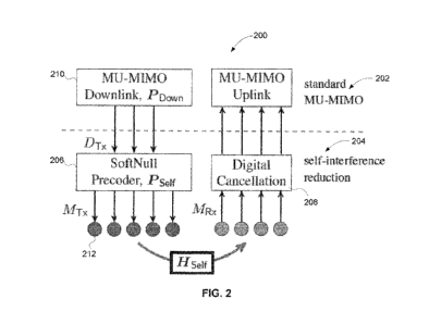
[00341 FIG. 2 illustrates an example block diagram 200 of self-interference
reduction in
a multi-user full-duplex wireless communication system based on a transmit
precoder design,
in accordance with embodiments of the present disclosure. The self-
interference reduction
illustrated in FIG. 2 may be implemented at the many-antenna base station 102
of the multi-
user full-duplex wireless communication system 100 illustrated in FIG. 1. As
illustrated in
FIG. 2, a two-stage approach is applied for self-interference reduction. A
first stage 202
represents standard MU-MIIVIO for which conventional precoding and
equalization
algorithms can be employed. A second stage 204 represents the self-
interference reduction
stage, which reduces self-interference via transmit beamforming at a transmit
side and digital
self-interference cancellation at a receive side. The advantage of the two-
stage approach
illustrated in FIG. 2 is that the presented precoder for self-interference
reduction can be
incorporated as a modular addition to existing MU-MIMO systems.
[00351 As illustrated in FIG. 2, the self-interference reduction stage 204
may comprise
two components: a transmitter-side precoder 206 configured to reduce self-
interference and a
8
CA 02983672 2017-10-20
WO 2016/172651 PCT/US2016/029076
receiver-side digital canceler 208 configured to reduce a remaining level of
self-interference
(i.e., residual self-interference). In some embodiments, the decision on the
partitioning of
transmit and receive antennas (MT,,, MR,c) at the employed many-antenna base
station can be
made by a higher layer operation, e.g., based on the network needs.
[0036] As illustrated in FIG. 2, the downlink precoding may comprise two
stages, a
MU-MIMO downlink precoder 210, PDõ,õ,õ, followed by the self-interference
reduction
precoder 206, PSelf= The goal of the precoder 206, PSelf, , is to suppress
self-interference. The
goal of the downlink precoder 210, P00õ0, is for the signal received by each
user to contain
mostly the signal intended for that user, and as low as possible signals
intended for other
users. The MU-MIMO downlink precoder 210, P
- Down, may control a number of DTõ effective
transmit antennas. The self-interference reduction precoder 206, Psi maps the
signal on the
DT x effective antennas (provided by the downlink precoder 210) to the signal
transmitted on
the MT,, physical transmit antennas 212, as illustrated in FIG. 2.
[0037] Let spown E C00 denotethe vector of symbols that a many-antenna base
station
(e.g., the many-antenna base station 102 illustrated in FIG. 1) allocates for
communication to
each of the Kth,õõ downlink users. In one or more embodiments, both the MU-
MIMO stage
202 and the self-interference reduction stage 204 can be constrained to be
linear, such that
Ppoõ,, is a DTõ)<KDowõ complex-valued matrix and Pseif is a MTxxDrx matrix.
The signal
transmitted on the base station antennas may be then defined as xDown =
PSelfPDownSDown.
[0038] For some embodiments, the MU-MIMO downlink precoder 210, PDowõ, does
not
need to have knowledge of both the self-interference channel Hs elf and the
downlink channel
&own. Instead, the MU-MIMO downlink precoder 210, PE,,,,n, only needs to know
the
effective downlink channel, HEff = HDownPSelf, which is created by the self-
interference
reduction precoder 206, Pself operating on the physical downlink channel
HDown. In one or
more embodiments, the effective downlink channel HEff can be estimated
directly by
transmitting/receiving pilots along the DT, effective antennas. For the MU-
MIMO downlink
precoder 210, P
- Down, algorithms such as minimum mean square error (MMSE) based
beamforming, zero-forcing beamforming or matched filtering can be employed.
For
example, in the case of zero-forcing beamforming, the MU-MIMO downlink
precoder 210,
Ppown, can be defined as the Moore-Penrose (right) pseudoinverse of the
effective downlink
channel HEff, 1.e.,
= pD(ZowFBnF) = a(zFBF)HEff (HEli
Down ffilEff
(3)
p
9
CA 02983672 2017-10-20
WO 2016/172651
PCT/US2016/029076
where a(') is a power constraint coefficient.
[0039] In
accordance with embodiments of the present disclosure, the goal of the self-
interference reduction precoder 206, Pseff is to reduce self-interference
while preserving a
required number of effective antennas, DT, for MU-MIMO downlink transmission.
As
illustrated in FIG. 2, the self-interference reduction precoder 206, PSelf has
D-rx inputs as
effective antennas, and MD, outputs to the physical transmit antennas 212. In
one or more
embodiments, the self-interference reduction precoder 206, PSelf is provided
with information
related to the self-interference channel, HRH., such as estimation
coefficients of the self-
interference channel matrix, Hself. The goal is to minimize the total self-
interference power
while maintaining DT x effective antennas. The choice of minimizing total self-
interference,
rather than choosing a per-antenna metric is twofold. First, minimizing the
total self-
interference gives more freedom in designing the self-interference reduction
precoder 206,
PSelf= Instead of creating nulls to reduce self-interference at specific
antennas, the self-
interference reduction precoder 206, Pseif can optimize placement of nulls
such that each null
can reduce self-interference to multiple receive antennas. Second, minimizing
the total self-
interference power leads to a closed-form solution, which can be efficiently
implemented
with full arithmetic precision and accuracy. In some embodiments, the design
problem for
the self-interference reduction precoder 206, Psi f may be formulated as:
Pseff = arg min 11-iseif PH2
- !IF (4)
subject to PHP = /Dõ,õDT. .
[0040] For some
embodiments, the squared Frobenius norm in equation (4), 2
11.11/7
measures the total self-interference power. The constraint, pup= Dxun , forces
the self-
interference reduction precoder 206, PSejf to have DT,, orthonormal columns,
and hence
ensures that DT x effective antennas are preserved for MU-MTMO downlink
signaling. The
optimization problem given by equation (4) has the closed-form intuitive
solution. The
preferred self-interference reduction precoder 206, PSelf can be constructed
by projecting onto
the D-rx left singular vectors of the self-interference channel corresponding
to the smallest DTx
singular values. Precisely, in some embodiments, the self-interference
reduction precoder
206, Pself may be defined as:
pseff _,11,(AITx -DT+1) 7v(Mm-Dm +2) 7.. IPVI Tx ) (5)
where Hseff = UEVN is the singular value decomposition of the self-
interference channel, U
CA 02983672 2017-10-20
W02016/172651 PCT/US2016/029076
and V are unitary matrices (i.e., matrices of left and right eigenvectors,
respectively), E is a
nonnegative diagonal matrix whose diagonal elements are the ordered singular
values (i.e.,
matrix of eigenvaluies) and v(1) is the i-th column (i.e., i-th eigenvector)
of the matrix V.
Essentially, the self-interference reduction precoder 206, PSeif represents
determining the D-rx-
dimensional subspace of the original transmit space, CMT , which presents the
least amount of
self-interference to the receiver.
100411 Coefficients of the self-interference channel, Hseff can be
estimated based on a
full channel estimation between every transmit antenna and every receive
antenna. The full
channel estimation can be implemented by sending pilots from the transmit
antennas,
receiving the pilots on the receive antennas, and estimating the channel
coefficients based on
the received pilots at each receive antenna. In some embodiments, as
discussed, the receive
antennas may belong to one or more interfering receivers separate from the
many-antenna
base station. In an embodiment, the receivers can be controlled by a network
associated with
the many-antenna base station. Thus, the receive antennas of the one or more
receivers can
be set to overhear the pilots transmitted from the transmit antennas of the
many-antenna base
station, and can be treated as the receive antennas of the many-antenna base
station. In
another embodiment, the one or more receivers interfering with the many-
antenna base
station are not controlled by the network or the many-antenna base station. In
this case, the
transmit antennas of the many-antenna base station would switch to a receive
mode of
operation and listen for one or more signals transmitted from one or more
wireless devices
comprising the receivers interfering with the many-antenna base station.
Coefficients of the
self-interference channel, Hs a between the transmit antennas of the many-
antenna base
station and the one or more interfering wireless devices can be estimated
based on the one or
more signals received at the many-antenna base station. The described methods
for self-
interference reduction can be implemented to mitigate self-interference
between the transmit
antennas of the many-antenna base station and the one or more receivers
separate from the
many-antenna base station that can overhear signals transmitted from the many-
antenna base
station.
[0042] The illustrative embodiment presented in this disclosure illustrates
how the
designed self-interference reduction precoder 206, Pscif reduces self-
interference by
sacrificing effective transmit antennas. FIG. 3A illustrates a 4x8 (M = 32)
planar antenna
array 302 that may be employed at a many-antenna base station. For example,
the space
between adjacent antennas can be half a wavelength. An even (MTõMRõ), (16,16)
division
11
CA 02983672 2017-10-20
WO 2016/172651 PCT/US2016/029076
of transmit and receive antennas is considered. The antenna array 302 can be,
for example,
partitioned via an East-West partitioning, i.e., with 4 x 4 transmit sub-array
304 to the West,
and 4 x 4 receive sub-array 306 to the East, as illustrated in FIG. 3A. For
simplicity, it is
considered that the antennas are point sources in free space, which enables
computation of
the electric field at any point in space via the free-space Green's function.
In the illustrative
embodiment, the channel between antenna in and point in space 17 may be
defined as:
[Hseif ¨ (6)
nm
where rnõ, is a distance between antenna ni and point n, k =-2z is a
wavenumber, and
= .
[0043] FIG. 3B illustrates the radiated field distribution, in the vicinity
of the received
antennas 306, as a function of the number of effective transmit antennas, DTõ.
First, it can be
considered the case where DT ,= 16 ---MTõ, in which no effective antennas are
given up for
the sake of self-interference reduction; it can be observed that all the
receive antennas 306
receive very high level of self-interference. Then, in the case where DT ,=
15, and a single
effective antenna is given up for self-interference reduction, the self-
interference reduction
precoder 206, PSelf essentially steers a single "soft" null directly into the
middle of the receive
array 306. In the case of DT); = 14, the two effective antennas are sacrificed
allowing the self-
interference reduction precoder 206, Pseif to create two soft nulls that
together cover a larger
portion of the receive array 306. As illustrated in FIG. 3B, the trend
continues, i.e., as more
effective antennas DT, are given up for the sake of self-interference
reduction (i.e, the number
of effective transmit antennas, DT, is smaller), the self-interference
reduction precoder 206,
Pseif can have more freedom for creation of a radiated field pattern with a
small level of self-
interference.
[0044] FIG. 3C illustrates the downside of sacrificing more effective
transmit antennas
for self-interference suppression, i.e., reduced transmit gain. FIG. 3C shows
the far field
power gain (e.g., relative to isotropic) that the transmit antenna array 304
can produce in each
direction along the azimuth plane. The considered antenna elements are those
that are
circular patch antennas. In the case of the full system, i.e., D'fx = 16 =Mrx,
a gain of 16 can
be achieved at broadside (e.g., the gain 310). As illustrated in FIG. 3C, the
gain may slowly
decay as the direction falls away from broadside due to the individual patch
elements haying
maximum gain at broadside. As more effective transmit antennas are given up
for the sake of
12
CA 02983672 2017-10-20
WO 2016/172651 PCT/US2016/029076
self-interference reduction, the maximum gain in any direction is reduced
(e.g., see gains 312,
314 and 316 in FIG. 3C for DT,, = 12, D-rx= 8 and DT x = 4, respectively).
[0045] FIG. 4 illustrates various components that may be utilized in a
wireless device
402 that may be employed within the full-duplex wireless communication system
100
illustrated in FIG. 1. The wireless device 402 is an example of a device that
may be
configured to implement the various methods described herein. The wireless
device 402 may
be a many-antenna base station (access point) 102, an uplink user terminal
104, or a downlink
user terminal 106.
[0046] The wireless device 402 may include a processor 404 which controls
operation
of the wireless device 402. The processor 404 may also be referred to as a
central processing
unit (CPU). Memory 406, which may include both read-only memory (ROM) and
random
access memory (RAM), provides instructions and data to the processor 404. A
portion of the
memory 406 may also include non-volatile random access memory (NVRAM). The
processor 404 typically performs logical and arithmetic operations based on
program
instructions stored within the memory 406. The instructions in the memory 406
may be
executable to implement the methods described herein.
[0047] The wireless device 402 may also include a housing 408 that may
include a
transmitter 410 and a receiver 412 to allow transmission and reception of data
between the
wireless device 402 and another wireless node (e.g., another wireless node in
a remote
location). The transmitter 410 and receiver 412 may be combined into a
transceiver 414. One
or more antennas 416 may be attached to the housing 408 and electrically
coupled to the
transceiver 414. The wireless device 402 may also include (not shown) multiple
transmitters,
multiple receivers, and multiple transceivers.
[0048] The wireless device 402 may also include a signal detector 418 that
may detect
and quantify the level of signals received by the transceiver 414. The signal
detector 418
may quantify detection of such signals using total energy, energy per
subcarrier per symbol,
power spectral density and/or other quantification metrics. The wireless
device 402 may also
include a digital signal processor (DSP) 420 for use in processing signals.
[0049] The various components of the wireless device 402 may be coupled by
a bus
system 422, which may include a power bus, a control signal bus, and a status
signal bus in
addition to a data bus.
13
CA 02983672 2017-10-20
WO 2016/172651 PCT/US2016/029076
Antenna Array Partitioning
[0050] Disclosed embodiments include methods for designing a preferred
precoder for
self-interference suppression in full-duplex many-antenna MU-MIMO systems for
a given
/14x x MTx self-interference channel, i.e., the self-interference reduction
precoder 206, -Pscif
illustrated in FIG. 2 and defined by equations (4) and (5). Disclosed
embodiments further
include methods for partitioning an array ofM antennas at a many-antenna base
station (e.g.,
the many-antenna base station 102 illustrated in FIG. 1 that employs the self-
interference
reduction precoder 206, Ps) into a sub-array of MT x transmit antennas and a
sub-array of
MRx receive antennas. Due to the combinatorial nature of the problem, finding
the optimal
antenna sets can be computationally difficult. For example, if M= 72 and Mrõ =
36, then
there are (72` ¨ 4.4 x10²⁰possible combinations of transmit antenna sub-
arrays. Because of
36/
that, empirical insights are employed herein that use traces collected via
channel
measurements to evaluate and compare several heuristic choices for
partitioning the antenna
array at the many-antenna base station.
[0051] Disclosed embodiments include methods for heuristic partitioning of
the antenna
array at a many-antenna base station. Intuitively, it can be recognized that
the self-
interference reduction precoder 206, Pseff may have preferred performance when
a power in
the self-interference channel Hsuf is concentrated within a fewer number of
eigenchannels. It
has been demonstrated both analytically and experimentally that as the spread
of the angles-
of-departure from a transmitter (e.g., transmit sub-array) to a receiver
(e.g., receive sub-array)
is decreased, a signal received at each receive antenna becomes more
correlated. More
correlated received signals may further cause the first few eigenvalues to
become more
dominant, which is desirable for the self-interference reduction precoder 206,
P
¨ Self.
[0052] Contiguous linear partitions of the antenna array (i.e., one side
transmit sub-
array, other side receive sub-array) limit an angular spread of angles-of-
departure to/from the
transmitter to the receiver, since all the interference is coming from only
one "side" of the
antenna array. For example, in the North-South antenna partition illustrated
in FIG. 5B (i.e.,
transmit sub-array is at North, receive sub-array is at South), the angular
spread of angles-of-
arrival is less than 180 degrees for all receive antennas, since all
interference is coming from
the "North" (i.e., from the transmit sub-array).
[0053] FIGS. 5A-5C show several antenna partitions at a many-antenna base
station
based on the above heuristic of linear contiguous partitioning in order to
limit the angular
14
CA 02983672 2017-10-20
WO 2016/172651 PCT/US2016/029076
spread: i.e., East-West, North-South, and Northwest-Southwest partitions are
shown in FIG.
5A, FIG. 5B, and FIG. 5C, respectively. An even split between the number of
transmit and
receive antennas is considered for all antenna partitions. As a comparison,
the interleaved
partition shown in FIG. 5D is also considered. If the heuristic of minimizing
angular spread
is effective, then it would be expected that the interleaved partition is a
near worst-case
partition. In the interleaved partition, receive antennas experience
interference arriving at
every possible angle. In addition to the deterministic interleaved partition,
the comparison is
also made against the average measured performance of 10,000 randomly chosen
partitions.
[0054] To assess the performance of these heuristics, the self-interference
channel
response is directly measured in an anechoic chamber using the 72-element
rectangular array
and a (
>11Rx = (36,36) partition of transmit and receive antenna elements. The self-
interference channel measurements are performed in the anechoic chamber, as
this is the most
repeatable scenario. FIG. 6 illustrates a graph 600 showing the tradeoff
between self-
interference reduction and a number of effective transmit antennas, DT. for
different antenna
partitioning. As the number of effective transmit antennas, DT x decreases
from its maximum
value of DT x = MTx = 36, the amount of self-interference reduction achieved
by the self-
interference reduction precoder 206, Pei f improves. Since DTõ is the number
of effective
antennas preserved for downlink signaling, (M,rx ¨ Dm) is the number of
effective antennas
leveraged for self-interference reduction. As the number of effective transmit
antennas, DTx
decreases, more effective antennas are "given up" for the sake of improved
self-interference
reduction. Therefore, as the number of effective transmit antennas, DT x
decreases, it can be
observed from FIG. 6 an improved self-interference reduction. It can be also
observed in
FIG. 6 that the tradeoff achieved for the contiguous partitions (e.g., plots
604, 606, 608 in
FIG. 6 for the antenna partitions illustrated in FIGS. 5B, 5A, 5C,
respectively) is much better
than that achieved for the random antenna partition (e.g., plot 602 in FIG. 6)
and interleaved
partitions (e.g., plot 610 in FIG. 6 for the antenna partition illustrated in
FIG. 5D).
[0055] Typical analog cancellation circuits may provide 40-50 dB self-
interference
reduction. Therefore, an interesting point of observation in FIG. 6 is how
many effective
antennas can be preserved while achieving more than 50 dB self-interference
reduction
similar to that of an analog canceler. For the random partition (e.g., plot
502), only 6 of the
maximum 36 effective antennas can be preserved while achieving > 50 dB self-
interference
reduction. However, for all of the contiguous antenna partitions, it can be
possible to achieve
> 50 dB self-interference reduction with at least 16 effective antennas
preserved for downlink
CA 02983672 2017-10-20
WO 2016/172651 PCT/US2016/029076
signaling (see plots 604, 606 and 608 in FIG. 6).
[0056] It can be also observed in FIG. 6 that the antenna partition
providing the
preferred performance is the East-West partition (see plot 606 in FIG. 6),
i.e., the antenna
partition illustrated in FIG. 5A. This finding is in line with the heuristic:
among the
considered antenna partitions, the East-West antenna partition is the one with
minimum
angular spread between the transmit and receive partitions, since the East-
West partition
splits the antenna array along its smallest dimension (antenna array is wider
than tall). It can
be further observed from FIG. 6 that the interleaved antenna partition (e.g.,
plot 610)
performs even worse than the average of random antenna partitions (e.g., plot
602),
emphasizing the importance of selecting contiguous partitions. It should be
also noted the
large impact of the antenna partition type on the tradeoff between self-
interference reduction
and the number of effective transmit antennas, DT.. For D.,.õ c [3,22], the
East-West partition
enables the designed self-interference reduction precoder 206, Pseff to
achieve more than 25
dB better self-interference reduction than an average of antenna partitions
chosen at random.
Self-Interference Reduction in Different Scattering Environments
[0057] The scattering environment can have a significant impact on the
performance of
the self-interference reduction precoder 206, PSelf illustrated in FIG. 2 and
defined by
equations (4) and (5). The collected traces can be used in the illustrative
embodiment to
study how the scattering environment impacts the tradeoff between self-
interference
reduction and effective antennas achieved by the self-interference reduction
precoder 206,
Psew. For example, the 72-element antenna array can be utilized, with (M-rx
'MR.) = (36,36),
East-West partition of transmit and receive elements, as illustrated in FIG.
5A. FIG. 7A
compares the tradeoff between a level of self-interference reduction and a
number of
preserved effective transmit antennas, DT x in the outdoor deployment (e.g.,
graph 710) versus
the indoor deployment (e.g., graph 720). The self-interference reduction
achieved for each of
the 36 transmit antennas is shown in FIG. 7A, along with the self-interference
reduction
averaged over all 36 transmit antennas. FIG. 7B shows the empirical cumulative
distribution
function (CDF) of the achieved self-interference reduction, both indoors and
outdoors, for a
selection of values for the number of effective transmit antennas, DT. being
preserved.
[0058] It can be observed in FIG. 7A that, with all 36 effective transmit
antennas
preserved, the self-interference can be only suppressed (passively) by
approximately 20 dB
(in both indoor and outdoor deployments). However, by giving up 16 effective
transmit
16
CA 02983672 2017-10-20
WO 2016/172651 PCT/US2016/029076
antennas and preserving DT, = 20 effective antennas for the downlink signaling
in the
outdoor deployment, the self-interference can be suppressed by more than 50 dB
(see the
graph 710). It can be also noticed in FIG. 7A, however, that the self-
interference reduction in
the outdoor deployment (e.g., the graph 710) is better than the self-
interference reduction in
the indoor deployment (e.g., the graph 720) for the same number of effective
antennas, DTx
preserved for downlink signaling. For example, to achieve 50 dB self-
interference reduction
in the indoor deployment, 24 of the 36 effective transmit antennas may need to
be given up
leaving DT x= 12 for downlink transmission (see the graph 720), as opposed to
16 effective
transmit antennas in the outdoor deployment (see the graph 710). The same
antenna array is
used in both outdoor and indoor environments, the only difference being the
backscattering
environment.
[0059] The reason for better performance in outdoor environments than in
indoor
environments is that the backscattering present in indoor environments reduces
the
correlation of the self-interference among antennas that is present in a low
scattering
environments (i.e., outdoor environments). Less correlation makes it harder to
suppress the
self-interference at multiple antennas without giving up more effective
antennas. More
specifically, the self-interference reduction precoder 206, Psa presented
herein projects a
transmit signal onto Di), singular vectors corresponding to smallest DT,
singular values. In
other words, the self-interference reduction precoder 206, Pseif reduces self-
interference by
avoiding the (MD, ¨DT,) dominant modes (singular values) of the self-
interference channel.
In outdoor deployment, direct paths between antennas dominate any
backscattered paths,
leading to a more correlated self-interference matrix, and hence a large
amount of the overall
channel power resides in the dominant (MT,, ¨ DTx ) modes (singular values).
Therefore, a
significant level of self-interference reduction can be achieved by avoiding
first few dominant
modes. However, in an indoor environment, multipath backscattering tends to
decorrelate a
self-interference channel and thus leads to a more uniform distribution of
power over the
modes (singular values). Therefore, in the indoor environment, a less amount
of self-
interference can be suppressed by avoiding only the (MT, ¨ Dm) most dominant
modes
(singular values).
[0060] FIG. 7B shows the empirical CDF of the achieved self-interference
reduction,
both in indoor and outdoor environments, for a selection of values for the
number of effective
antennas, DT, preserved for downlink signaling (e.g., CDF plots 732, 734, 736,
738, 740, 742
for DTx = 12, 20, 28 in outdoor and indoor environments). It can be observed
in FIG. 7B that
17
CA 02983672 2017-10-20
WO 2016/172651
PCT/US2016/029076
for small number of effective transmit antennas, Dm there is much more
variation in the
achieved self-interference reduction in outdoor deployment than in indoor
deployment. For
example, for outdoor deployment with Dm= 12 (e.g., plot 732), the self-
interference
reduction for a given antenna can be between 62 dB and 90 dB, which is a
difference of 28
dB. However, for the indoor deployment, there is much less variation for level
of self-
interference reduction. For example, for indoor deployment with Dm = 12 (e.g.,
plot 734),
the difference between best and worst self-interference reduction is only
approximately 10
dB.
[00611 More variation of self-interference reduction in outdoor
environments than in
indoor environments is also due to less backscattering outdoors than indoors.
In outdoor
environments, the backscattering is nearly nonexistent and direct paths
between transmit and
receive antenna dominate even for small number of effective transmit antennas,
DTx. The
characteristics of the direct-path self-interference channel seen by each
receive antenna may
vary substantially. For example, a subset of receive antennas that are nearest
transmit
antennas may notice less correlation among the transmit antennas (because of a
smaller
angular spread) than another subset of receive antennas farther away from the
transmit
antennas. In indoor environments, however, for a smaller number of effective
transmit
antennas, Dix the self-interference can be dominated by backscattered paths.
Unlike direct
paths, characteristics of the backscattered paths cause less variation in a
self-interference
channel seen by each receive antenna. Therefore, for a small number of
effective transmit
antennas, DTõ, it is expected to observe more variation in self-interference
reduction over the
antenna array in outdoor environments than in indoor environments.
Achievable Rate Gains of Full-Duplex versus Half-Duplex
[0062] FIGS. 8A-8B show uplink, downlink, and sum rates achieved in full-
duplex
systems where the self-interference suppression presented herein is employed
(i.e., the self-
interference reduction precoder 206, Pseir illustrated in FIG. 2 and defined
by equations (4)
and (5)) as a function of a number of preserved effective transmit antennas, D-
rx. The
achievable rates of the self-interference suppression method presented in this
disclosure are
compared to that of half-duplex system as well as with the theoretically ideal
full-duplex
system. It is considered in the illustrative embodiment that a number of
uplink and downlink
clients (users) can be the same and both equal to four, i.e., Kup = /cow, = K
= 4.
[00631 FIG. 8A illustrates performance results (achievable rates) for
channels collected
in outdoor deployment. The downlink rate achieved by the presented self-
interference
18
CA 02983672 2017-10-20
WO 2016/172651
PCT/US2016/029076
suppression scheme (see plot 802) increases as a number of preserved effective
transmit
antennas, DD, increases, since more effective transmit antennas become
available to
beamform and thus create an improved signal-to-interference-plus-noise ratio
(SINR) to
downlink clients. However, as the number of preserved effective transmit
antennas, DTx
increases the uplink rate decreases (see plot 804) because the self-
interference suppression
scheme of the present disclosure can suppress less self-interference when more
effective
transmit antennas are used for downlink beamforming. It can be observed from
FIG. 8A that
once the number of preserved effective transmit antennas, DT, is less than
approximately 12,
the incremental gain in uplink rate from giving up each additional effective
transmit antenna
is only negligible (see plot 804). For example, at DT, = 12, the self-
interference can be
sufficiently suppressed to no longer overwhelm the receiver, and digital
cancellation (e.g.,
digital cancellation 208 shown in FIG. 2) can remove remaining self-
interference. Reducing
the number of effective transmit antennas, DT, below 12 improves the uplink
rate only
slightly but greatly decreases the downlink rate (see plot 802 for Dm < 12).
It can be also
observed from FIG. 8A (see sum rate plot 806 representing the sum of uplink
rate 804 and
downlink rate 802) that there is a range of values for the number of effective
transmit
antennas, DT, for which the self-interference suppression scheme of the
present disclosure
outperforms half-duplex both for the uplink and the downlink signaling. It can
be noticed
that the self-interference suppression scheme of the present disclosure
outperforms half-
duplex communication for DTx E [5,28], achieving peak performance at DTx = 18.
For
example, the achieved rate at DTx = 18 is 23% better than that for half-duplex
communication.
[00641 FIG. 8B shows performance of the presented self-interference
suppression
scheme for indoor deployment. It can be observed that in indoor environments
the self-
interference suppression scheme of the present disclosure outperforms half-
duplex
communication for all values of the number of effective antennas, DT,
preserved for
downlink signaling, with the best performance for DTx = 14, for which a 62%
gain over half-
duplex is achieved (see sum rate plot 808 representing sum of uplink rate 810
and downlink
rate 812). At first, it seems surprising that the gains over half-duplex are
better indoors than
outdoors, when FIG. 7A shows that the self-interference reduction achieved in
outdoor
environments is better than that achieved in indoor environments. The
difference is that the
path loss for the channels measured indoors was much less than that measured
outdoors. The
clients indoors were necessarily placed closer to the array (e.g., 10-25 ft.)
because of limited
space, but outdoors were placed much farther (e.g., 30-50 ft.). Full-duplex
communication
19
CA 02983672 2017-10-20
WO 2016/172651
PCT/US2016/029076
always becomes more challenging as path loss increases. Larger path loss means
the uplink
signal is weaker, and therefore more self-interference reduction is required
to make the self-
interference commensurate in power to the uplink signal.
[0065] For the self-interference suppression scheme of the present
disclosure, larger
path loss means more effective transmit antennas may need to be given up to
achieve better
self-interference reduction. Larger path loss also means that more effective
transmit antennas
are needed to achieve sufficient signal strength on the downlink. Therefore,
the cost of using
effective transmit antennas for the sake of reducing self-interference becomes
greater.
Because the path loss was greater in the outdoor deployment than the indoor
deployment, the
gains of the self-interference suppression scheme presented herein are less
for the outdoor
deployment than for the indoor deployment. Even though the achieved self-
interference is
better outdoors than indoors, the benefit of better suppression does not
compensate for the
greater path loss.
[0066] The self-interference suppression scheme presented in this
disclosure enables
full-duplex operation with current base station radios without requiring
additional circuitry
for analog cancellation. The presented self-interference suppression scheme is
based on that
the self-interference need not be perfectly nulled; it is only needed to
sacrifice a minimal
number of effective antennas required to sufficiently suppress the self-
interference. It is
shown in the present disclosure that sufficient level of self-interference
reduction can be
achieved while only using a portion of effective transmit antennas for self-
interference
suppression.
Large Scale Beamforming with Full Duplex
[0067] Disclosed embodiments further include methods to combine large scale
beamforming with full duplex. In some embodiments, large scale beamfoming can
be
implemented at a many-antenna base station (e.g., the many-antenna base
station 102
illustrated in FIG. 1) where transmission/reception over narrow beams of space
can be
performed by a large number of transmit/receive antennas of the many-antenna
base station.
The beamforming can provide approximately M-fold power gain, where M is a
number of
antennas used for beamforming at the many antenna base station. In addition,
multi-user
beamforming (MUBF) can provide spatial multiplexing since data dedicated to
different
users can be transmitted over different (e.g., mutually non-overlapping)
regions (e.g., beams)
of space. In some embodiments, when scaling up a number of antennas at the
many-antenna
base station, a naturally narrow beam can mitigate self-interference since
transmission and
CA 02983672 2017-10-20
WO 2016/172651
PCT/US2016/029076
reception can be achieved within the narrow beam of space.
[0068] FIG. 9 illustrates an example of large scale beamforming, in
accordance with
embodiments of the present disclosure. Beam patterns 902, 904 and 906 are
transmitted from
an antenna array 900 of a many-antenna base station, such as the many-antenna
base station
102 illustrated in FIG. 1. As illustrated in FIG. 9, each of beam patterns
902, 904 and 906 is
transmitted over a narrow region (beam) of space to a different user terminal
908, 910, 912,
respectively. In this way, by transmitting (and receiving) data over narrow
beams of space,
self-interference at the antenna array 900 can be further mitigated.
[0069] In some embodiments, as discussed, a number of antennas at a many-
antenna
base station (e.g., the many-antenna base station 102 illustrated in FIG. 1)
can be scaled up.
More antennas at the many-antenna base station leads to more directionality
and to increased
power gain. Furthermore, transmit antennas of the many-antenna base station
can naturally
become orthogonal to receive antennas of the many-antenna base station,
regardless of the
placement of transmit/receive antennas. Thus, by scaling up the number of
antennas at the
many-antenna base station, transmission can be performed efficiently with less
power per
transmit antenna, reception can be achieved with more receive power, and less
of power that
is transmitted may interfere with receivers of the many-antenna base station.
[0070] By scaling up the number of antennas at the many-antenna base
station, a self-
interference power at the base station and an inter-terminal interference
between active users
served by the many-antenna base station can be set to provide a preferred
level of capacity
(e.g., preferred information data throughput) of a full duplex wireless system
comprising the
base station and the active users. In some embodiment, the self-interference
power and the
inter-terminal interference can be balanced such that to be approximately the
same. In some
embodiments, the balancing of the self-interference power and the inter-
terminal interference
can be achieved by adding more antennas at the base station, changing
transmission powers
at the base station and the active users, and/or changing passive antenna
isolation at the base
station. The passive antenna isolation can be modified, for example, by
changing polarity,
absorption, reflection, distance and/or directivity of the base station
antennas. When the
interference at both sides of the full duplex communication link are balanced
(e.g.,
approximately the same), identical interference cancellation components can be
used both at
the base station and the user terminals. Thus, in some embodiments, the self-
interference
reduction precoder 206, Pseff and the digital cancellation unit 208
illustrated in FIG. 2 can be
implemented at the user terminals. In addition, identical radio frequency (RF)
components
21
CA 02983672 2017-10-20
WO 2016/172651 PCT/1JS2016/029076
(e.g., power amplifiers, down-converters, analog-to-digital converters, etc.)
can be employed
at each antenna of the many-antenna base station and at each user terminal.
[0071] For some embodiments, large scale beamforming can be implemented in
channel state information (CSI) limited regime, i.e., CSI should be estimated
based on limited
pilot transmission. Even in half-duplex system, every additional pilot
transmission can result
in additional multiplex stream. Since full duplex communication causes a lower
quality
channel than in comparison with half-duplex communication, there is no benefit
of using
additional pilot slot(s) in full duplex systems. In some embodiments, existing
uplink pilots
designed for lower scale systems (e.g., half duplex systems) can be used in
the case of large
scale beamforming with full duplex. In one or more embodiments, circulator
circuitry can be
employed at a user terminal communicating with a many-antenna base station for
separating
downlink reception and uplink transmission as well as separating pilot
transmission dedicated
to transmit and receive antennas of the many-antenna base station. On the
other hand, the
many-antenna base station does not require a circulator since transmit and
receive antenna
arrays can be vastly separated at the many-antenna base station.
[00721 FIG. 10A illustrates an example 1000 of full duplex communication
between a
large scale many-antenna base station and user terminals, in accordance with
embodiments of
the present disclosure. As illustrated in FIG. 10A, a transmit antenna array
1002 of the base
station may communicate (e.g., via downlink channels) with a plurality of user
terminals
1004. It can be observed in FIG. 10A that a smaller transmit power per base
station's
antenna of the transmit antenna array 1002 can result into a larger receive
power at each user
terminal 1004. As further illustrated in FIG. 10A, the plurality of user
terminals
simultaneously communicate (e.g., via uplink channels) with a receive antenna
array 1006 of
the many-antenna base station, thus providing full duplex communication. It
can be also
observed in FIG. 10A that a smaller transmit power per user terminal 1004 can
be sufficient
to have efficient uplink communication with the receive array 1006. In one or
more
embodiments, each user terminal 1004 may comprise a circulator to separate
uplink and
downlink communication on a single user terminal antenna. In some embodiments,
as
discussed, the transmit antenna array 1002 of the many-antenna base station
may employ
transmit beamforming, i.e., transmission to different user terminals 1004 over
different (e.g.,
mutually non-overlapping) narrow regions (e.g., beams) of space. Similarly,
the receive
antenna array 1006 of the many-antenna base station may utilizing receive
beamforming, i.e.,
reception from different user terminals 1004 over different (e.g., mutually
non-overlapping)
narrow regions (e.g., beams) of space. It should be noted that the transmit
antenna array 1002
22
CA 02983672 2017-10-20
WO 2016/172651 PCT/US2016/029076
and the receive antenna array 1006 are physically separated although located
at the same
many-antenna base station. In some embodiments, as discussed, by employing the
large scale
beamforming based on communication with intended users over narrow beams of
space, a
level of self-interference at the many-antenna base station can be
substantially reduced, and
the level of self-interference at the many-antenna base station can be
approximately same as a
level of inter-terminal interference between the intended users.
[0073] In some embodiments, the transmit antenna array 1002 and the receive
antenna
array 1006 are RF isolated from each other using any combination of
traditional passive
cancelation techniques such as physical separation, RF absorption material,
directional
antennas and polarization. As discussed, additional isolation can be provided
automatically
by the beamforming gain, which is a function of the number of antennas on both
the transmit
antenna array 1002 and the receive antenna array 1006. In some embodiments,
further
isolation between the transmit antenna array 1002 and the receive antenna
array 1006 and
mitigation of self-interference can be achieved by implementing the self-
interference
reduction precoder 206, Pseif illustrated in FIG. 2 and defined by equations
(4) and (5) at the
transmit antenna array 1006 and the digital cancellation unit 208 at the
receive antenna array
1006.
[00741 FIG. 10B illustrates an example 1010 of CSI collection in full
duplex system, in
accordance with embodiments of the present disclosure. In some embodiments, a
high-power
orthogonal pilots 1012 can be transmitted from each user terminal 1004 to the
transmit
antenna array 1002 for CSI estimation related to downlink channels between the
transmit
antenna array 1002 and the user terminals 1004. In the same time, each user
terminal 1004
can transmit high-power orthogonal pilots 1014 (that can be the same as pilots
1012) to the
receive antenna array 1006 of the many-antenna base station for CSI estimation
related to
uplink channels between the user terminals 1004 and the receive antenna array
1006. In this
way, a single pilot sequence spread by orthogonal spreading codes can be
employed at each
user terminal 1004 to estimate at least one of uplink channels, downlink
channels, a self-
interference channel of the many-antenna base station, or interference to
other user terminals.
In an embodiment, the pilot sequence may comprise a TDMA based pilot. Thus, no
additional pilot slots are necessary, which results into a limited number of
multiplex streams.
[0075] FIG. 11 is flow chart illustrating a method 1100 for self-
interference reduction
that may be performed at a many-antenna base station (e.g., at the many-
antenna base station
102 illustrated in FIG. 1) of a multi-user full-duplex wireless communication
system (e.g., the
23
CA 02983672 2017-10-20
WO 2016/172651 PCT/US2016/029076
full-duplex system 100 illustrated in FIG. 1), in accordance with embodiments
of the present
disclosure.
[0076] Operations of the method 1100 begin by obtaining 1102 an estimate of
a self-
interference channel (e.g., channel Hseir) between a plurality of transmit
antennas (e.g., Mm
antennas) and a plurality of receive antennas (e.g., MR x antennas).
[0077] A precoder (e.g., the self-interference reduction precoder 206,
PSeff illustrated in
FIG. 2) is generated 1104 using the estimate of the self-interference channels
based on
minimizing a self-interference power related to the self-interference channel.
The self-
interference power is present at the plurality of receive antennas in a form
of a residual self-
interference within a signal received at the receive antennas of the many-
antenna base station
or at the receive antennas of one or more interfering wireless devices. In
some embodiments,
the precoder is generated 1104 as discussed above in accordance with equations
(4) and (5).
[0078] A modified version of transmission data for minimizing the self-
interference
power is generated 1106 using the precoder (e.g., the self-interference
reduction precoder
206, Pself illustrated in FIG. 2) by projecting the transmission data onto a
defined number of
singular vectors of the self-interference channel that correspond to the
defined number of
smallest singular values of the self-interference channel. In some
embodiments, as discussed,
the defined number of singular vectors of the self-interference channel and
the defined
number of smallest singular values of the self-interference channel may
correspond to the
number of effective transmit antennas D-rx. In some embodiments, the defined
number of
smallest singular values of the self-interference channel can be defined
according to equation
(5).
[0079] The modified version of the transmission data is transmitted 1108
via the
plurality of transmit antennas (e.g., MT x antennas).
[0080] Data is received 1110 via the plurality of receive antennas (e.g.,
Max antennas),
the receiving occurring simultaneously with the transmitting of the modified
version of the
transmission data via the plurality of transmit antennas (e.g., Mm antennas),
thus achieving
full-duplex communication with minimized level of self-interference.
10081] The various operations of methods described above may be performed
by any
suitable means capable of performing the corresponding functions. The means
may include
various hardware and/or software component(s) and/or module(s), including, but
not limited
to a circuit, an application specific integrated circuit (ASIC), or processor.
[0082] As used herein, a phrase referring to "at least one of' a list of
items refers to any
24
CA 02983672 2017-10-20
WO 2016/172651 PCT/US2016/029076
combination of those items, including single members. As an example, "at least
one of: a, b,
or c" is intended to cover: a, b, c, a-b, a-c, b-c, and a-b-c.
[0083] The various operations of methods described above may be performed
by any
suitable means capable of performing the operations, such as various hardware
and/or
software component(s), circuits, and/or module(s). Generally, any operations
illustrated in the
Figures may be performed by corresponding functional means capable of
performing the
operations.
[0084] The foregoing description of the embodiments of the disclosure has
been
presented for the purpose of illustration; it is not intended to be exhaustive
or to limit the
disclosure to the precise forms disclosed. Persons skilled in the relevant art
can appreciate
that many modifications and variations are possible in light of the above
disclosure.
[0085] Some portions of this description describe the embodiments of the
disclosure in
terms of algorithms and symbolic representations of operations on information.
These
algorithmic descriptions and representations are commonly used by those
skilled in the data
processing arts to convey the substance of their work effectively to others
skilled in the art.
These operations, while described functionally, computationally, or logically,
are understood
to be implemented by computer programs or equivalent electrical circuits,
microcode, or the
like. Furthermore, it has also proven convenient at times, to refer to these
arrangements of
operations as modules, without loss of generality. The described operations
and their
associated modules may be embodied in software, firmware, hardware, or any
combinations
thereof.
[0086] Any of the steps, operations, or processes described herein may be
performed or
implemented with one or more hardware or software modules, alone or in
combination with
other devices. In one embodiment, a software module is implemented with a
computer
program product comprising a computer-readable medium containing computer
program
code, which can be executed by a computer processor for performing any or all
of the steps,
operations, or processes described.
[0087] Disclosed embodiments may also relate to an apparatus for performing
the
operations herein. This apparatus may be specially constructed for the
required purposes,
and/or it may comprise a general-purpose computing device selectively
activated or
reconfigured by a computer program stored in the computer. Such a computer
program may
be stored in a non-transitory, tangible computer readable storage medium, or
any type of
media suitable for storing electronic instructions, which may be coupled to a
computer
CA 02983672 2017-10-20
WO 2016/172651 PCT/US2016/029076
system bus. Furthermore, any computing systems referred to in the
specification may include
a single processor or may be architectures employing multiple processor
designs for
increased computing capability.
[00881 Disclosed embodiments may also relate to a product that is produced
by a
computing process described herein. Such a product may comprise information
resulting
from a computing process, where the information is stored on a non-transitory,
tangible
computer readable storage medium and may include any embodiment of a computer
program
product or other data combination described herein.
100891 Finally, the language used in the specification has been principally
selected for
readability and instructional purposes, and it may not have been selected to
delineate or
circumscribe the inventive subject matter. It is therefore intended that the
scope of the
disclosure be limited not by this detailed description, but rather by any
claims that issue on an
application based hereon. Accordingly, the disclosure of the embodiments is
intended to be
illustrative, but not limiting, of the scope of the disclosure, which is set
forth in the following
claims.
26