Note: Descriptions are shown in the official language in which they were submitted.
CA 02983989 2017-10-25
,
BURNER, COMBUSTION DEVICE, BOILER, AND BURNER CONTROL METHOD
TECHNICAL FIELD
[0001] The present disclosure relates to a burner, combustion device,
a boiler, and a
burner control method.
BACKGROUND ART
[0002] A burner for burning solid powder fuel generally includes a
fuel supply nozzle
through which mixed gas containing solid powder fuel and carrier gas, and a
gas passage
which is disposed so as to surround the fuel supply nozzle and through which
combustion
oxygen containing gas flows.
As such a type of burner, Patent Document 1 discloses a burner provided with
an air
nozzle for inner flame-holding, to feed high-temperature gas in the vicinity
of outer peripheral
portion of a tip of a fuel supply nozzle into fluid mixture. From the
injection opening of the
air nozzle for inner flame-holding, an air jet flow is discharged toward the
center portion of a
fluid mixture nozzle. The air jet flow has entrainment effect. Thus a part of
recirculation
high-temperature gas enters the flow of fluid mixture along the air jet flow,
and enhances the
flame holding performance inside the fluid mixture. Furthermore, turbulence of
the flow of
fluid mixture is increased by the air jet flow, and it is effective to improve
the combustion
efficiency after ignition.
Citation List
Patent Literature
[0003]
Patent Document 1: W098/03819A
SUMMARY
Problems to be Solved
- 1 -
11% CA 02983989 2017-10-25
[0004] The
combustion burner disclosed in Patent Document 1 is provided with an air
nozzle for inner flame-holding to feed high-temperature gas in the vicinity of
outer peripheral
portion of a tip of a fluid mixture nozzle into fluid mixture. However, when
the air nozzle
for inner flame-holding is provided, the configuration of the burner is more
complex, and an
additional air supply system for inner flame-holding is required.
In view of the above, an object of at least one embodiment of the present
invention is to
provide a burner, combustion device, a boiler, and a burner control method,
which enhance
stable ignition and flame holding performance in an inner flame-holding region
with a simple
configuration.
Solution to the Problems
[0005] (1) A
burner according to at least one embodiment of the present invention
comprises: an inner gas nozzle which extends along an axis while surrounding
the axis, and
which is capable of supplying a furnace with an inner combustion oxygen
containing gas; a
fuel supply nozzle which surrounds the inner gas nozzle as seen in a direction
along the axis,
and which is capable of supplying the furnace with a fluid mixture of a solid
powder fuel and
a carrier gas; an outer gas nozzle which surrounds the fuel supply nozzle as
seen in the
direction along the axis, and which is capable of supplying the furnace with
an outer
combustion oxygen containing gas; and a flow-velocity-ratio adjustment
apparatus capable of
adjusting a relative flow velocity ratio of a discharge flow velocity of the
inner combustion
oxygen containing gas to a discharge flow velocity of the outer combustion
oxygen containing
gas. At downstream of an outlet of the fuel supply nozzle, flame holding
regions are formed
on a side of a discharge flow of the inner combustion oxygen containing gas
and a side of a
discharge flow of the outer combustion oxygen containing gas, respectively,
around a
discharge flow of the fluid mixture.[0006] Inner circulation eddies are
formed between a
discharge flow of the fluid mixture discharged from the fuel supply nozzle and
a discharge
flow of the inner combustion oxygen containing gas. When the inner circulation
eddies are
enhanced, the inner circulation eddies increase the flow rate of an inner high-
temperature gas
- 2 -
PaI CA 02983989 2017-10-25
circulation flow flowing toward the fuel supply nozzle, which makes it
possible to stabilize
ignition and flame holding in the inner flame holding region on the side of
the discharge flow
of the inner combustion oxygen containing gas with heat of the inner high-
temperature gas
circulation flow.
Furthermore, an outer circulation eddies are formed between a discharge flow
of the
fluid mixture discharged from the fuel supply nozzle and a discharge flow of
the outer
combustion oxygen containing gas. When the outer circulation eddies are
enhanced, the
outer circulation eddies increase the flow rate of an outer high-temperature
gas circulation
flow flowing toward the fuel supply nozzle, which makes it possible to
stabilize ignition and
flame holding in the outer flame holding region on the side of the discharge
flow of the outer
combustion oxygen containing gas with heat of the outer high-temperature gas
circulation
flow.
Herein, ignition and flame holding are more easily stabilized in the outer
flame holding
region than in the inner flame holding region, due to radiation from
surrounding area, for
instance. Thus, discharge flow velocity of the inner combustion oxygen
containing gas and
discharge flow velocity of the outer combustion oxygen containing gas required
to stabilize
ignition and flame holding in each of the inner flame holding region and the
outer flame
holding region are not necessarily the same. In this regard, with the above
configuration (1),
the flow-velocity-ratio adjustment apparatus adjusts the relative flow
velocity ratio of the
discharge flow velocity of the inner combustion oxygen containing gas to the
discharge flow
velocity of the outer combustion oxygen containing gas, and thereby ignition
and flame
holding can be stabilized in each of the inner flame holding region and the
outer flame
holding region.
[0007] (2) A
burner according to at least one embodiment of the present invention
comprises: an inner gas nozzle which extends along an axis while surrounding
the axis, and
which is capable of supplying a furnace with an inner combustion oxygen
containing gas; a
fuel supply nozzle which surrounds the inner gas nozzle as seen in a direction
along the axis,
and which is capable of supplying the furnace with a fluid mixture of a solid
powder fuel and
- 3 -
CA 02983989 2017-10-25
1
a carrier gas; an outer gas nozzle which surrounds the fuel supply nozzle as
seen in the
direction along the axis, and which is capable of supplying the furnace with
an outer
combustion oxygen containing gas; an inner flame holder disposed on an outlet
section of the
inner gas nozzle and configured to contract a flow of the inner combustion
oxygen containing
gas; an outer flame holder disposed on an outlet section of the outer gas
nozzle and
configured to deviate a flow of the outer combustion oxygen containing gas
from the axis; and
a flow-velocity-ratio adjustment apparatus capable of adjusting a relative
flow velocity ratio
of a discharge flow velocity of the inner combustion oxygen containing gas to
a discharge
flow velocity of the outer combustion oxygen containing gas.
[0008] In the above configuration (2), the inner flame holder contracts the
flow of the
inner combustion oxygen containing gas and thereby the inner circulation
eddies are more
easily formed between the discharge flow of the inner combustion oxygen
containing gas and
the discharge flow of the fluid mixture. Furthermore, the outer flame holder
deviates the
discharge flow of the outer combustion oxygen containing gas from the axis so
that the flow
of the outer combustion oxygen containing gas spreads out, and thereby the
outer circulation
eddies are more likely to be formed between the discharge flow of the outer
combustion
oxygen containing gas and the discharge flow of the fluid mixture.
Accordingly, it is
possible to stabilize ignition and flame holding in each of the inner flame
holding region and
the outer flame holding region.
[0009] (3) In some embodiments, in the above configuration (1) or (2), the
burner further
comprises plurality of intermediate flame holders provided between an outlet
section of the
inner gas nozzle and an outlet section of the outer gas nozzle so as to
intersect an outlet
section of the fuel supply nozzle.
With the above configuration (3), the intermediate flame holders provided so
as to
intersect the outlet section of the fuel supply nozzle, and thereby high-
temperature gas can
flow along the intermediate flame holders from the outer flame holding region
toward the
inner flame holding region. Accordingly, it is possible to increase
temperature of the inner
flame holding region, and to further stabilize ignition and flame holding in
the inner flame
- 4 -
1C CA 02983989 2017-10-25
holding region.
[0010] (4) In some embodiments, in any one of the above
configurations (1) to (3), the
burner is configured such that the discharge flow velocity of the inner
combustion oxygen
containing gas is higher than the discharge flow velocity of the outer
combustion oxygen
containing gas.
With the above configuration (4), the discharge flow velocity of the inner
combustion
oxygen containing gas is higher than the discharge flow velocity of the outer
combustion
oxygen containing gas, and thereby pressure in the inner flame holding region
is lower than
pressure in the outer flame holding region, which makes it easier for high-
temperature gas to
flow from the outer flame holding region toward the inner flame holding
region, which makes
it possible to stabilize ignition and flame holding in the inner flame holding
region reliably.
[0011] (5) In some embodiments, in any one of the above
configurations (1) to (4), the
outer gas nozzle includes two or more outer gas flow passages surrounding the
fuel supply
nozzle as seen in the direction along the axis, and the outer combustion
oxygen containing gas
is capable of being supplied to the furnace through the two or more outer gas
flow passages.
With the above configuration (5), the outer combustion oxygen containing gas
is
supplied through the two or more outer gas flow passages, which makes it
possible to make
the flow velocity and the direction of the outer combustion oxygen containing
gas have a
variation, and thereby to stabilize ignition and flame holding even further in
each of the inner
flame holding region and the outer flame holding region.
[0012] (6) In some embodiments, in the above configuration (5), the
burner further
comprises an outer gas flow-rate regulator provided for at least one of the
two or more outer
gas flow passages.
With the above configuration (6), the outer gas flow-rate regulator makes it
possible to
regulate the flow rate of the outer combustion oxygen containing gas flowing
out from the
outer gas flow passage having the outer gas flow-rate regulator disposed
therein, which makes
it possible to stabilize ignition and flame holding even further in each of
the inner flame
holding region and the outer flame holding region.
- 5 -
CA 02983989 2017-10-25
[0013] (7) In
some embodiments, in any one of the above configurations (I) to (6), the
inner gas nozzle includes two or more inner gas flow passages each of which
surrounds the
axis as seen in the direction along the axis. The burner further comprises a
flow-rate
regulator capable of regulating the flow rate of the inner combustion oxygen
containing gas
flowing through an innermost combustion gas supply flow passage disposed
innermost as
seen in the direction along the axis from among the two or more inner gas flow
passages.
[0014] With the
above described configuration (7), the flow rate of the inner combustion
oxygen containing gas flowing through the innermost combustion gas supply flow
passage is
regulated, and thereby it is possible to maintain the reducing condition in
the inner flame
holding region regardless of the characteristics of the solid powder fuel, and
to suppress
generation of NOx.
[0015] (8) In
some embodiments, in any one of the above configurations (1) to (7), the
burner further comprises control equipment capable of automatically
controlling the flow-
velocity-ratio adjustment apparatus.
With the above configuration (8), the control equipment automatically controls
the flow-
velocity-ratio adjustment apparatus, and thereby it is possible to stabilize
ignition and flame
holding in each of the inner flame holding region and the outer flame holding
region easily
and reliably.
[0016] (9) In
some embodiments, in the above configuration (8), the burner further
comprises a pressure sensor disposed on an outlet section of the inner gas
nozzle or an outlet
section of the outer gas nozzle. The control equipment is capable of
controlling the flow-
velocity-ratio adjustment apparatus on the basis of an output of the pressure
sensor.
With the above described configuration (9), the control equipment controls the
flow-
velocity-ratio adjustment apparatus on the basis of the output of the pressure
sensor, and
thereby it is possible to stabilize ignition and flame holding in the inner
flame holding region
and the outer flame holding region easily and reliably.
[0017] (10) In
some embodiments, in any one of the above configurations (1) to (9), the
burner further comprises at least one of: an inner flame holder disposed on an
outlet section of
- 6 -
CA 02983989 2017-10-25
the inner gas nozzle and configured to contract a flow of the inner combustion
oxygen
containing gas; an outer flame holder disposed on an outlet section of the
outer gas nozzle and
configured to deviate a flow of the outer combustion oxygen containing gas
from the axis; or
plurality of intermediate flame holders provided between an outlet section of
the inner gas
nozzle and an outlet section of the outer gas nozzle so as to intersect an
outlet section of the
fuel supply nozzle; and a guide member capable of guiding at least a part of
the inner
combustion oxygen containing gas, the outer combustion oxygen containing gas,
or the fluid
mixture, along a furnace-side surface of the at least one flame holder.
[0018] With the above configuration (10), a part of the inner combustion
oxygen
containing gas, the outer combustion oxygen containing gas, or the fluid
mixture flows along
the furnace-side surface of the at least one of the inner flame holder, the
outer flame holder, or
the intermediate flame holders, and thereby it is possible to cool the at
least one flame holder,
and to suppress adhesion of ash to the flame holder.
[0019] (11) A combustion device according to at least one embodiment of
the present
invention comprises: a wind box; and the burner according to any one of the
above (1) to (10)
covered with the wind box.
The above combustion device (11) is provided with the burner according to any
one of
the above (1) to (10), and thereby it is possible to stabilize ignition and
flame holding in each
of the inner flame holding region and the outer flame holding region.
[0020] (12) A boiler according to at least one embodiment of the present
invention
comprises: a furnace; a wind box mounted to the furnace; and the burner
according to any one
of the above (1) to (10) mounted to the furnace and covered with the wind box.
The above boiler having the above configuration (12) is provided with the
burner
according to any one of the above (1) to (10), and thereby it is possible to
stabilize ignition
and flame holding in each of the inner flame holding region and the outer
flame holding
region.
[0021] (13) A method of controlling a burner according to at least one
embodiment of the
present invention is for a burner which comprises: an inner gas nozzle which
extends along an
- 7 -
=
CA 02983989 2017-10-25
axis while surrounding the axis, and which is capable of supplying a furnace
with an inner
combustion oxygen containing gas; a fuel supply nozzle which surrounds the
inner gas nozzle
as seen in a direction along the axis, and which is capable of supplying the
furnace with fluid
mixture of a solid powder fuel and a carrier gas; an outer gas nozzle which
surrounds the fuel
supply nozzle as seen in the direction along the axis, and which is capable of
supplying the
furnace with an outer combustion oxygen containing gas; and a flow-velocity-
ratio adjustment
apparatus capable of adjusting a relative flow velocity ratio of a discharge
flow velocity of the
inner combustion oxygen containing gas to a discharge flow velocity of the
outer combustion
oxygen containing gas, wherein, at downstream of an outlet of the fuel supply
nozzle, flame
holding regions are formed on a side of a discharge flow of the inner
combustion oxygen
containing gas and a side of a discharge flow of the outer combustion oxygen
containing gas,
respectively, around a discharge flow of the fluid mixture, wherein the inner
gas nozzle
includes two or more inner gas flow passages each of which surrounds the axis
as seen in the
direction along the axis, and wherein the burner further comprises a flow-rate
regulator
capable of regulating the flow rate of the inner combustion oxygen containing
gas flowing
through an innermost combustion gas supply flow passage disposed innermost as
seen in the
direction along the axis from among the two or more inner gas flow passages,
and the method
comprises: setting an opening of the flow-rate regulator to be smaller when
fuel ratio of the
solid powder fuel is higher than a threshold, than an opening when the fuel
ratio of the solid
powder fuel is not higher than the threshold.
[0022] According to the above burner control method (13), the opening of
the flow-rate
regulator is set to be smaller in a case where the fuel ratio exceeds the
threshold than in a case
where the fuel ratio is not higher than the threshold, and thereby it is
possible to reduce the
flow rate (total flow rate) of the inner combustion oxygen containing gas
while maintaining
the discharge flow velocity of the inner combustion oxygen containing gas. As
a result, it is
possible to maintain the inner flame holding region and to suppress generation
of NOx.
[0023] (14) In some embodiments, in the above configuration (13), the
burner further
comprises an outer gas flow-rate regulator capable of regulating a flow rate
of the outer
- 8 -
=I CA 02983989 2017-10-25
combustion oxygen containing gas, and the method comprises setting an opening
of the outer
gas flow-rate regulator to be larger when the fuel ratio of the solid powder
fuel is higher than
the threshold than when the fuel ratio of the solid powder fuel is not higher
than the threshold.
[0024] According to the above configuration (14), the opening of the outer
gas flow-rate
regulator is set to be larger in a case where the fuel ratio exceeds the
threshold than in a case
where the fuel ratio of the solid powder fuel is not higher than the
threshold, and thereby it is
possible to suppress an increase in the discharge flow velocity of the outer
combustion
oxygen containing gas. As a result, a difference is ensured between the
discharge flow
velocity of the outer combustion oxygen containing gas and the discharge flow
velocity of the
inner combustion oxygen containing gas, and thereby it is possible to maintain
the inner flame
holding region more reliably and to suppress generation of NOx.
[0025] (15) In some embodiments, in the above configuration (14), the
outer gas nozzle
includes two or more outer gas flow passages surrounding the fuel supply
nozzle as seen in
the direction along the axis. The outer combustion oxygen containing gas is
capable of
being supplied to the furnace through the two or more outer gas flow passages.
The outer
gas flow-rate regulator is capable of regulating a flow rate of the outer
combustion oxygen
containing gas in an outermost outer gas flow passage. The method comprises
setting the
opening of the outer gas flow-rate regulator to be larger when the fuel ratio
of the solid
powder fuel is higher than the threshold than when the fuel ratio of the solid
powder fuel is
not higher than the threshold.
[0026] With the above configuration (15), the outer gas flow-rate
regulator is capable of
regulating the flow rate of the outer combustion oxygen containing gas in the
outermost outer
gas flow passage, and the opening of the outer gas flow-rate regulator is set
to be larger in a
case where the fuel ratio exceeds the threshold than in a case where the fuel
ratio is not higher
than the threshold. In contrast, the opening of the outer gas flow-rate
regulator is set to be
smaller in a case where the fuel ratio is not higher than the threshold than
in a case where the
fuel ratio is higher than the threshold. Accordingly, the opening of the outer
gas flow-rate
regulator is set to be smaller in a case where the fuel ratio is not higher
than the threshold, and
- 9 -
thereby it is possible maintain the discharge flow velocity of the outer
combustion oxygen
containing gas even if the total flow rate of the outer combustion oxygen
containing gas
decreases. As a result, it is possible to prevent the outer circulation eddies
from becoming
weak, and to ensure stability of ignition and flame holding in the outer flame
holding region.
Advantageous Effects
[0027] According to at least one embodiment of the present invention, it
is possible to
provide a burner, a combustion device, a boiler, and a burner control method,
which are
capable of stabilizing ignition and flame holding in an interior flame holding
region with a
simple configuration.
[0027a] Accordingly, in one aspect the present invention resides in a
burner, comprising:
an inner gas nozzle which extends along an axis while surrounding the axis,
and which is
capable of supplying a furnace with an inner combustion oxygen containing gas;
a fuel supply
nozzle surrounding the inner gas nozzle as seen in a direction along the axis,
the fuel supply
nozzle being capable of supplying the furnace with a fluid mixture of a solid
powder fuel and
a carrier gas; an outer gas nozzle surrounding the fuel supply nozzle as seen
in the direction
along the axis, the outer gas nozzle being capable of supplying the furnace
with an outer
combustion oxygen containing gas; an inner flame holder disposed on an outlet
section of the
inner gas nozzle and configured to contract a flow of the inner combustion
oxygen containing
gas; an outer flame holder disposed on an outlet section of the outer gas
nozzle and
configured to deviate a flow of the outer combustion oxygen containing gas
from the axis; and
a flow-velocity-ratio adjustment apparatus capable of adjusting a relative
flow velocity ratio
of a discharge flow velocity of the inner combustion oxygen containing gas to
a discharge
flow velocity of the outer combustion oxygen containing gas.
[0027b] In another aspect the present invention resides in a method of
controlling a burner
which comprises: an inner gas nozzle which extends along an axis while
surrounding the axis,
and which is capable of supplying a furnace with an inner combustion oxygen
containing gas;
a fuel supply nozzle surrounding the inner gas nozzle as seen in a direction
along the axis, the
fuel supply nozzle being capable of supplying the furnace with a fluid mixture
of a solid
- 10 -
CA 2983989 2019-01-30
powder fuel and a carrier gas; an outer gas nozzle surrounding the fuel supply
nozzle as seen
in the direction along the axis, the outer gas nozzle being capable of
supplying the furnace
with an outer combustion oxygen containing gas; disposed on an outlet section
of the inner
gas nozzle and configured to contract a flow of the inner combustion oxygen
containing gas;
an outer flame holder disposed on an outlet section of the outer gas nozzle
and configured to
deviate a flow of the outer combustion oxygen containing gas from the axis;
and a flow-
velocity-ratio adjustment apparatus capable of adjusting a relative flow
velocity ratio of a
discharge flow velocity of the inner combustion oxygen containing gas to a
discharge flow
velocity of the outer combustion oxygen containing gas, wherein the inner gas
nozzle includes
two or more inner gas flow passages each of which surrounds the axis as seen
in the direction
along the axis, and wherein the burner further comprises a flow-rate regulator
capable of
regulating the flow rate of the inner combustion oxygen containing gas flowing
through an
innermost combustion gas supply flow passage disposed innermost as seen in the
direction
along the axis from among the two or more inner gas flow passages, the method
comprising:
setting an opening of the flow-rate regulator to be smaller when a fuel ratio
of the solid
powder fuel which is a ratio of fixed carbon to volatile content is higher
than a threshold, than
when the fuel ratio of the solid powder fuel is not higher than the threshold.
BRIEF DESCRIPTION OF DRAWINGS
[0028] FIG. 1
is a schematic configuration diagram of a boiler according to an
embodiment of the present invention.
FIG. 2 is a cross-sectional view and a front view schematically showing a
burner
according to an embodiment of the present invention, mounted to a furnace.
FIG. 3 is a diagram for describing the function of a burner according to an
embodiment
of the present invention.
FIG. 4 is a cross-sectional view and a front view schematically showing a
burner
according to another embodiment of the present invention, mounted to a
furnace.
FIG 5 is a cross-sectional view and a front view schematically showing a
burner
according to another embodiment of the present invention, mounted to a
furnace.
- 10a -
CA 2983989 2019-01-30
FIG. 6 is a diagram for describing the function of a burner according to an
embodiment
of the present invention.
FIG. 7 is a cross-sectional view schematically showing a burner according to
another
embodiment of the present invention, mounted to a furnace.
FIG. 8 is a cross-sectional view schematically showing a burner according to
another
embodiment of the present invention, mounted to a furnace.
FIG 9 is a cross-sectional view and a front view schematically showing a
burner
- 1 Ob -
CA 2983989 2019-01-30
= CA 02983989 2017-10-25
according to another embodiment of the present invention, mounted to a
furnace.
FIG. 10 is a diagram for describing another embodiment, where control
equipment is
applied to a burner.
FIG. 11 is a diagram for describing a configuration of a guide member that is
applicable
to a burner.
FIG. 12 is a diagram for describing a configuration of a guide member that is
applicable
to a burner.
FIG. 13 is a diagram for describing a configuration of a guide member that is
applicable
to a burner.
FIG. 14 is a schematic cross-sectional view taken along line XIV-XIV in FIG
13,
FIG. 15 is a flowchart of a schematic process of a method of controlling a
burner
according to an embodiment of the present invention.
FIG. 16 is a flowchart of a schematic process of a method of controlling a
burner
according to another embodiment of the present invention.
FIG. 17 is a flowchart of a schematic process of a method of controlling a
burner
according to another embodiment of the present invention.
FIG. 18 is a flowchart of a schematic process of a method of controlling a
burner
according to another embodiment of the present invention.
FIG. 19 is a diagram for describing another embodiment, where control
equipment is
applied to a burner.
FIG. 20 is a diagram for describing another embodiment, where control
equipment is
applied to a burner.
FIG. 21 is a diagram for describing a modified example of the burner shown in
FIG 5.
DETAILED DESCRIPTION
[0029] Embodiments of the present invention will now be described in
detail with
reference to the accompanying drawings. It is intended, however, that unless
particularly
specified, dimensions, materials, shapes, relative positions and the like of
components
- 11 -
CA 02983989 2017-10-25
described in the embodiments shall be interpreted as illustrative only and not
intended to limit
the scope of the present invention.
For instance, an expression of relative or absolute arrangement such as "in a
direction",
"along a direction", "parallel", "orthogonal", "centered", "concentric" and
"coaxial" shall not
be construed as indicating only the arrangement in a strict literal sense, but
also includes a
state where the arrangement is relatively displaced by a tolerance, or by an
angle or a distance
whereby it is possible to achieve the same function.
For instance, an expression of an equal state such as "same" "equal" and
"uniform"
shall not be construed as indicating only the state in which the feature is
strictly equal, but
also includes a state in which there is a tolerance or a difference that can
still achieve the same
function.
Further, for instance, an expression of a shape such as a rectangular shape or
a
cylindrical shape shall not be construed as only the geometrically strict
shape, but also
includes a shape with unevenness or chamfered corners within the range in
which the same
effect can be achieved.
On the other hand, an expression such as "comprise", "include", "have",
"contain" and
"constitute" are not intended to be exclusive of other components.
[0030] FIG 1 is a schematic configuration diagram of a boiler 1 according
to an
embodiment of the present invention. As shown in FIG. 1, the boiler 1 includes
a furnace 5
and a combustion device 10 mounted to the furnace 5. The combustion device 10
is capable
of supplying the furnace 5 with solid powder fuel and oxygen containing gas.
The solid
powder fuel is combusted inside the furnace 5, and thereby high-temperature
gas (combustion
gas) is produced. The high-temperature gas heats water that serves as a heat
medium via a
heat exchanger such as an economizer, a super-heater, and a re-heater (not
shown), and
.. utilizes steam obtained therefrom to operate a turbine generator (not
shown), for instance.
The solid powder fuel is, for instance a powdered fuel obtained by pulverizing
coal, oil
coke, solid biomass, or combination thereof.
[0031] The combustion device 10 includes at least one burner 20 that can
be attached to
- 12-
0 CA 02983989 2017-10-25
the furnace 5, and a wind box 22 that can be attached to the furnace 5 so as
to surround the
burner 20.
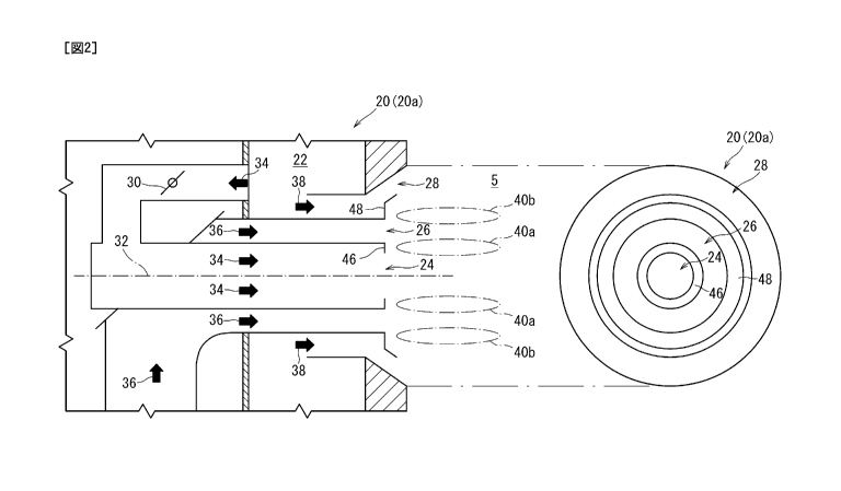
[0032] FIG. 2 is a cross-sectional view and a front view schematically
showing a burner
20 (20a) according to an embodiment of the present invention, mounted to the
furnace 5.
FIG. 3 is a block diagram for describing the function of the burner 20a. FIGs.
4 and 5 are a
cross-sectional view and a front view schematically showing a burner 20 (20b,
20c) according
to another embodiment of the present invention, mounted to the furnace 5. FIG
6 is a block
diagram for describing the function of the burner 20c. FIGs. 7 and 8 are each
a cross-
sectional view schematically showing a burner 20 (20d, 20e) according to
another
embodiment of the present invention, mounted to the furnace 5. FIG. 9 is a
cross-sectional
view and a front view schematically showing a burner 20 (200 according to
another
embodiment of the present invention, mounted to the furnace 5.
[0033] As shown in each of FIGs. 2, 4, 5, and 7 to 9, the burner 20 (20a
to 200 includes
an inner gas nozzle 24, a fuel supply nozzle 26, an outer gas nozzle 28, and a
flow-velocity-
ratio adjustment apparatus 30.
The inner gas nozzle 24 extends along an axis 32 while surrounding the axis
32, and is
capable of supplying the furnace 5 with an inner combustion oxygen containing
gas 34. The
axis 32 may be perpendicular or inclined with respect to the outer wall of the
furnace 5. The
inner combustion oxygen containing gas 34 is air, for instance. Further, for
instance, in a
.. case where oxygen combustion is applied, in which exhaust gas is
recirculated and mixed
with oxygen to be used as a combustion gas, the combustion oxygen containing
gas is a
mixed gas mainly containing carbon dioxide and oxygen.
The fuel supply nozzle 26 surrounds the inner gas nozzle 24 as seen in a
direction along
the axis 32, and is capable of supplying the furnace 5 with fluid mixture 36
of solid powder
fuel and carrier gas. The solid powder fuel is powdered coal, for instance,
and the carrier
gas is air, for instance.
[0034] The outer gas nozzle 28 surrounds the fuel supply nozzle 26 as
seen in a direction
along the axis 32, and is capable of supplying the furnace 5 with an outer
combustion oxygen
- 13 -
CA 02983989 2017-10-25
containing gas 38. The outer combustion oxygen containing gas 38 is air, for
instance.
The flow-velocity-ratio adjustment apparatus 30 is capable of adjusting the
relative flow
velocity ratio of a discharge flow velocity Fe of the inner combustion oxygen
containing gas
34 to a discharge flow velocity Fo of the outer combustion oxygen containing
gas 38.
Furthermore, the burner 20 is configured such that, at downstream of the
outlet of the
fuel supply nozzle 26, an inner flame holding region 40a and an outer flame
holding region
40b are formed on the side closer to the inner combustion oxygen containing
gas 34 and the
side closer to the outer combustion oxygen containing gas 38, respectively, of
the discharge
flow of the fluid mixture 36. The inner flame holding region 40a and the outer
flame
holding region 40b are regions in which the solid powder fuel is ignited and
combusted. The
inner flame holding region 40a and the outer flame holding region 40b are
formed
immediately downstream the outlet of the fuel supply nozzle 26.
[00351 In a case
where the above burner 20 is used, as shown in FIG 3 or 6, an inner
circulation eddies 42a are formed between the fluid mixture 36 discharged from
the fuel
supply nozzle 26 and the inner combustion oxygen containing gas 34 discharged
from the
inner gas nozzle 24. When the inner circulation eddies 42a are enhanced, the
inner
circulation eddies 42a increase the flow rate of a flow of high-temperature
gas (inner high-
temperature gas circulation flow 44a) flowing toward the fuel supply nozzle
26, which makes
it possible to stabilize ignition and flame holding in the inner flame holding
region 40a on the
side of the inner combustion oxygen containing gas 34 with heat of the inner
high-
temperature gas circulation flow 44a.
Furthermore, an outer circulation eddies 42b are formed between the fluid
mixture 36
discharged from the fuel supply nozzle 26 and the outer combustion oxygen
containing gas 38
discharged from the outer gas nozzle 28. When the outer circulation eddies 42b
are
enhanced, the outer circulation eddies 42b increase the flow rate of a flow of
high-temperature
gas (outer high-temperature gas circulation flow 44b) flowing toward the fuel
supply nozzle
26, which makes it possible to stabilize ignition and flame holding in the
outer flame holding
region 40b on the side of the outer combustion oxygen containing gas 38 with
heat of the
- 14 -
CA 02983989 2017-10-25
outer high-temperature gas circulation flow 44b.
[0036] Herein, ignition and flame holding are more easily stabilized in
the outer flame
holding region 40b than in the inner flame holding region 40a, due to
radiation from
surrounding area, for instance. Thus, the discharge flow velocity Fc of the
inner combustion
oxygen containing gas 34 and the discharge flow velocity Fo of the outer
combustion oxygen
containing gas 38 required to stabilize ignition and flame holding in the
inner flame holding
region 40a and the outer flame holding region 40b, respectively, are not
necessarily the same.
In this regard, with the above burner 20, the flow-velocity-ratio adjustment
apparatus 30
adjusts the relative flow velocity ratio of the discharge flow velocity Fe of
the inner
combustion oxygen containing gas 34 and the discharge flow velocity Fo of the
outer
combustion oxygen containing gas 38, and thereby ignition and flame holding
are stabilized
in each of the inner flame holding region 40a and the outer flame holding
region 40b.
If it is possible to adjust the relative flow velocity ratio of the discharge
flow velocity Fe
of the inner combustion oxygen containing gas 34 to the discharge flow
velocity Fo of the
outer combustion oxygen containing gas 38, ignition and flame holding can be
stabilized in
each of the inner flame holding region 40a and the outer flame holding region
40b without
providing the inner flame holding air nozzle described in W098/03819.
[0037] In some embodiments, the inner gas nozzle 24, the fuel supply
nozzle 26, and the
outer gas nozzle 28 have a multi-layered tube structure. The inner gas nozzle
24 is formed
by a tube-shaped member, and the inner combustion oxygen containing gas 34 can
flow
through the inside of the tube-shaped member. The fuel supply nozzle 26 is
formed by two
tube-shaped members surrounding the inner gas nozzle 24, and the fluid mixture
36 can flow
through the gap between the two tube-shaped members. The outer gas nozzle 28
is formed
by two tube-shaped members surrounding the fuel supply nozzle 26, and the
outer combustion
oxygen containing gas 38 can flow through the gap between the two tube-shaped
members.
[0038] The tube-shaped member (outer wall) of the inner gas nozzle 24 and
the tube-
shaped member (inner wall) on the inner side of the fuel supply nozzle 26 may
be the same
member, or may be joined to each other. Similarly, the tube-shaped member
(outer wall) on
- 15-
= CA 02983989 2017-10-25
the outer side of the fuel supply nozzle 26 and the tube-shaped member (inner
wall) on the
inner side of the outer gas nozzle 28 may be the same member, or may be joined
to each other.
In the present specification, a tube-shaped member is not limited to the
cylindrical shape
shown in FIGs. 2, 4, and 5, but includes a polygonal tube shape shown in FIG.
9.
[0039] In some embodiments, the burner 20 (20a to 200 further includes an
inner flame
holder 46 and an outer flame holder 48, as shown in each of FIGs. 2, 4, 5, and
7 to 9.
The inner flame holder 46 is disposed on an outlet section of the inner gas
nozzle 24,
and is configured to contract the flow of the inner combustion oxygen
containing gas 34.
The outer flame holder 48 is disposed on an outlet section of the outer gas
nozzle 28,
and is configured so that the flow of the outer combustion oxygen containing
gas 38 deviates
from the axis 32.
[0040] In the above burner 20, the inner flame holder 46 contracts
the inner combustion
oxygen containing gas 34 and thereby the inner circulation eddies 42a are more
easily formed
between the discharge flow of the inner combustion oxygen containing gas 34
and the
discharge flow of the fluid mixture 36. Furthermore, the outer flame holder 48
deviates the
outer combustion oxygen containing gas 38 from the axis 32 so that the outer
combustion
oxygen containing gas 38 spreads out, and thereby the outer circulation eddies
42b are more
easily formed between the discharge flow of the outer combustion oxygen
containing gas 38
and the discharge flow of the fluid mixture 36. Accordingly, it is possible to
stabilize
ignition and flame holding in each of the inner flame holding region 40a and
the outer flame
holding region 40b.
In a case where the burner 20 is further provided with the inner flame holder
46 and the
=
outer flame holder 48, the burner 20 may not necessarily include other
features for forming
each of the inner flame holding region 40a and the outer flame holding region
40b.
[0041] In some embodiments, the inner flame holder 46 comprises a plate-
shaped
member extending inward from the periphery of the outlet section of the inner
gas nozzle 24.
In some embodiments, the outer flame holder 48 comprises a plate-shaped member
extending outward from the periphery of the outlet section of the outer gas
nozzle 28.
- 16-
CA 02983989 2017-10-25
In the present specification, unless otherwise stated, the inner side refers
to the side
closer to the axis 32 and the outer side refers to the side farther from the
axis 32, with respect
to a direction intersecting with the axis 32 (radial direction).
[0042] In some embodiments, the flow-velocity-rate adjustment apparatus
30 comprises a
damper disposed in a flow passage of the inner combustion oxygen containing
gas 34. The
inlet of the flow passage of the inner combustion oxygen containing gas 34 has
an opening
into the interior of the wind box 22, and the outlet of the flow passage of
the inner combustion
oxygen containing gas 34 comprises the outlet of the inner gas nozzle 24. The
inlet of the
flow passage of the outer combustion oxygen containing gas 38 has an opening
into the
interior of the wind box 22, and the outlet of the flow passage of the outer
combustion oxygen
containing gas 38 comprises the outlet of the outer gas nozzle 28.
With this configuration, the inlets of the flow passage of the inner
combustion oxygen
containing gas 34 and the flow passage of the outer combustion oxygen
containing gas 38 are
connected to the wind box 22, which is a shared supply source of gas, and
thereby the damper
disposed in the flow passage of the inner combustion oxygen containing gas 34
can reliably
adjust the relative flow velocity ratio of the discharge flow velocity Fc of
the inner
combustion oxygen containing gas 34 to the discharge flow velocity Fo of the
outer
combustion oxygen containing gas 38, with a simple configuration.
[0043] In some embodiments, the burner 20b, 20c, 20d, 20e further
includes a plurality of
intermediate flame holders 50, as shown in each of FIGs. 4, 5, 7, and 8. The
plurality of
intermediate flame holders 50 extend between the outlet section of the inner
gas nozzle 24 and
the outlet section of the outer gas nozzle 28 so as to intersect the outlet
section of the fuel
supply nozzle 26. The plurality of intermediate flame holders 50 are disposed
separate from
one another as seen in the direction along the axis 32, and the fluid mixture
36 can be
discharged from the fuel supply nozzle 26 through the gap between the
intermediate flame
holders 50.
[0044] In the above described burner 20b, 20c, 20d, 20e, the intermediate
flame holders
50 extend so as to intersect the outlet section of the fuel supply nozzle 26,
and thereby high-
- 17-
CA 02983989 2017-10-25
temperature gas can flow along the intermediate flame holders 50 from the
outer flame
holding region 40b toward the inner flame holding region 40a. Accordingly, it
is possible to
increase the temperature of the inner flame holding region 40a, and to further
stabilize
ignition and flame holding in the inner flame holding region 40a.
In some embodiments, the intermediate flame holder 50 comprises a plate-shaped
member disposed so as to intersect the outlet section of the fuel supply
nozzle 26.
[0045] In some
embodiments, the burner 20 is configured such that the discharge flow
velocity Fe of the inner combustion oxygen containing gas 34 is higher than
the discharge
flow velocity Fo of the outer combustion oxygen containing gas 38.
In the above burner 20, the discharge flow velocity Fc of the inner combustion
oxygen
containing gas 34 is higher than the discharge flow velocity Fo of the outer
combustion
oxygen containing gas 38, and thereby the flow rate of high-temperature gas
flowing from the
outer flame holding region 40b toward the inner flame holding region 40a
increases, which
makes it possible to stabilize ignition and flame holding in the inner flame
holding region 40a
reliably.
[0046] In some
embodiments, as shown in FIGs. 5, 7, and 8, the outer gas nozzle 28
includes two or more outer gas flow passages 28a, 28b, 28c surrounding the
fuel supply
nozzle 26 as seen in a direction along the axis 32. In this case, the outer
combustion oxygen
containing gas 38 is supplied to the furnace 5 through the two or more outer
gas flow
passages 28a, 28b, 28c.
[0047] In the
above burner 20c, 20d, 20e, the outer combustion oxygen containing gas 38
is supplied through the two or more outer gas flow passages 28a, 28b, 28e,
which makes it
possible to make the flow velocity and the direction of the outer combustion
oxygen
containing gas 38 have a distribution, and thereby stabilize ignition and
flame holding even
further in each of the inner flame holding region 40a and the outer flame
holding region 40b.
For instance, the two or more outer gas flow passages 28a, 28b, 28c can be
formed by
providing one or more tube-shaped member inside the outer gas nozzle 28.
[0048] In some
embodiments, the burner 20c, 20d, 20e further includes an outer gas flow-
- 18-
CA 02983989 2017-10-25
rate regulator 52 disposed in at least one of the two or more outer gas flow
passages 28a, 28b,
28c.
In the above burner 20c, 20d, 20e, with the outer gas flow-rate regulator 52,
it is
possible to regulate the flow rate of the outer combustion oxygen containing
gas 38 flowing
.. out from the outer gas flow passage having the outer gas flow-rate
regulator 52 disposed
therein, from among the outer gas flow passages 28a, 28b, 28c. Accordingly, it
is possible to
stabilize ignition and flame holding even further in each of the inner flame
holding region 40a
and the outer flame holding region 40b.
For instance, the outer gas flow-rate regulator 52 comprises a variable vane
or a damper.
[0049] In some embodiments, as shown in FIGs. 5, 7, and 8, the two or more
outer gas
flow passages 28a, 28b, 28c include the first outer gas flow passage 28a
disposed on the side
of the fuel supply nozzle 26 as seen in a direction along the axis 32, and the
second outer gas
flow passage 28b surrounding the fuel supply nozzle 26 via the first outer gas
flow passage
28a. Furthermore, the burner 20e, 20d, 20e further comprises a second-outer-
gas guide vane
54 disposed on the outlet section of the second outer gas flow passage 28b,
and configured to
deviate a flow of the outer combustion oxygen containing gas 38 that has
passed through the
second outer gas flow passage 28b from the axis 32 gradually.
In the above burner 20c, 20d, 20e, the outer combustion oxygen containing gas
38
flowing through the second outer gas flow passage 28b enhances the outer
circulation eddies
42b, which make it possible to stabilize ignition and flame holding in the
outer flame holding
region 40b even further. As the flow of the outer combustion oxygen containing
gas 38
widens, the reduction region expands across the inner flame holding region 40a
and the outer
flame holding region 40b, which suppresses generation of NOx.
In some embodiments, the second-outer-gas guide vane 54 comprises a member
having
a truncated cone shape.
[0050] In some embodiments, as shown in FIGs. 5, 7, and 8, the burner
20c, 20d, 20e
further includes a swirl creating apparatus 56 disposed in the second outer
gas flow passage
28b.
- 19-
CA 02983989 2017-10-25
=
In the above burner 20c, 20d. 20e, swirl is created to the outer combustion
oxygen
containing gas 38 flowing through the second outer gas flow passage 28b,
thereby enhancing
the outer circulation eddies 42b, which make it possible to stabilize ignition
and flame
holding in the outer flame holding region 40b even further. Furthermore,
creating swirl to
the outer combustion oxygen containing gas 38 flowing through the second outer
gas flow
passage 28b further enhances the outer circulation eddies 42b, which further
promote
stabilization of ignition and flame holding in the outer flame holding region
40b, and further
expands the reduction region across the inner flame holding region 40a and the
outer flame
holding region 40b, thus further suppressing generation of NOx.
The swirl creating apparatus 56 may be fixed, or movable. For instance, the
swirl
creating apparatus 56 comprises a fixed vane, or a movable vane.
In some embodiments, as shown in FIG. 8, the burner 20e further includes a
swirl
creating apparatus 56 disposed in the third outer gas flow passage 28c.
[0051] FIG
10 is a diagram for describing another embodiment, where control equipment
60 is applied to the burner 20. In some embodiments, as shown in FIG 10, the
burner 20
further includes control equipment 60. The control equipment 60 is capable of
controlling
the flow-velocity-ratio adjustment apparatus 30 automatically.
In the above described burner 20, the control equipment 60 automatically
controls the
flow-velocity-ratio adjustment apparatus 30, and thereby it is possible to
stabilize ignition and
flame holding in each of the inner flame holding region 40a and the outer
flame holding
region 40b easily and reliably.
[0052] In
some embodiments, as shown in FIG 10, the burner 20 further includes
pressure sensors 62a, 62b disposed on the outlet section of the inner gas
nozzle 24 or the
outlet section of the outer gas nozzle 28. The control equipment 60 is capable
of controlling
the flow-velocity-ratio adjustment apparatus 30 on the basis of the outputs of
the pressure
sensors 62a, 62b.
In the above described burner 20, the control equipment 60 controls the flow-
velocity-
ratio adjustment apparatus 30 on the basis of the outputs of the pressure
sensors 62a, 62b, and
- 20 -
CA 02983989 2017-10-25
thereby it is possible to stabilize ignition and flame holding in each of the
inner flame holding
region 40a and the outer flame holding region 40b easily and reliably.
[0053] In some embodiments, the control equipment 60 comprises a computer.
The
control equipment 60 is capable of controlling the flow-velocity-ratio
adjustment apparatus 30
via a driving device (not shown). The driving device comprises, for instance,
an
electromagnetic actuator or a hydraulic actuator.
[0054] In some embodiments, as shown in FIGs. 5, 7, and 8, the burner 20c,
20d, 20e
further includes a concentrator 66. The concentrator 66 is disposed inside the
fuel supply
nozzle 26, and configured to form regions with a relatively high concentration
of solid powder
fuel, on the side of the inner combustion oxygen containing gas 34 and the
side of the outer
combustion oxygen containing gas 38 of a flow of the fluid mixture 36, at the
outlet section of
the fuel supply nozzle 26. That is, the concentrator 66 is configured to form
regions with a
relatively high concentration of solid powder fuel at the inner side and the
outer side of the
flow of the fluid mixture 36, compared to that in the intermediate section
between the inner
side and the outer side.
[0055] With the above burner 20c, 20d, 20e, the concentrator 66 can form
regions with a
high concentration of solid powder fuel on the side of the inner combustion
oxygen
containing gas 34 and the side of the outer combustion oxygen containing gas
38, and thereby
it is possible to stabilize ignition and flame holding even further in each of
the inner flame
holding region 40a and the outer flame holding region 40b.
In some embodiments, the concentrator 66 is a member disposed so as to
surround the
inner wall of the fuel supply nozzle 26, comprising a member disposed between
the inner wall
and the outer wall of the fuel supply nozzle 26, so as to have a gap from each
of the inner wall
and the outer wall. With such a member, it is possible to separate the fluid
mixture 36 to the
inner wall side and the outer wall side, and thereby it is possible to
distribute more solid
powder fuel, which has a greater specific weight than the carrier gas, to the
inner wall side
and the outer wall side.
For instance, the concentrator 66 comprises an annular member, and is
supported by a
- 21 -
CA 02983989 2017-10-25
support member (not shown).
[0056] FIG. 11 is
a diagram for describing a configuration of a guide member 70 that is
applicable to the burner 20. As shown in FIG. 11, the guide member 70 is
configured to
guide at least a part of the inner combustion oxygen containing gas 34 along
the surface of the
inner flame holder 46 on the side of the furnace 5.
With the above described guide member 70, a part of the inner combustion
oxygen
containing gas 34 flows along the surface of the inner flame holder 46 on the
side of the
furnace 5, and thereby it is possible to cool the inner flame holder 46, and
to suppress
adhesion of ash to the inner flame holder 46.
[0057] For instance, the guide member 70 comprises an annular flange
portion protruding
inward from the opening edge of the outlet section of the fuel supply nozzle
26. The inner
flame holder 46 comprises an annular plate, and is disposed inside the outlet
section of the
fuel supply nozzle 26. The inner flame holder 46 is supported by a support
member 71, for
instance, while protruding inward from the guide member 70. Furthermore, a gap
72 is
ensured between the inner flame holder 46 and the inner wall of the fuel
supply nozzle 26,
and a gap 73 is ensured between the inner flame holder 46 and the guide member
70. A part
of the inner combustion oxygen containing gas 34 flows through the gaps 72,
73, and can
flow along the surface of the inner flame holder 46 on the side of the furnace
5.
In the present specification, an annular shape may include a polygonal shape
and the
like, besides a circular shape.
[0058] FIG. 12 is
a diagram for describing a configuration of a guide member 76 that is
applicable to the burner 20. As shown in FIG. 12, the guide member 76 is
configured to
guide at least a part of the outer combustion oxygen containing gas 38 to flow
along the
surface of the outer flame holder 48 on the side of the furnace 5.
With the above described guide member 76, a part of the outer combustion
oxygen
containing gas 38 flows along the surface of the outer flame holder 48 on the
side of the
furnace 5, and thereby it is possible to cool the outer flame holder 48, and
to suppress
adhesion of ash to the outer flame holder 48.
- 22 -
CA 02983989 2017-10-25
[0059] For
instance, as shown in FIG 12, the guide member 76 comprises a flange
portion protruding outward from the edge of the inner wall of the outer gas
nozzle 28, at the
outlet section of the outer gas nozzle 28. The outer flame holder 48 comprises
an annular
plate, and is disposed inside the outlet section of the outer gas nozzle 28.
The outer flame
holder 48 is supported by a support member 77, for instance, while protruding
outward from
the guide member 76. Furthermore, a gap 78 is ensured between the outer flame
holder 48
and the inner wall of the outer gas nozzle 28, and a gap 79 is ensured between
the outer flame
holder 48 and the guide member 76. A part of the outer combustion oxygen
containing gas
38 flows through the gaps 78, 79, and can flow along the surface of the outer
flame holder 48
on the side of the furnace 5.
[0060] FIGs. 13
and 14 are diagrams for describing the configuration of a guide member
82 that is applicable to the burner 20. FIG 13 is a schematic front view of
the burner 20
provided with the guide member 82, and FIG. 14 is a schematic cross-sectional
view taken
along lines XIV-XIV in FIG .13.
As shown in FIG. 14, the guide member 82 is configured to guide at least a
part of the
fluid mixture 36 along the surfaces of the intermediate flame holders 50 on
the side of the
furnace 5.
With the above described guide member 82, a part of the fluid mixture 36 flows
along
the surfaces of the intermediate flame holders 50 on the side of the furnace
5, and thereby it is
possible to cool the intermediate flame holders 50, and to suppress adhesion
of ash to the
intermediate flame holders 50.
[0061] For
instance, as shown in FIGs. 13 and 14, the guide member 82 is formed by a
plate that extends intersecting the fuel supply nozzle 26, so as to cover a
part of the surfaces
of the intermediate flame holders 50 on the side of the furnace 5. The
intermediate flame
holder 50 has a slit 84 at a position covered by the guide member 82, and a
part of the fluid
mixture 36 can pass through the slit 84. The fluid mixture 36 having passed
through the slit
84 hits the guide member 82 and turns, thus flowing along the surface of the
intermediate
flame holder 50 on the side of the furnace 5, and thereby it is possible to
cool the intermediate
- 23 -
CA 02983989 2017-10-25
flame holder 50, and to suppress adhesion of ash to the intermediate flame
holder 50.
Further, as shown in FIGs. 13 and 14, if the guide member 82 covers the center
section
of the intermediate flame holders 50, the outer circulation eddies 42c are
formed on both sides
of the outer high-temperature gas circulation flow 44b, and thereby it is
possible to stabilize
ignition and flame holding even further in the outer flame holding region 40b.
[0062] In some
embodiments, as shown in FIGs. 7, and 8, the inner gas nozzle 24
includes two or more inner gas flow passages 24a, 24b surrounding the axis 32
as seen in a
direction along the axis 32. The burner 20d, 20e further comprises a flow-rate
regulator 88
capable of regulating the flow rate of the inner combustion oxygen containing
gas 34 flowing
through the innermost gas flow passage 24a closest to the axis 32 as seen in a
direction along
the axis 32, from among the two or more inner gas flow passages 24a, 24b.
For instance, the two or more inner gas flow passages 24a, 24b can be formed
by
providing one or more tube-shaped member inside the inner gas nozzle 24.
Furthermore, the
flow-rate regulator 88 may comprise a door that can open and close the opening
of the wall
forming the innermost gas flow passage 24a.
[0063] In the
above described burner 20d, 20e, the flow rate of the inner combustion
oxygen containing gas flowing through the innermost gas flow passage 24a is
regulated, and
thereby it is possible to maintain the reducing condition in the inner flame
holding region 40a
regardless of the characteristics of the solid powder fuel, and to suppress
generation of NOx.
The characteristics of the solid powder fuel include, for instance, the fuel
ratio of coal.
The fuel ratio of coal is a ratio of fixed carbon to volatile content, each of
which is a
component of coal. The higher the fuel ratio is, the less the volatile
content. If coal of a
high fuel ratio is used, the volatile content is small, and a high flow rate
of the inner
combustion oxygen containing gas 34 may weaken reduction, thus causing an
increase in the
generation amount of NOx. On the other hand, if the flow rate of the inner
combustion
oxygen containing gas 32 is simply reduced, the discharge flow velocity Fc of
the inner
combustion oxygen containing gas 34 decreases, which may make it difficult to
form the
inner flame holding region 40a.
- 24 -
=
CA 02983989 2017-10-25
[0064] In the
burner 20d, 20e, the flow-rate regulator 88 is controlled so as to reduce the
flow rate of the inner combustion oxygen containing gas 34 flowing through the
innermost
gas flow passage 24a when the fuel ratio of coal is high (a case of a high
fuel ratio), as
compared to when the fuel ratio of coal is low (a case of a mid-low fuel
ratio). Accordingly,
it is possible to reduce the flow rate (total flow rate) of the inner
combustion oxygen
containing gas 34 while maintaining the discharge flow velocity Fc of the
inner combustion
oxygen containing gas 34, and as a result, it is possible to maintain the
inner flame holding
region 40a and suppress generation of NOx.
[0065] FIG. 15 is
a flowchart of a schematic process of a method of controlling the burner
20d, 20e provided with the above described flow-rate regulator 88. As shown in
FIG 15, the
method of controlling the burner 20d, 20e includes a step S10 of obtaining a
fuel ratio, a step
S12 of determining whether the fuel ratio is high, a step S14 of setting a
small opening for the
flow-rate regulator 88 in a case of a high fuel ratio, and a step S16 of
setting a large opening
for the flow-rate regulator 88 in a case of a mid-low fuel ratio.
Whether the fuel ratio is high can be determined on the basis of whether the
fuel ratio is
greater than a threshold. For instance, a fuel ratio of coal being high (a
high fuel ratio) refers
to the fuel ratio being approximately not less than two, and a fuel ratio of
coal being low (a
mid-low fuel ratio) refers to the fuel ratio being approximately less than
two. This threshold
depends on the type of fuel and the particle size of the powdered fuel, and
may be determined
on the basis of a result of a test in a combustion test furnace or the like,
for instance.
[0066] Herein, if
the flow rate of the inner combustion oxygen containing gas 34 is
reduced when the fuel rate is high and the inner combustion oxygen containing
gas 34 and the
outer combustion oxygen containing gas 38 are supplied from the same source,
the flow rate
of the outer combustion oxygen containing gas 38 relatively increases. If the
flow rate of the
.. outer combustion oxygen containing gas 38 increases, the discharge flow
velocity Fo of the
outer combustion oxygen containing gas 38 becomes faster, thus reducing the
difference
between the discharge flow velocity Fo of the outer combustion oxygen
containing gas 38 and
the discharge flow velocity Fc of the inner combustion oxygen containing gas
34, which may
- 25 -
CA 02983989 2017-10-25
lead to a decrease in the stability of ignition and flame holding in the inner
flame holding
region 40a. This tendency is particularly strong if the intermediate flame
holders 50 are
provided and the pressure difference between the outer flame holding region
40b and the
inner flame holding region 40a is utilized to form a flow of high-temperature
gas flowing
from the outer flame holding region 40b toward the inner flame holding region
40a.
In this regard, in some embodiments, the outer gas nozzle 28 is provided with
an
adequate size of flow path area in advance, so as to optimize the discharge
flow velocity Fo of
the outer combustion oxygen containing gas 38 when the fuel ratio is high. In
a case of a
mid-low fuel ratio, the outer gas flow-rate regulator 52 reduces the flow rate
(total flow rate)
of the outer combustion oxygen containing gas 38, and the flow rate (total
flow rate) of the
inner combustion oxygen containing gas 34 is increased by an amount
corresponding to the
reduced amount of the outer combustion oxygen containing gas 38.
[0067] FIG 16 is a flowchart of a schematic process of a method of
controlling the burner
20d, 20e provided with the above described flow-rate regulator 88. The control
method
shown in FIG. 16 further includes a step of increasing the flow path area of
the outer gas
nozzle 28, that is, a step SI8 of increasing the opening of the outer gas flow-
rate regulator 52,
in a case of a high fuel ratio, and a step of reducing the flow path area of
the outer gas nozzle
28, that is, a step S20 of reducing the opening of the outer gas flow-rate
regulator 52, in a case
of a mid-low fuel ratio.
[0068] In some embodiments, as shown in FIG 7, in the burner 20d provided
with the
outer gas nozzle 28 having the first outer gas flow passage 28a and the second
outer gas flow
passage 28b, the outer gas flow-rate regulator 52 is operated so that the
reduction rate of the
flow rate of the outer combustion oxygen containing gas 38 in the second outer
gas flow
passage 28b is greater than that in the first outer gas flow passage 28a, when
reducing the
flow rate of the outer combustion oxygen containing gas 38 in a case of a mid-
low fuel ratio.
[0069] FIG. 17 is a flowchart of a schematic process of a method of
controlling the burner
20d provided with the above described flow-rate regulator 88. In the control
method shown
in FIG 17, in the step 18 of increasing the opening of the outer gas flow-rate
regulator 52, the
- 26 -
CA 02983989 2017-10-25
opening of the outer gas flow-rate regulator 52 for the second outer gas flow
passage 28b is
increased, and in the step S20 of reducing the opening of the outer gas flow-
rate regulator 52,
the opening of the outer gas flow-rate regulator 52 for the second outer gas
flow passage 28b
is reduced.
[0070] Furthermore, if the flow rate (total flow rate) of the outer
combustion oxygen
containing gas 38 is reduced in a case of a mid-low fuel ratio when the inner
combustion
oxygen containing gas 34 and the outer combustion oxygen containing gas 38 are
supplied
from the same supply source, the discharge flow velocity Fo of the outer
combustion oxygen
containing gas 38 decreases, and the outer circulation eddies 42b may weaken.
As a result,
the stability of ignition and flame holding may decrease in the outer flame
holding region 40b.
In this regard, in some embodiments, as shown in FIG. 8, in the burner 20e
provided
with the outer gas nozzle 28 having the first outer gas flow passage 28a, the
second outer gas
flow passage 28b, and the third outer gas flow passage 28c, the outer gas flow-
rate regulator
52 is operated so that the reduction rate of the flow rate of the outer
combustion oxygen
containing gas 38 in the third outer gas flow passage 28c is greater than the
reduction rate of
the flow rate of the outer combustion oxygen containing gas 38 in the second
outer gas flow
passage 28 b , when reducing the flow rate (total flow rate) of the outer
combustion oxygen
containing gas 38 in a case of a mid-low fuel ratio. In other words, in a case
where the outer
gas nozzle 28 has a plurality of outer gas flow passages, the outer gas flow-
rate regulator 52 is
operated so that the reduction rate of the flow rate of the outer combustion
oxygen containing
gas 38 is greatest in the outermost gas flow passage. Accordingly, it is
possible to suppress
reduction of the discharge flow velocity Fo of the outer combustion oxygen
containing gas 38
in a case of a mid-low fuel ratio, and to suppress weakening of the outer
circulation eddies
42b.
[0071] FIG 18 is a flowchart of a schematic process of a method of
controlling the burner
20e provided with the above described flow-rate regulator 88. In the control
method shown
in FIG. 18, in the step S 18 of increasing the opening of the outer gas flow-
rate regulator 52,
the opening of the outer gas flow-rate regulator, 52 for the third outer gas
flow passage 28c is
-27-
CA 02983989 2017-10-25
increased, and in the step S20 of reducing the opening of the outer gas flow-
rate regulator 52,
the opening of the outer gas flow-rate regulator 52 for the third outer gas
flow passage 28c is
reduced.
[0072] In some embodiments, as shown in FIGs. 19 and 20, the control
equipment 60 can
control the flow-velocity-ratio adjustment apparatus 30, the flow-rate
regulator 88, and the
outer gas flow-rate regulator 52 via a driving device (not shown), and can
perform the control
method shown in FIGs. 15 to 18 automatically. The fuel ratio of the solid
powder fuel can
be input into the control equipment 60 automatically or manually.
The flow-velocity-ratio adjustment apparatus 30, the flow-rate regulator 88,
and the
outer gas flow-rate regulator 52 may be operated manually.
[0073] In some embodiments, as shown in FIGs. 5, 7, and 8, the burner
20e, 20d, 20e
further includes an oil nozzle 90 disposed along the axis 32. The oil nozzle
90 is used when
the burner 20c, 20d, 20e is started.
[0074] In some embodiments, the solid powder fuel is powdered coal, and
as shown in
FIG 1, the powdered coal is obtained by pulverizing coal with mills 92
provided alongside the
boiler 1. The powdered coal is carried by carrier gas supplied from a fan 94,
and is supplied
to the fuel supply nozzle 26 of the burner 20. Furthermore, oxygen containing
gas is
supplied to the wind box 22 from a fan 96. The carrier gas and the oxygen
containing gas
are air, for instance. A part of the carrier gas and the oxygen containing gas
can be heated to
suitable temperature by a heater 98. The heater 98 may be assembled with the
boiler 1.
In some embodiments, an additional gas nozzle 100 for combustion is mounted to
the
furnace 5, above the burner 20, which is capable of supplying oxygen
containing gas.
[0075] Embodiments of the present invention were described in detail
above, but the
present invention is not limited thereto, and various amendments and
modifications may be
implemented.
For instance, the inner flame holder 46 only needs to be configured to
contract the flow
of the inner combustion oxygen containing gas 34, and the size, shape, and
layout of the inner
flame holder 46 is not limited to the example shown in FIG. 2 and the like.
FIG 21 is a
- 28 -
=
CA 02983989 2017-10-25
schematic configuration diagram of a burner 20g, which is a modification
example of the
burner 20c. In the burner 20g, a plate-shaped member forming the inner flame
holder 46 is
connected to the periphery of the outlet section of the inner gas nozzle 24 at
an angle other
than a right angle, for example, an obtuse angle greater than 90 degrees.
Besides, the plate-
shaped member forming the inner flame holder 46 may be integrally connected to
the plate-
shaped member forming the outer flame holder 48.
The outer flame holder 48 is disposed on the outlet section of the outer gas
nozzle 28
and only needs to be configured to deviate the flow of the outer combustion
oxygen
containing gas 38 from the axis 32, and the size, shape, and layout of the
outer flame holder
48 is not limited to the example shown in FIGs. 2 and the like. For instance,
the plate-
shaped member forming the outer flame holder 48 may be connected integrally to
the plate-
shaped member forming the inner flame holder 46, or may be connected to the
periphery of
the outlet section of the outer gas nozzle 28 at an angle other than a right
angle, for example,
an obtuse angle greater than 90 degrees. Furthermore, the outer flame holder
48 may be
formed by a plate-shaped member having an L-shaped cross section, as shown in
FIG. 21.
Description of Reference Numerals
[0076]
1 Boiler
5 Furnace
10 Combustion device
20 Burner
22 Wind box
24 Inner gas nozzle
24a, 24b Inner gas flow passage
26 Fuel supply nozzle
28 Outer gas nozzle
28a, 28b, 28c Outer gas flow passage
- 29 -
= CA 02983989 2017-10-25
30 Flow-velocity-ratio adjustment apparatus
32 Axis
34 Inner combustion oxygen containing gas
36 Fluid mixture
38 Outer combustion oxygen containing gas
40a Inner flame holding region
40b Outer flame holding region
42a Inner circulation eddy
42b Outer circulation eddy
44a Inner high-temperature gas circulation flow
44b Outer high-temperature gas circulation flow
46 Inner flame holder
48 Outer flame holder
50 Intermediate flame holder
52 Outer gas flow-rate regulator
54 Second-outer-gas guide vane
56 Swirl creating apparatus
60 Control equipment
62a, 62b Pressure sensor
64 Driving device
66 Concentrator
70 Guide member
71 Support member
72 Gap
73 Gap
76 Guide member
77 Support member
78 Gap
- 30 -
CA 02983989 2017-10-25
79 Gap
82 Guide member
83 Support member
84 Gap
85 Gap
88 Flow-rate regulator
90 Oil nozzle
92 Mill
94 Fan
96 Fan
98 Heater
100 Additional combustion gas nozzle
-31 -