Note: Descriptions are shown in the official language in which they were submitted.
1
FUEL CELL VEHICLE
CROSS-REFERENCE TO RELATED APPLICATIONS
[0001]
The present application claims priority based on Japanese patent
application No. 2016-214855 filed on November 2, 2016.
BACKGROUND
FIELD
[0002]
The present disclosure relates to a fuel cell vehicle equipped with a
fuel cell.
RELATED ART
[0003]
In a proposed configuration of a fuel cell vehicle, a fuel cell module
including a fuel cell stack is placed in a placement chamber provided in
front of a passenger compartment, and a tank for storing hydrogen gas is
placed in a hydrogen tank chamber provided under a floor of the passenger
compartment (as described in JP 2015-231319A). In the fuel cell vehicle of
JP 2015-231319A, the fuel cell stack is mounted to a suspension member via
a mounting component. This mounting component is destroyed in the
event of a collision, so as to allow the fuel cell stack to be moved into a
retreat space below the hydrogen tank chamber and thereby avoid a
collision between the fuel cell stack and the tank.
[0004]
In the fuel cell vehicle of JP2015-231319A, the fuel cell stack and the
tank are arranged to overlap with each other when being viewed in the
horizontal direction. When the fuel cell stack moves in a horizontal
direction by the impact of a collision or when the tank moves forward by the
inertia force without destruction of the mounting component in the event of
a collision, the fuel cell stack is likely to collide with the tank and damage
the tank. This problem is not characteristic of the fuel cell stack but may
arise in a configuration that any other component of the fuel cell module is
arranged to overlap with the tank when being viewed in the horizontal
direction. There is accordingly a need for a technique that suppresses a
collision between the fuel cell module and the tank in the event of a
collision
CA 2984040 2017-10-27
2
of the fuel cell vehicle.
SUMMARY
[0005]
(1) According to one aspect of the disclosure, there is provided a fuel
cell vehicle. This fuel cell vehicle comprises a fuel cell module configured
to
include a fuel cell stack, a tank configured to store a gas that is supplied
to
the fuel cell stack, a fuel cell placement chamber configured to place the
fuel
cell module therein and a tank placement chamber formed on a rear side of
the fuel cell placement chamber in a vehicle longitudinal direction of the
fuel cell vehicle under a floor of the fuel cell vehicle and configured to
place
the tank therein. The fuel cell module is placed vertically above the tank
such as not to overlap with the tank when being viewed in the vehicle
longitudinal direction. In the fuel cell vehicle of this aspect, the fuel cell
module is placed vertically above the tank such as not to overlap with the
tank when being viewed in the vehicle longitudinal direction. This
configuration suppresses a collision between the fuel cell module and the
tank even when the fuel cell module moves along the vehicle longitudinal
direction toward the tank or when the tank moves along the vehicle
longitudinal direction toward the fuel cell module by the inertia force in the
event of a collision of the fuel cell vehicle.
[0006]
(2) In the fuel cell vehicle of the above aspect, the fuel cell module
further includes a plate-like supporting frame configured to support the fuel
cell stack from below, wherein the supporting frame includes a first recess
that is formed in a region including part of a rear end of the supporting
frame in the vehicle longitudinal direction and corresponding to an upper
portion of the tank in a vertical direction when being viewed in the vehicle
longitudinal direction and that is open at least on a vertically lower side
and
a rear side in the vehicle longitudinal direction. In the fuel cell vehicle of
this aspect, the first recess is formed in the supporting frame. Even when
the fuel cell module and the tank move relative to each other such that the
upper portion of the tank in the vertical direction approaches toward the
first recess in the event of a collision of the fuel cell vehicle, this
configuration causes the upper portion of the tank in the vertical direction
to be located (placed) below the first recess and thereby suppresses a
CA 2984040 2017-10-27
3
collision between the fuel cell module and the tank. This configuration
suppresses a collision between the fuel cell module and the tank in the event
of a collision of the fuel cell vehicle even when the fuel cell module is
placed
at the lower position in the vertical direction, compared with a configuration
without the first recess formed in the supporting frame. The configuration
that enables the fuel cell module to be placed at the lower position in the
vertical direction may reduce the height of the fuel cell placement chamber
to achieve downsizing of the fuel cell vehicle or may increase the space for
placing the components other than the fuel cell module in the fuel cell
placement chamber while keeping the height of the fuel cell placement
chamber unchanged. The configuration that enables the fuel cell module to
be placed at the lower position in the vertical direction can lower the
overall
center of gravity of the components placed in the fuel cell placement
chamber and improve the driving stability.
[0007]
(3) In the fuel cell vehicle of the above aspect, the first recess is
configured as a cutout formed in a thickness direction of the supporting
frame. In the fuel cell vehicle of this aspect, the first recess is configured
as
a cutout. The first recess of this configuration more reliably suppresses a
collision between the supporting frame and the tank in the event of a
collision of the fuel cell vehicle, compared with the first recess configured
not as a cutout. This accordingly enables the fuel cell stack to be placed at
the lower position in the vertical direction.
[0008]
(4) In the fuel cell vehicle of the above aspect, the fuel cell stack
comprises a plurality of stacked unit cells and an end plate placed on a rear
side end in the vehicle longitudinal direction along a stacking direction of
the plurality of unit cells, wherein the end plate includes a second recess
that is formed in a region including part of a rear end of the end plate in
the
vehicle longitudinal direction and corresponding to an upper portion of the
tank in a vertical direction when being viewed in the vehicle longitudinal
direction and that is open at least on a vertically lower side and a rear side
in the vehicle longitudinal direction. In the fuel cell vehicle of this
aspect,
the second recess is formed in the end plate. Even when the fuel cell
module and the tank move relative to each other such that the upper portion
of the tank in the vertical direction approaches toward the second recess in
CA 2984040 2017-10-27
4
the event of a collision of the fuel cell vehicle, this configuration causes
the
upper portion of the tank to be located (placed) below the second recess and
thereby suppresses a collision between the fuel cell module and the tank.
This configuration suppresses a collision between the end plate and the tank
in the event of a collision of the fuel cell vehicle even when the end plate
is
placed at the lower position in the vertical direction, compared with a
configuration without the second recess formed in the end plate. The
configuration that enables the end plate to be placed at the lower position in
the vertical direction may reduce the height of the fuel cell placement
chamber to achieve downsizing of the fuel cell vehicle. The configuration
that enables the end plate to be placed at the lower position in the vertical
direction can lower the overall center of gravity of the components placed in
the fuel cell placement chamber and improve the driving stability.
[0009]
(5) The fuel cell vehicle of the above aspect further comprises a case
configured to place the fuel cell stack therein with the end plate exposed and
joined with the end plate at a tank-side end face of the case by a fastening
member provided to pass through the end plate in a thickness direction,
wherein a lowermost portion in the vertical direction of the end plate is
located in the vertical direction below a lowermost portion in the vertical
direction of the case, and the second recess of the end plate is formed
between two through holes provided in the end plate to respectively receive
fastening members that are adjacent to each other in a vehicle width
direction of the fuel cell vehicle. In the fuel cell vehicle of this aspect,
the
second recess is formed between the two through holes that are arranged
adjacent to each other in the vehicle width direction to receive the fastening
members respectively. This configuration suppresses reduction of the
joining force of the end plate with the case, while providing the second
recess.
[0010]
(6) In the fuel cell vehicle of the above aspect, the second recess is
configured as a cutout formed in a thickness direction of the end plate. In
the fuel cell vehicle of this aspect, the second recess is configured as a
cutout. The second recess of this configuration more reliably suppresses a
collision between the end plate and the tank in the event of a collision of
the
fuel cell vehicle, compared with the second recess configured not as a cutout.
CA 2984040 2017-10-27
5
This accordingly enables the fuel cell stack including the end plate to be
placed at the lower position in the vertical direction.
[0011]
(7) In the fuel cell vehicle of the above aspect, the fuel cell stack is
arranged to be inclined downward toward the tank in the vehicle
longitudinal direction. In the fuel cell vehicle of this aspect, the fuel cell
stack is arranged to be inclined downward toward the tank in the vehicle
longitudinal direction. This configuration causes water in the fuel cell
stack to be moved toward the tank by use of the gravity and to be readily
discharged from the fuel cell stack.
[0012]
(8) In the fuel cell vehicle of the above aspect, the tank placement
chamber is configured to place the tank therein such that a longitudinal
direction of the tank is aligned with the vehicle longitudinal direction. In
the fuel cell vehicle of this aspect, the tank placement chamber is configured
to place the tank therein such that the longitudinal direction of the tank is
aligned with the vehicle longitudinal direction. This configuration enables
a larger tank to be placed in the tank placement chamber, compared with a
configuration that places the tank such that the longitudinal direction of the
tank is aligned with the vehicle width direction.
[0013]
The disclosure may be implemented by various aspects other than
those described above, for example, a manufacturing method of the fuel cell
vehicle, a method of arranging a fuel cell module and a tank in the fuel cell
vehicle, a fuel cell module, a supporting frame for a fuel cell stack, and an
end plate for a fuel cell stack.
BRIEF DESCRIPTION OF DRAWINGS
[0014]
Fig. 1 is a sectional view illustrating the schematic configuration of a
fuel cell vehicle according to one embodiment of the disclosure;
Fig. 2 is a block diagram illustrating the schematic configuration of
a fuel cell system mounted on the fuel cell vehicle;
Fig. 3 is a sectional view illustrating the schematic configuration of a
fuel cell module;
Fig. 4 is a perspective view illustrating the configuration of a case
CA 2984040 2017-10-27
6
and a supporting frame;
Fig. 5 is a perspective view illustrating the schematic configuration
of a fuel cell stack;
Fig. 6 is a front view illustrating an end plate;
Fig. 7 is a sectional view illustrating the motions of the fuel cell
stack, the supporting frame, and a tank in the event of a collision;
Fig. 8 is a perspective view illustrating the schematic configuration
of a supporting frame according to a second embodiment;
Fig. 9 is a sectional view illustrating the schematic configuration of a
fuel cell vehicle according to a third embodiment; and
Fig. 10 is a perspective view illustrating the schematic configuration
of a supporting frame according to the third embodiment.
DESCRIPTION OF EMBODIMENTS
[00151
A. First Embodiment
Al. General Configuration of Vehicle
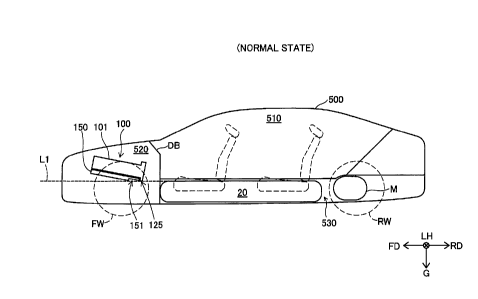
Fig. 1 is a sectional view illustrating the schematic configuration of a
fuel cell vehicle 500 according to one embodiment of the disclosure. Fig. 1
illustrates a section along a forward direction FD and a rearward direction
RD of the vehicle at the middle position in a vehicle width direction LH of
the fuel cell vehicle 500 in a normal state without a collision. Hereinafter,
the forward direction FD and the rearward direction RD are collectively
referred as "vehicle longitudinal direction". The fuel cell vehicle 500 is
equipped with a fuel cell module 100 as a power source and is configured
such that rear wheels RW are driven by driving a motor M as a driving
source. The direction of gravity, i.e., a vertically downward direction G, is
shown in Fig. 1, in addition to the vehicle width direction LH, the forward
direction FD, and the rearward direction RD. The reference signs and
arrows indicating the respective directions in Fig. 1 correspond to the
reference signs and arrows indicating the respective directions in the other
drawings.
[00161
The fuel cell vehicle 500 is configured to form a passenger
compartment 510, a fuel cell placement chamber 520, and a tank placement
chamber 530.
CA 2984040 2017-10-27
7
[0017]
The passenger compartment 510 is a room for passengers and is
equipped with a plurality of seats as shown by broken lines in Fig. 1. The
passenger compartment 510 is practically located in a region between a pair
of front wheels FW and a pair of rare wheels RW.
[0018]
The fuel cell placement chamber 520 is configured to place at least
part of components of a fuel cell system (fuel cell system 200 described
later)
including the fuel cell module 100 therein. The fuel cell module 100
includes a fuel cell stack 101 and a supporting frame 150. The fuel cell
module 100 further includes a case (case 130 described later) as described
below, although the case is omitted from the illustration of Fig. 1. The fuel
cell stack 101 has a stacked body including a plurality of stacked unit cells
(unit cells 11 described later). The supporting frame 150 is a plate-like
member configured to support the fuel cell stack 101 from below. The
detailed configuration of the fuel cell module 100 including the fuel cell
stack 101 and the supporting frame 150 will be described later. The fuel
cell placement chamber 520 is located on the forward direction FD-side of
the passenger compartment 510. The passenger compartment 510 and the
fuel cell placement chamber 520 are separated from each other by a
dashboard DB. The dashboard DB is a plate-like member configured such
that an upper side portion is bent forward. A lower side portion of the
dashboard DB is arranged to be approximately parallel to the vertical
direction.
[0019]
The tank placement chamber 530 is configured to place a tank 20 for
storing hydrogen gas therein. The tank placement chamber 530 is formed
on the rearward direction RD-side of the fuel cell placement chamber 520
under a floor of the fuel cell vehicle 500. The tank placement chamber 530
is also formed along with the vehicle longitudinal direction at the
approximate center in the vehicle width direction LH. The tank placement
chamber 530 has a ceiling portion that is formed by a floor panel of the
passenger compartment 510. Part of the floor of the passenger
compartment 510 corresponding to the tank placement chamber 530 is
protruded vertically upward from the remaining part of the floor. The tank
placement chamber 530 has a structure similar to the center tunnel where a
CA 2984040 2017-10-27
8
driveshaft is placed in a vehicle equipped with an engine. The tank
placement chamber 530 is configured to place a wire harness and the like
(not shown) therein, in addition to the tank 20.
[0020]
As shown in Fig. 1, the fuel cell module 100 placed in the fuel cell
placement chamber 520 is arranged to be inclined downward toward the
tank 20 in the vehicle longitudinal direction. In other words, the fuel cell
module 100 is arranged to be inclined to the horizontal direction such as to
be placed at the lower position toward the rearward direction RD. The
reason for such inclined arrangement of the fuel cell module 100 is to cause
water in the fuel cell stack 101 to be collected in the rearward direction RD
by use of the gravity and to be readily discharged from the fuel cell stack
101.
[0021]
As illustrated, a first recess 151 is formed in a vertically lower
surface of the supporting frame 150. A second recess 125 is formed in an
end plate (end plate 120 described later) included in the fuel cell stack 101.
The detailed structures of the first recess 151 and the second recess 125 will
be described later.
[0022]
The fuel cell module 100 is placed vertically above the tank 20 such
as not to overlap with the tank 20 when being viewed in the vehicle
longitudinal direction. In other words, any part of a lowermost surface of
the fuel cell module 100 is located vertically above a corresponding part in
the vertical direction of an uppermost surface of the tank 20 when being
viewed in the vehicle longitudinal direction. The above state that "the fuel
cell module 100 is placed vertically above the tank 20" means that the
uppermost portion in the vertical direction of the fuel cell module 100 is
arranged vertically above the uppermost portion in the vertical direction of
the tank 20. In Fig. 1, a virtual line L1 that passes through the uppermost
portion in the vertical direction of the tank 20 and is parallel to a
horizontal
plane is drawn by the broken line. This virtual line Li corresponds to a
trajectory of the uppermost portion of the tank 20 assumed in the event of a
collision. The uppermost portion of the fuel cell module 100 is located
vertically above this virtual line Li.
[0023]
CA 2984040 2017-10-27
9
A2. Configuration of Fuel Cell System
Fig. 2 is a block diagram illustrating the schematic configuration of
a fuel cell system 200 mounted on the fuel cell vehicle 500. The fuel cell
system 200 includes a gas-liquid separator 29, the tank 20, an air
compressor 30, a shut-off valve 24, an injector 25, an exhaust drainage valve
26, a circulating pump 27, a three-way valve 33, a pressure regulating valve
34, a fuel gas supply path 21, a fuel gas circulation path 22, a fuel gas
discharge path 23, an oxidant gas supply path 31, an oxidant gas discharge
path 32, a bypass flow path 35 and a DC-DC converter 210, in addition to
the fuel cell stack 101 described above. The fuel cell system 200 further
includes a mechanism configured to circulate a cooling medium through the
fuel cell stack 101, although not being illustrated.
[0024]
The fuel cell stack 101 includes a plurality of stacked unit cells 11
and a pair of end plates 110 and 120 provided at the respective ends in the
stacking direction. Each unit cell 11 is a polymer electrolyte fuel cell
configured to generate electric power by an electrochemical reaction
between a fuel gas and an oxidant gas that are respectively supplied to an
anode-side catalyst electrode layer and to a cathode-side catalyst electrode
layer provided across a solid polymer electrolyte membrane. According to
the first embodiment, the fuel gas is hydrogen gas, and the oxidant gas is
the air. The fuel cell stack 101 is arranged such that the end plate 110 is
located on the forward direction FD-side and the end plate 120 is located on
the rearward direction RD-side. The catalyst electrode layer is configured
to include carbon particles with a catalyst such as platinum (Pt) supported
thereon and an electrolyte. Gas diffusion layers made of a porous material
are placed outside of the catalyst electrode layers on the respective
electrode
sides in the unit cell 11. The porous material may be, for example, porous
carbon such as carbon paper or carbon cloth or porous metal such as metal
mesh or foamed metal. Manifolds (not shown) for the fuel gas, the oxidant
gas and the cooling medium are formed along a stacking direction SD of the
unit cells 11 inside of the fuel cell stack 101. The unit cell 11 may not be
necessarily limited to the polymer electrolyte fuel cell but may be any other
type of fuel cell such as solid oxide fuel cell.
[0025]
The pair of end plates 110 and 120 serve to place the stacked body
CA 2984040 2017-10-27
10
including the plurality of unit cells 11 therebetween. In the pair of end
plates 110 and 120, the end plate 120 has a function of providing flow paths
for supplying and discharging the fuel gas, the oxidant gas, and the cooling
medium to and from the manifolds formed in the fuel cell stack 101. The
end plate 110, on the other hand, does not have such a function. Both the
end plate 110 and the end plate 120 have approximately plate-like external
shapes with their thickness directions aligned with the stacking direction
SD.
[0026]
The tank 20 is configured to store high-pressure hydrogen and
supply hydrogen gas as the fuel gas to the fuel cell stack 101 through the
fuel gas supply path 21. As shown in Fig. 1, the tank 20 has an
approximately cylindrical external shape and is placed in the tank
placement chamber 530 such that its longitudinal direction is aligned with
the vehicle longitudinal direction. The circulating pump 27 is placed in the
fuel gas circulation path 22 and is configured to feed the fuel gas (fuel gas
after separation of water) discharged from the gas-liquid separator 29 to the
fuel gas supply path 21. The shut-off valve 24 is placed in the vicinity of a
fuel gas discharge port of the tank 20 and is configured to change over
between the supply and the stop of hydrogen gas from the tank 20. The
injector 25 is placed in the fuel gas supply path 21 and is configured to
regulate the supply amount (flow rate) and the pressure of hydrogen gas
supplied to the fuel cell stack 101. The gas-liquid separator 29 is connected
with the fuel gas discharge manifold in the fuel cell stack 101 and is
configured to separate and discharge water included in an off-gas
discharged from this manifold and to discharge a gas (fuel gas) after
separation of water. The exhaust drainage valve 26 is placed in the fuel
gas discharge path 23 and is configured to change over between the
discharge and the stop of water and the off-gas from the gas-liquid separator
29. The air compressor 30 is configured to supply the air as the oxidant gas
to the fuel cell stack 101. The three-way valve 33 is placed in the oxidant
gas supply path 31 and is configured to regulate the amount of the air to be
supplied to the oxidant gas supply path 31 and the amount of the air to be
supplied to the bypass flow path 35 in the total amount of the air supplied
from the air compressor 30. The pressure regulating valve 34 is placed in
the oxidant gas discharge path 32 and is configured to regulate the pressure
CA 2984040 2017-10-27
11
on the cathode discharge side (back pressure) in the fuel cell stack 101.
[0027]
The following describes the flow of the fuel gas in the fuel cell system
200. The hydrogen gas fed from the tank 20 is supplied to the fuel cell
stack 101 through the fuel gas supply path 21. The off-gas (anode-side off-
gas) discharged from the fuel cell stack 101 is supplied to the gas-liquid
separator 29, which separates at least part of water included in the off-gas.
The off-gas after separation of water (i.e., fuel gas) is recirculated to the
fuel
gas supply path 21 through the fuel gas circulation path 22 and the
circulating pump 27 and is again supplied to the fuel cell stack 101. Part of
the off-gas supplied to the gas-liquid separator 29 is discharged from the
gas-liquid separator 29 to the fuel gas discharge path 23 through the
exhaust drainage valve 26, in addition to the water separated from the off-
gas. The fuel gas discharge path 23 is connected with the oxidant gas
discharge path 32, and the water and the anode-side off-gas discharged to
the fuel gas discharge path 23 are discharged to the atmosphere through the
oxidant gas discharge path 32, along with the water and the cathode-side
off-gas discharged from the fuel cell stack 101. The fuel gas discharge path
23 communicates with the oxidant gas discharge path 32 that is open to the
atmosphere, while a back pressure higher than the atmospheric pressure is
applied to inside of the gas-liquid separator 29. There is accordingly a
pressure difference across the exhaust drainage valve 26. When the
exhaust drainage valve 26 is opened, the off-gas is discharged from the gas-
liquid separator 29 to the fuel gas discharge path 23 by the above pressure
difference.
[0028]
The following describes the flow of the oxidant gas in the fuel cell
system 200. The air (compressed air) fed from the air compressor 30 is
supplied to the fuel cell stack 101 through the oxidant gas supply path 31.
The amount of the air supplied to the fuel cell stack 101 is regulated by
adjusting the position of the three-way valve 33. The off-gas (cathode-side
off-gas) and the water discharged from the fuel cell stack 101 are discharged
to the oxidant gas discharge path 32 via the pressure regulating valve 34.
The oxidant gas discharge path 32 is connected with the fuel gas discharge
path 23 as described above and is also connected with the bypass flow path
35. The cathode-side off-gas discharged from the fuel cell stack 101 is
CA 2984040 2017-10-27
12
discharged to the atmosphere, along with the anode-side off-gas and the
water discharged through the fuel gas discharge path 23 and the air
discharged through the bypass flow path 35.
[0029]
The fuel cell stack 101 is arranged to be inclined to the horizontal
direction such as to be placed at the lower position toward the rearward
direction RD as described above, so that the end plate 120 is located at the
lowermost position in the vertically downward direction G in the fuel cell
stack 101. This configuration causes the water in the fuel cell stack 101 to
move through the respective manifolds toward the end plate 120 by the
gravity and accelerates drainage of water from the fuel cell stack 101.
[0030]
A pair of current collectors 103F and 103 R in the fuel cell stack 101
are electrically connected with the DC-DC converter 210. The DC-DC
converter 210 is electrically connected with the motor M and is configured to
boost the output voltage of the fuel cell stack 101 and supply the boosted
voltage to the motor M.
[00311
The operations of the exhaust drainage valve 26, the air compressor
30, the circulation pump 27, and the other respective valves described above
are controlled by a controller (not shown). This controller may be
configured to include a ROM (Read Only Memory) that stores control
programs, a CPU (Central Processing Unit) that reads out the control
programs from the ROM and executes the control programs, and a RAM
(Random Access Memory) that is used as a work area of the CPU.
[00321
A3. Configuration of Fuel Cell Module
Fig. 3 is a sectional view illustrating the schematic configuration of
the fuel cell module 100. Fig. 3 illustrates a section of the fuel cell module
100 at a position similar to that of Fig. 1. The fuel cell module 100 includes
a case 130, in addition to the fuel cell stack 101 described above and the
supporting frame 150.
[0033]
The fuel cell stack 101 is configured to include a pair of insulating
plates 102F and 102R, in addition to the plurality of stacked unit cells 11,
the pair of end plates 110 and 120 and the pair of current collectors 103F
CA 2984040 2017-10-27
13
and 103R described above. The pair of current collectors 103F and 103R
serve as the overall electrodes. The current collector 103F is placed on the
forward direction FD-side of the forward-most unit cell 11 among the
plurality of unit cells 11 to adjoin to this forward-most unit cell 11. The
current collector 103R is placed on the rearward direction RD-side of the
rearward-most unit cell 11 among the plurality of unit cells 11 to adjoin to
this rearward-most unit cell 11. The pair of insulating plates 102F and
102F are plate-like members made of an insulating material. The
insulating plate 102F is placed between the end plate 110 and the current
collector 103F to suppress the electrical connection between the end plate
110 and the current collector 103F. The insulating plate 102R is placed
between the end plate 120 and the current collector 103R to suppress the
electrical connection between the end plate 120 and the current collector
103R.
[0034]
The case 130 is configured to place the remaining part of the fuel cell
stack 101 other than the end plate 120 therein. In other words, the fuel
cell stack 101 with the end plate 120 exposed is placed in the case 130.
According to the first embodiment, the case 130 is made of aluminum (Al).
The material of the case 130 is, however, not limited to aluminum but may
be stainless steel (SUS), titanium (Ti) or any of metal alloys thereof. The
material of the case 130 is also not limited to the metal but may be a resin
or the like. The lowermost portion of the end plate 120 is located below the
lowermost portion of the case 130 in the vertically downward direction G as
shown in Fig. 3.
[0035]
Fig. 4 is a perspective view illustrating the configuration of the case
130 and the supporting frame 150. In Fig. 4, the upper side shows an
external perspective view of the case 130, and the lower side shows an
external perspective view of the supporting frame 150.
[0036]
As shown in Fig. 4, the case 130 has a tubular external shape that is
open at an end on the rearward direction RD-side and is hollow inside. The
remaining part of the fuel cell stack 101 other than the end plate 120 is
placed in an inner space An of the case 130. Fixing elements 131 are
formed at four corners on the bottom of the case 130. The fixing element
CA 2984040 2017-10-27
14
131 is protruded in the horizontal direction and has a through hole that is
formed at the center portion to pass through in the thickness direction. A
flange portion 132 that is folded upward is formed at a rearward direction
RD-side end of the case 130. A plurality of threaded holes 133 extended in
the thickness direction are formed in the flange portion 132. A plurality of
threaded holes 134 extended in the stacking direction are formed in an end
face (portion including the opening) on the rearward direction RD-side of the
case 130. These threaded holes 133 and 134 are formed as female threads.
[0037]
As shown in Fig. 4, the supporting frame 150 has a plate-like
external shape and has threaded holes 152 that are formed at four corners.
These threaded holes 152 are formed at the positions corresponding to the
through holes of the four fixing elements 131 of the case 130 described
above. The respective threaded holes 152 are formed as female threads.
The case 130 is placed on an upper face of the supporting frame 150 and is
joined with the supporting frame 150 by screwing male screws (not shown)
inserted via the through holes of the fixing elements 131 with the threaded
holes 152 of the supporting frame 150. A plurality of threaded holes 153
are formed in an end face on the rearward direction RD-side of the
supporting frame 150. The plurality of these threaded holes 153 are used
to join the supporting frame 150 with the end plate 120 as described later.
The supporting frame 150 is provided with a mount portion (not shown) and
is attached to a suspension member (not shown) by this mount portion.
This suspension member is placed in the fuel cell placement chamber 520
and is joined with a body frame (not shown). According to a modification,
the supporting frame 150 may be directly attached to the body frame (not
shown) without using the suspension member.
[0038]
The first recess 151 is formed on a vertically downward direction G-
side surface of the supporting frame 150. The first recess 151 is formed in
the supporting frame 150 in a region corresponding to the upper portion of
the tank 20 in the vertical direction when being viewed from the vehicle
longitudinal direction. In other words, the first recess 151 is arranged on
the rearward direction RD-side end and at the approximate center in the
vehicle width direction LH in the vertically downward direction G-side
surface of the supporting frame 150. The first recess 151 is open at least in
CA 2984040 2017-10-27
15
the vertically downward direction G and in the rearward direction RD and
has a smaller thickness than the other part of the supporting frame 150.
The first recess 151, however, has a non-zero thickness and is thus not
formed as a cutout. The first recess 151 is unrecognizable when the
supporting frame 150 is viewed from above. The non-zero thickness of the
first recess 151 suppresses reduction in rigidity of the supporting frame 150.
According to the first embodiment, the planar view shape of the first recess
151 or more specifically the planar view shape of the first recess 151 viewed
from below is an approximately rectangular shape. The first recess 151 is
accordingly formed as a cavity in an approximately rectangular
parallelepiped shape. The shape of the first recess 151 viewed in the
forward direction FD is also an approximately rectangular shape.
[0039]
Fig. 5 is a perspective view illustrating the schematic configuration
of the fuel cell stack 101. Fig. 6 is a front view illustrating the end plate
120. Fig. 6 shows a front view of the end plate 120 viewed in the forward
direction FD. Screws (screws 160 described later) used to attach the end
plate 120 to the case 130 and the supporting frame 150 are omitted from the
illustration of Fig. 6. In Fig. 6, the outline of the tank 20 viewed in the
forward direction FD is shown by the broken line.
[0040]
As shown in Fig. 6, a plurality of threaded holes are formed in the
vicinity of the outer edge of the end plate 120. The plurality of these
threaded holes include three threaded holes 122a, 122b, and 122c arrayed in
a location near to a vertically lower end face of the end plate 120. The two
threaded holes 122a and 122b are arranged to adjoin to each other. The
threaded hole 122c is arranged on the opposite side to the threaded hole
122a across the threaded hole 122b to adjoin to the threaded hole 122b.
The two threaded holes 122a and 122b are located in an approximate center
portion in the vehicle width direction LH of the end plate 120.
[0041]
As shown in Fig. 6, the second recess 125 is formed as a cutout
between the two threaded holes 122a and 122b. The second recess 125 is
open at least in the vertically downward direction G and in the rearward
direction RD. The second recess 125 is formed in a region of the end plate
120 that includes a rearward direction RD-side end of the end plate 120 and
CA 2984040 2017-10-27
16
corresponds to an upper portion 20a of the tank 20 in the vertical direction
when being viewed in the vehicle longitudinal direction. A wall surface
122W of the end plate 120 facing the second recess 125 has an arc planar
view shape. This shape of the wall surface 122W is approximately identical
with the planar view shape of part of an outer circumferential face of the
upper portion 20a of the tank 20. In other words, the second recess 125 is
formed such that the shape of the wall surface 122W conforms to the planar
view shape of part of the outer circumferential face of the upper portion 20a
of the tank 20. The wall surface 122W is, however, located slightly
vertically above the outer circumferential face of the upper portion 20a of
the tank 20. In other words, any part of the wall surface 122W is located
slightly vertically above a corresponding part in the vertical direction on
the
outer circumferential face of the tank 20 when being viewed in the vehicle
longitudinal direction. Accordingly, the wall surface 122W does not overlap
with the upper portion 20a of the tank 20 when being viewed in the vehicle
longitudinal direction.
[0042]
According to the first embodiment, the distance between the two
threaded holes 122a and 122b is longer than the distance of any two other
adjacent threaded holes among the plurality of threaded holes arrayed in
the location near to the vertically lower end face of the end plate 120. For
example, the distance between the two threaded holes 122a and 122b is
longer than the distance between the two threaded holes 122b and 122c.
This configuration of the first embodiment increases the size of the second
recess 125 by increasing the distance between the two threaded holes 122a
and 122b arranged to adjoin to each other across a portion where the second
recess 125 is formed.
[0043]
As shown in Fig. 5, screws 160 are respectively inserted in the
plurality of threaded holes formed in the vicinity of the outer edge of the
end
plate 120, The screws 160 are inserted into the plurality of threaded holes
133 and the plurality of threaded holes 134 formed in the case 130 shown in
Fig. 4 and into the plurality of threaded holes 153 formed in the supporting
frame 150 shown in Fig. 4 via the threaded holes formed in the end plate
120 and are screwed with the female threads provided in these threaded
holes 133, 134 and 153. The end plate 120 is accordingly joined with the
CA 2984040 2017-10-27
17
case 130 and with the supporting frame 150. The screw 160 corresponds to
the subordinate concept of the clamping member in the claims.
[0044]
A4. Motions in the Event of Collision
Fig. 7 is a sectional view illustrating the motions of the fuel cell
stack 101, the supporting frame 150, and the tank 20 in the event of a
collision. Fig. 7 shows a front portion of the fuel cell vehicle 500 in the
event of a front collision with omission of a rear portion of the fuel cell
vehicle 500. Fig. 7 shows a section of the fuel cell vehicle 500 at a position
similar to that of Fig. 1. For convenience of illustration, the front wheels
FW are omitted from the illustration of Fig. 7.
[00451
When the fuel cell vehicle 500 comes into collision with a collision
object 900 ahead of the vehicle, the fuel cell module 100 collides with the
collision object 900 via the vehicle body (for example, hood and radiator
grille) to stop its forward move. At this time, the tank 20 has not yet
collided with the collision object 900 via the vehicle body and other
components and accordingly tends to move forward by the inertia force.
The tank 20 is thrusted in the forward direction FD from the tank
placement chamber 530. The fuel cell module 100 is, however, placed
vertically above the tank 20 such as not to overlap with the tank 20 when
being viewed in the vehicle longitudinal direction as described above. Even
when the tank 20 is thrusted in the forward direction FD, the fuel cell
module 100 accordingly does not collide with the tank 20. This
configuration thus suppresses the tank 20 from being damaged in the event
of a collision.
[0046]
The example of collision shown in Fig. 7 illustrates an example that
stops the fuel cell module 100 from moving forward while moving the tank
20 in the forward direction FD. The configuration of the embodiment
similarly suppresses the tank 20 from being damaged in the case of another
example of collision. For example, when the fuel cell module 100 moves in
the forward direction FD at a speed lower than the speed of the tank 20 that
moves forward or when the fuel cell module 100 moves in the rearward
direction RD as the reaction of a collision of the fuel cell module 100 with
the vehicle body, the fuel cell module 100 does not collide with the tank 20.
CA 2984040 2017-10-27
18
This accordingly suppresses the tank 20 from being damaged. Even when
at least one of the fuel cell module 100 and the tank 20 is moved by a
collision of the fuel cell vehicle 500 and the fuel cell module 100 and the
tank 20 come close to each other, the configuration of the embodiment
suppresses a collision between the fuel cell module 100 and the tank 20 and
thereby suppresses the tank 20 from being damaged.
[0047]
In the fuel cell vehicle 500 of the first embodiment described above,
the fuel cell module 100 is placed vertically above the tank 20 such as not to
overlap with the tank 20 when being viewed in the vehicle longitudinal
direction. This configuration suppresses a collision between the fuel cell
module 100 and the tank 20 even when the fuel cell module 100 moves in
the rearward direction RD or when the tank 20 moves in the forward
direction FD by the inertia force in the event of a collision of the fuel cell
vehicle 500.
[0048]
In the fuel cell vehicle 500 of the first embodiment, the first recess
151 is formed in the supporting frame 150. Even when the fuel cell module
100 and the tank 20 move relative to each other such that the upper portion
of the tank 20 in the vertical direction approaches to the first recess 151 in
the event of a collision of the fuel cell vehicle 500, this configuration
causes
the upper portion of the tank 20 in the vertical direction to be located
(placed) below the first recess 151 and thereby suppresses a collision
between the fuel cell module 100 and the tank 20. This configuration
suppresses a collision between the fuel cell module 100 and the tank 20 in
the event of a collision of the fuel cell vehicle 500 even when the fuel cell
module 100 is placed at the lower position in the vertically downward
direction G, compared with a configuration without the first recess 151
formed in the supporting frame 150. The configuration that enables the
fuel cell module 100 to be placed at the lower position in the vertically
downward direction G may reduce the height of the fuel cell placement
chamber 520 to achieve downsizing of the fuel cell vehicle 500 or may
increase the space for placing the components other than the fuel cell
module 100 in the fuel cell placement chamber 520 while keeping the height
of the fuel cell placement chamber 520 unchanged. The configuration that
enables the fuel cell module 100 to be placed at the lower position in the
CA 2984040 2017-10-27
19
vertically downward direction G can lower the overall center of gravity of
the components placed in the fuel cell placement chamber 520 and improve
the driving stability.
[0049]
In the fuel cell vehicle 500 of the first embodiment, the second recess
125 is formed in the end plate 120. Even when the fuel cell module 100
and the tank 20 move relative to each other such that the upper portion of
the tank 20 in the vertical direction approaches toward the second recess
125 in the event of a collision of the fuel cell vehicle 500, this
configuration
causes the upper portion of the tank 20 to be located (placed) below the
second recess 125 and thereby suppresses a collision between the fuel cell
module 100 and the tank 20. This configuration suppresses a collision
between the end plate 120 and the tank 20 in the event of a collision of the
fuel cell vehicle 500 even when the end plate 120 is placed at the lower
position in the vertically downward direction G, compared with a
configuration without the second recess 125 formed in the end plate 120.
The configuration that enables the end plate 120 to be placed at the lower
position in the vertically downward direction G may reduce the height of the
fuel cell placement chamber 520 to achieve downsizing of the fuel cell
vehicle 500. The configuration that enables the end plate 120 to be placed
at the lower position in the vertically downward direction G can lower the
overall center of gravity of the components placed in the fuel cell placement
chamber 520 and improve the driving stability.
[0050]
In the fuel cell vehicle 500 of the first embodiment, the second recess
125 is formed between the two threaded holes 122a and 122b that are
arranged adjacent to each other in the vehicle width direction LH to receive
the screws 160 respectively. This configuration enables the end plate 120
to be firmly joined with the case 130 and to be firmly joined with the
supporting frame 150, while providing the second recess 125. Additionally,
the distance between the two threaded holes 122a and 122b arranged
adjacent to each other across the portion where the second recess 125 is
formed is longer than the distance between any two other adjacent threaded
holes among the plurality of threaded holes arrayed in the location near to
the vertically lower end face of the end plate 120. This configuration may
increase the distance between the two threaded holes 122a and 122b and
CA 2984040 2017-10-27
20
increase the size of the second recess 125.
[0051]
In the fuel cell vehicle 500 of the first embodiment, the fuel cell stack
101 is arranged to be inclined downward toward the tank 20 in the vehicle
longitudinal direction. This configuration causes water in the fuel cell
stack 101 to be moved toward the tank 20 (in the rearward direction RD) by
use of the gravity and to be readily discharged from the fuel cell stack 101.
[0052]
In the fuel cell vehicle 500 of the first embodiment, the tank
placement chamber 530 is configured to place the tank 20 therein such that
the longitudinal direction of the tank 20 is aligned with the vehicle
longitudinal direction. This configuration enables a larger tank to be
placed in the tank placement chamber 530, compared with a configuration
that places the tank 20 such that the longitudinal direction of the tank 20 is
aligned with the vehicle width direction LH.
[0053]
B. Second Embodiment
Fig. 8 is a perspective view illustrating the schematic configuration
of a supporting frame 150a according to a second embodiment. A fuel cell
vehicle of the second embodiment differs from the fuel cell vehicle 500 of the
first embodiment by the supporting frame 150a provided in place of the
supporting frame 150. The other configuration of the fuel cell vehicle of the
second embodiment is similar to that of the fuel cell vehicle 500 of the first
embodiment.
[0054]
The supporting frame 150a of the second embodiment differs from
the supporting frame 150 of the first embodiment by a first recess 151a
provided in place of the first recess 151. The other configuration of the
supporting frame 150a of the second embodiment is similar to the
configuration of the supporting frame 150 of the first embodiment. Like
components are expressed by like reference signs, and their detailed
description is omitted.
[0055]
The first recess 151a of the supporting frame 150a is configured as a
cutout formed in the thickness direction of the supporting frame 151a. The
planar view shape and the planar view area (shape and area viewed from
CA 2984040 2017-10-27
21
above or from below) of the first recess 151a are identical with the planar
view shape and the planar view area of the first recess 151 of the first
embodiment. The supporting frame 150a is open at least in the vertically
downward direction G, in the vertically upward direction, and in the
rearward direction RD.
[0056]
The fuel cell vehicle of the second embodiment having the above
configuration has similar advantageous effects to those of the fuel cell
vehicle 500 of the first embodiment. Additionally, the first recess 151a of
the second embodiment is configured as a cutout in the thickness direction
of the supporting frame 150a. The first recess 151a of this configuration
more reliably suppresses a collision between the supporting frame 150a and
the tank 20 in the event of a collision, compared with the first recess
configured not as a cutout. This accordingly enables the supporting frame
150a and the fuel cell stack 101 to be placed at the lower position in the
vertically downward direction G.
[0057]
C. Third Embodiment
Fig. 9 is a sectional view illustrating the schematic configuration of a
fuel cell vehicle 500b according to a third embodiment. Fig. 9 illustrates a
section along the forward direction FD and the rearward direction RD of the
vehicle at the middle position in the vehicle width direction LH of the fuel
cell vehicle 500b in the normal state without a collision, like Fig. 1.
[0058]
The fuel cell vehicle 500b of the third embodiment differs from the
fuel cell vehicle 500 of the first embodiment by that a fuel cell module 100b
is provided in place of the fuel cell module 100 and is arranged to be
parallel
to the horizontal direction. The other configuration of the fuel cell vehicle
500b of the third embodiment is similar to that of the fuel cell vehicle 500
of
the first embodiment. Like components are expressed by like reference
signs, and their detailed description is omitted. The fuel cell module 100b
differs from the fuel cell module 100 of the first embodiment by a supporting
frame 150b provided in place of the supporting frame 150. The other
configuration of the fuel cell module 100b of the third embodiment is similar
to that of the fuel cell module 100 of the first embodiment. Like
components are expressed by like reference signs, and their detailed
CA 2984040 2017-10-27
22
description is omitted.
[0059]
The arrangement of the fuel cell module 100b to be parallel to the
horizontal direction means arrangement of the fuel cell module 100b such
that the stacking direction SD of the fuel cell stack 101 is parallel to the
horizontal direction (vehicle longitudinal direction). In the fuel cell
vehicle
500b of the third embodiment having this configuration, the fuel cell module
100b is placed vertically above the tank 20 such as not to overlap with the
tank 20 when being viewed in the vehicle longitudinal direction.
[0060]
Fig. 10 is a perspective view illustrating the schematic configuration
of the supporting frame 150b according to the third embodiment. The
supporting frame 150b of the third embodiment differs from the supporting
frame 150 of the first embodiment by a first recess 151b provided in place of
the first recess 151. The other configuration of the supporting frame 150b
of the third embodiment is similar to that of the supporting frame 150 of the
first embodiment. Like components are expressed by like reference signs,
and their detailed description is omitted.
[0061]
The first recess 151b of the third embodiment differs from the recess
151 of the first embodiment by that the first recess 151b is formed over the
entre supporting frame 150b along the stacking direction SD. The planar
view shape of the first recess 151b is a band-like external shape extended
along the stacking direction SD. In other words, the first recess 151b is
configured as a groove extended along the stacking direction SD. The first
recess 151b is open at least in the vertically downward direction G, in the
rearward direction RD, and in the forward direction FD.
[0062]
The fuel cell vehicle 500b of the third embodiment having the above
configuration has similar advantageous effects to those of the fuel cell
vehicle 500 of the first embodiment. For example, the fuel cell module 100b
of the third embodiment is placed vertically above the tank 20 such as not to
overlap with the tank 20 when being viewed from the vehicle longitudinal
direction. This configuration suppresses a collision between the fuel cell
module 100b and the tank 20 even when the fuel cell module 100b moves in
the rearward direction RD or when the tank 20 moves in the forward
CA 2984040 2017-10-27
23
direction FD by the inertia force in the event of a collision.
[0063]
D. Modifications:
Dl. Modification 1:
In the respective embodiments described above, the fuel cell module
100 or 100b is equipped with the supporting frame 150, 150a, or 150b.
According to a modification, the supporting frame 150, 150a or 150b may be
omitted. Even in this modification, the configuration that the end plate
120 includes the second recess 125 enables the fuel cell module 100 or 100b
to be placed at the lower position in the vertically downward direction. In
this modified configuration, the fuel cell module 100 or 100b may be fixed by
attaching the case 130 to the suspension member, the body frame, or the
like.
[0064]
D2. Modification 2:
The first recess 151, 151a, or 151b may be omitted from the
supporting frame 150, 150a, or 150b of each of the embodiments. Similarly,
the second recess 125 may be omitted from the end plate 120. In these
modification, the configuration that the fuel cell module 100 or 100b is
placed vertically above the tank 20 such as not to overlap with the tank 20
when being viewed in the vehicle longitudinal direction suppresses a
collision between the fuel cell module 100 or 100b and the tank 20 in the
event of a collision. For example, in the configuration with omission of only
the first recess 151, 151a or 151b out of the first recess 151, 151a or 151b
and the second recess 125, at a large inclination angle of the fuel cell
module, the tank 20 is allowed to move in the forward direction FD without
a collision with the supporting frame 150, 150a or 150b even when the tank
20 passes below the end plate 120 (below the second recess 125) in the
forward direction FD in the event of a collision. For example, both the first
recess 151b and the second recess 125 may be omitted in the third
embodiment.
[0065]
D3. Modification 3:
In the respective embodiments described above, the end plate 120 is
joined with the case 130 and with the supporting frame 150, 150a, or 150b
by means of the screws 160. According to a modification, other arbitrary
CA 2984040 2017-10-27
24
fastening members such as pins without threads may be used for such
joining.
[0066]
D4. Modification 4:
In the respective embodiments, the tank placement chamber 530 is
configured to be extended in the vehicle longitudinal direction. The present
disclosure is, however, not limited to this configuration. According to a
modification, the tank placement chamber 530 may be configured to be
extended in the vehicle width direction LH. In this modified configuration,
even when the tank 20 kept sideways relatively moves in the forward
direction FD in the event of a front collision, the presence of the second
recess 125 and the first recess 151, 151a or 151b suppresses the tank 20
from hitting against the fuel cell module 100 or 100b. This modified
configuration may increase the lengths of the second recess 125 and the first
recess 151, 151a or 151b in the vehicle width direction LH. According to
another modification, the tank placement chamber 530 may be arranged to
be deviated from the approximate center in the vehicle width direction.
This modified configuration provides similar advantageous effects to those
of the respective embodiments by adjusting the position of the first recess
151, 151a or 151b in the supporting frame 150, 150a or 150b and adjusting
the position of the second recess 125 in the end plate 120 to be aligned in
the
vehicle width direction LH with the position of the tank 20 placed in the
tank placement chamber 530. The tank placement chamber 530 may be
configured as a space extended in both the vehicle longitudinal direction and
in the vehicle width direction LH. The tank 20 may be placed with any
inclination in the tank placement chamber 530. Part of the front side of
the tank 20 may be protruded into the fuel cell placement chamber 520.
[0067]
D5. Modification 5:
In the respective embodiments, the second recess 125 of the end
plate 120 is formed between the two threaded holes 122a and 122b in the
approximately center portion in the vehicle width direction LH among the
plurality of threaded holes arrayed along the lower edge of the end plate
120. The present disclosure is, however, not limited to this configuration.
For example, the second recess 125 may be formed below the plurality of
threaded holes arrayed along the lower edge of the end plate 120. In the
CA 2984040 2017-10-27
25
respective embodiments, the second recess 125 is configured as a cutout in
the thickness direction. The present disclosure is, however, not limited to
this configuration. For example, like the first recess 151 of the first
embodiment, the second recess 125 may be configured to have a non-zero
thickness that is smaller than the thickness of the remaining part of the end
plate 120.
[0068]
D6. Modification 6:
In the first embodiment, the first recess 151 is formed in a
rectangular shape when being viewed in the forward direction FD.
According to a modification, the first recess 151 may be formed in an arc
shape, like the second recess 125.
[0069]
D7. Modification 7:
In the respective embodiments, the fuel cell vehicle 500 or 500b is a
vehicle equipped with the motor M as the driving source. According to a
modification, the vehicle may be equipped with an internal combustion
engine such as a gasoline engine as the driving source, in addition to the
motor M.
[0070]
The disclosure is not limited to any of the embodiments, the
examples and the modifications described above but may be implemented by
a diversity of other configurations without departing from the scope of the
disclosure. For example, the technical features of any of the embodiments,
the examples and the modifications corresponding to the technical features
of each of the aspects described in SUMMARY may be replaced or combined
appropriately, in order to solve part or all of the problems described above
or
in order to achieve part or all of the advantageous effects described above.
Any of the technical features may be omitted appropriately unless the
technical feature is described as essential in the description hereof.
CA 2984040 2017-10-27