Note: Descriptions are shown in the official language in which they were submitted.
CA 02984124 2017-10-26
WO 2016/207270 PCT/EP2016/064511
1
PROCESS FOR PRODUCING LLDPE RESINS
Field of the Invention
The present invention is directed to a method of producing ethylene polymers.
Especially, the
present invention is directed to a method of making multimodal ethylene
polymers where the
method comprises polymerising ethylene in at least two polymerisation stages.
Problem to Be Solved
It is known to produce ethylene copolymers suitable for producing films by
copolymerising
ethylene in two polymerisation stages, for instance from EP-A-691367 which
discloses bimodal
ethylene copolymers produced in two fluidised bed reactors. The document does
not disclose a
catalyst which is similar to that of the present invention.
EP-A-560312 discloses a process for polymerising ethylene in two gas phase
reactors in the
presence of a prepolymerised Ziegler-Natta catalyst which may comprise an
internal donor.
Suitable internal donors were reported to be ethers, esters, amines, ketones
and diethers. The
catalyst used in the examples did not contain an internal donor.
EP-A-2067799 discloses multimodal LLDPE resins which have been produced in two
polymerisation stages in a loop and a gas phase reactor in the presence of a
ligand-modified
catalyst.
EP-A-2246369 discloses LLDPE produced in the presence of a Ziegler-Natta
catalyst with
DEAC as a cocatalyst. While the document briefly refers to two-stage
polymerisation its
examples are one-stage polymerisation runs.
EP-A-2799456 discloses a Ziegler-Natta procatalyst comprising chlorine,
magnesium, titanium
and an internal donor comprising two oxygen containing rings. The
polymerisation examples did
not contain any bimodal or multimodal polymerisations.
In view of the prior art there still remains a need for a process for
producing multimodal LLDPE
polymers where the melt flow rate of the multimodal polymer can be controlled
in wide limits and
where the process can be operated at a low content of condensable material.
CA 02984124 2017-10-26
WO 2016/207270 PCT/EP2016/064511
2
Summary of the Invention
The present invention provides a process for producing copolymers of ethylene
and at least one
alpha-olefin having from 4 to 10 carbon atoms in the presence of a solid
Ziegler-Natta catalyst
comprising of magnesium, titanium, halogen and an internal organic compound,
the copolymer
having a density of from 906 to 937 kg/m3 and a melt flow rate MFR21 measured
at 190 C
under 21.6 kg load of from 3 to 150 g/10 min comprising the steps of (A)
homopolymerising
ethylene or copolymerising ethylene and a first alpha-olefin having from 4 to
10 carbon atoms in
a first polymerisation stage in the presence of the polymerisation catalyst,
hydrogen and
optionally the first alpha-olefin wherein the molar ratio of hydrogen to
ethylene in the fluid
reaction mixture of the first polymerisation stage is from 200 to 50000
mol/kmol and the molar
ratio of the first alpha-olefin to ethylene in the fluid reaction mixture of
the first polymerisation
stage is from 0 to 1500 mol/kmol, to produce a first homo- or copolymer of
ethylene; (B)
copolymerising ethylene and a second alpha-olefin having from 4 to 10 carbon
atoms in a
second polymerisation stage in the presence of the first homo- or copolymer of
ethylene and the
solid Ziegler-Natta catalyst to produce a polymer mixture comprising the first
homo- or
copolymer of ethylene and a second copolymer of ethylene, the polymer mixture
having a
density of from 906 to 937 kg/m3 and a melt flow rate MFR21 of from 3 to 150
g/10 min; (C)
recovering the polymer mixture, characterised in that the polymerisation
catalyst comprises an
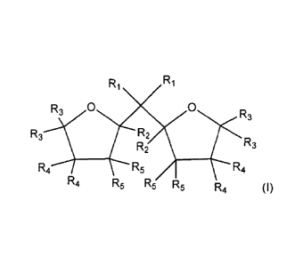
internal organic compound having the formula (I):
R1
0
R3 R2
R3
R2
R41i/R3 R5 / R4
(I)
R4 R5 R5 R5 R4
wherein in the formula (I) R1 to R5 are the same or different and can be
hydrogen, a linear or
branched Cl to 08-alkyl group, or a C3-08-alkylene group, or two or more of R1
to R5 can form
a ring, and the two oxygen-containing rings are individually saturated or
partially unsaturated or
unsaturated.
2a
Various embodiments of the present invention relate to a process for producing
copolymers of ethylene and at least one alpha-olefin having from 4 to 10
carbon atoms in the
presence of a solid Ziegler-Natta catalyst comprising of magnesium, titanium,
halogen and an
internal organic compound, the copolymer having a density of from 906 to 937
kg/m3 and a melt
flow rate MFR21 measured at 190 C under 21.6 kg load of from 3 to 150 g/10
min comprising the
steps of
(A) homopolymerising ethylene or copolymerising ethylene and a first alpha-
olefin having
from 4 to 10 carbon atoms in a fluid reaction mixture of a first
polymerisation stage in the presence
of the solid Ziegler-Natta catalyst, hydrogen and optionally the first alpha-
olefin wherein the molar
ratio of hydrogen to ethylene in the fluid reaction mixture of the first
polymerisation stage is from
200 to 50000 mol/kmol and the molar ratio of the first alpha-olefin to
ethylene in the fluid reaction
mixture of the first polymerisation stage is from 0 to 1500 mol/kmol, to
produce a first homo- or
copolymer of ethylene;
(B) introducing particles of the first homo- or copolymer of ethylene,
containing active solid
Ziegler-Natta catalyst dispersed therein, together with additional ethylene,
hydrogen and a
second alpha-olefin having from 4 to 10 carbon atoms into a second
polymerization stage and
copolymerising ethylene and said second alpha-olefin having from 4 to 10
carbon atoms in said
second polymerisation stage in the presence of the first homo- or copolymer of
ethylene and the
solid Ziegler-Natta catalyst to produce a polymer mixture comprising the first
homo- or copolymer
of ethylene and a second copolymer of ethylene, the polymer mixture having a
density of from
906 to 937 kg/m3 and a melt flow rate MFR21 of from 3 to 150 g/10 min;
(C) recovering the polymer mixture, characterised in that the solid Ziegler-
Natta catalyst
comprises an internal organic compound having the formula (I):
Ri Ri
R3 0 0
R3
R3 R2
R2 R3
(I)
R4 R5 R4
R4 R5 R5 R5 R4
wherein in the formula (I) R1 to R5 are the same or different and are
hydrogen, a linear or branched
Cl to C8-alkyl group, or a C3-C8-alkylene group, or two or more of IR, to R5
can form a ring, and
the two oxygen-containing rings are individually saturated or partially
unsaturated or unsaturated.
CA 2984124 2019-08-13
CA 02984124 2017-10-26
WO 2016/207270 PCT/EP2016/064511
3
Detailed Description
Definitions
By multimodal copolymer is meant a copolymer which contains distinct
components having
different average molecular weights or different contents of comonomer or
both. The multimodal
copolymer is produced by copolymerising ethylene and a comonomer in two or
more
polymerisation stages where the polymerisation conditions are sufficiently
different to allow
production of different polymers in different stages.
By continuously operating process is meant a process or a process stage into
which the
feedstock materials are continuously or intermittently introduced and from
which the product is
continuously or intermittently withdrawn. By continuous addition or withdrawal
is meant that an
uninterrupted stream goes in or flows out of the process or process stage. By
intermittent
addition or withdrawal is meant that during the operation of the process small
batches of raw
material are constantly added into or product is constantly withdrawn from the
process or
process stage. The cycle time between such batches is small compared to the
overall average
.. residence time of the process or process stage, such as not more than 10
A) of the overall
average residence time.
By fluid reaction mixture it is meant the fluid phase (liquid, gas or
supercritical) in which the
reactants (ethylene, comonomer and hydrogen) are dissolved. The particles
comprising the
catalyst and polymer are then suspended in the fluid reaction mixture.
In the present text the expressions "internal organic compound" and "internal
donor" are used
synonymously.
Catalyst
The solid catalyst component used in copolymerisation of ethylene is a solid
Ziegler-Natta
catalyst component for ethylene polymerisation, which solid Ziegler-Natta
catalyst component
comprises magnesium, titanium, halogen and an internal organic compound. The
internal donor
is selected from bi-(oxygen containing ring) compounds of formula (I)
Ri
0 0
R3 R2
R3
R2
R4A R5 t R4
R4 R5 R5 R5 R4
CA 02984124 2017-10-26
WO 2016/207270 PCT/EP2016/064511
4
(I)
where R1 to R5 are the same or different and can be hydrogen, a linear or
branched C1 to 08-
alkyl group, or a 03-08-alkylene group, or two or more of R1 to R5 can form a
ring,
the two oxygen-containing rings are individually saturated or partially
unsaturated or
unsaturated.
Accordingly, the catalyst used in the present invention comprises a solid
MgCl2 supported
component which is prepared by a method comprising the steps:
a) providing solid carrier particles of MgC12*mR0H adduct
b) pre-treating the solid carrier particles of step a) with a compound of
Group 13 metal
c) treating the pre-treated solid carried particles of step b) with a
transition metal compound
of Group 4 to 6
d) recovering the solid catalyst component
wherein the solid carrier particles are contacted with an internal organic
compound of formula (1)
before treating the solid carrier particles in step c)
0 0
N.,(3
R3 R2
R3
R2
R5
R4 R5 R5 R5 R4 (I)
and
wherein in the formula (1)
R1 to R5 are the same or different and can be hydrogen, a linear or branched
Ci to Cs-alkyl
group, or a 03-08-alkylene group, or two or more of R1 to R5 can form a ring,
the two oxygen-containing rings are individually saturated or partially
unsaturated or
unsaturated, and
CA 02984124 2017-10-26
WO 2016/207270 PCT/EP2016/064511
R in the adduct MgC12*mR0H is a linear or branched alkyl group with 1 to 12 C
atoms, and m is
0 to 6.
Accordingly, the internal organic compound of formula (I) is contacted with
the solid carrier
particles before treatment of solid carrier particles with the transition
metal compound of Group
5 4 to 6. Thus, said internal organic compound can be contacted with the
solid carrier particles
before step b), i.e. before pre-treating the solid carrier particles with
Group 13 metal compound,
or simultaneously with said pre-treatment step, or after step b), but before
treating the solid
carrier particles with the transition metal compound of Group 4 to 6.
Further, one object of the invention is to use the catalyst in accordance to
what was disclosed
above in the process for producing linear low density polyethylene in a
multistage process.
The catalyst will be described in the following in greater detail, referring
to the particular
preferred embodiments.
As used herein, the term Ziegler Natta (ZN) catalyst component is intended to
cover a catalyst
component comprising a transition metal compound of Group 4 to 6, a compound
of a metal of
Group 13 of the Periodic Table (IUPAC, Nomenclature of Inorganic Chemistry,
1989) and an
internal organic compound supported on MgCl2 based carrier.
Magnesium dihalide is used as a starting material for producing a carrier. The
solid carrier is a
carrier where alcohol is coordinated with Mg dihalide, preferably MgCl2. The
MgCl2 is mixed with
one or more alcohols having the formula ROH and the solid carrier MgC12*mR0H
is formed
according to the well-known methods. As examples, spray drying or spray
crystallisation
methods can be used to prepare the magnesium halide. Spherical and granular
MgC12*mR0H
carrier materials of different sizes (5-100 pm) are suitable to be used in the
present invention.
The alcohol in producing MgC12*mR0H carrier material is an alcohol ROH, where
R is a linear
or branched alkyl group containing 1 to 12 carbon atoms, preferably 1 to 8
carbon atoms, like 1
to 4 carbon atoms. Ethanol is typically used. In MgC12*mR0H, m is from 0 to 6,
more preferably
from 1 to 4, especially from 2.7 to 3.3.
MgC12*mR0H is available from commercial sources or can be prepared by methods
described
in prior art. Preparation methods of MgC12*mR0H carrier is described in
several patents e.g. in
EP-A-376936, EP-A-424049, EP-A-655073 and EP-A-614467.
Group 13 metal compound, used in step b) is preferably an aluminium compound.
Particularly
preferably the aluminium compound is an aluminium compound of the formula
Al(alkyl)1X3_x (II),
wherein each alkyl is independently an alkyl group of 1 to 12 carbon atoms,
preferably 1 to 8
CA 02984124 2017-10-26
WO 2016/207270 PCT/EP2016/064511
6
carbon atoms, more preferably 1 to 6 carbon atoms, Xis halogen, preferably
chlorine and l< x
3. The alkyl group can be linear, branched or cyclic, or a mixture of such
groups.
Preferred aluminium compounds are dialkyl aluminium chlorides or trialkyl
aluminium
compounds, for example dimethyl aluminium chloride, diethyl aluminium
chloride, di-isobutyl
aluminium chloride, and triethylaluminium or mixtures therefrom. Most
preferably the aluminium
compound is a trialkyl aluminium compound, especially triethylaluminium
compound.
The transition metal compound of Group 4 to 6 is preferably a Group 4
transition metal
compound or a vanadium compound and is more preferably a titanium compound.
Particularly
preferably the titanium compound is a halogen-containing titanium compound of
the formula
XyTi(OR8)4_y, wherein R8 is a C1_20 alkyl, preferably a 02-wand more
preferably a 02-8 alkyl group,
X is halogen, preferably chlorine and y is 1, 2, 3 or 4, preferably 3 or 4 and
more preferably 4.
Suitable titanium compounds include trialkoxy titanium monochlorides, dialkoxy
titanium
dichloride, alkoxy titanium trichloride and titanium tetrachloride. Preferably
titanium tetrachloride
is used.
The internal organic compound is selected from bi-cyclic ether compounds of
formula (I):
0 0
R3 R2
R3
R2
R4A R5 R4
R4 R5 R5 R5 R4 (I)
wherein in the formula (I)
R1 to R5 are the same or different and can be hydrogen, a linear or branched
C1 to 08-alkyl
group, or a 03-08-alkylene group, or two or more of R1 to R5 can form a ring,
and
whereby the two oxygen-containing rings are individually saturated or
partially unsaturated or
unsaturated.
Examples of preferred linear or branched Ci to 08-alkyl groups are methyl,
ethyl, n-propyl,
propyl, n-butyl, sec-butyl, tert-butyl, pentyl and hexyl groups.
Examples for preferred 03-08-alkylene groups are pentylene and butylene
groups.
CA 02984124 2017-10-26
WO 2016/207270 PCT/EP2016/064511
7
The two R1 are preferably the same and are a linear C1 to C4-alkyl groups,
more preferably
methyl or ethyl; or the two R1 form a ring with the carbon atom they are
attached to a ring with 3
to 7 carbon atoms , preferably cyclopentyl or cyclohexyl ring.
Most preferably both R1 are methyl.
.. R2 to R5 are the same or different and are preferably H or a C1 to C2-alkyl
groups, or two or
more of R2 to R5 residues can form a ring. If one or more rings are formed by
the residues R2 to
R5, these are more preferably formed by R3 and R4 and/or R4 and R5.
Preferably the residues R2 to R5 do not form rings and more preferably at most
two of the
residues R2 to R5 are a methyl, the others are H. Most preferably R2 to R5 are
all hydrogens.
Furthermore both oxygen-containing rings are preferably saturated or partially
unsaturated or
unsaturated. Each partially unsaturated or unsaturated oxygen-containing ring
can have one or
two double bonds.
More preferably both oxygen-containing rings are saturated.
In the most preferred embodiment, 2,2-di(2-tetrahydrofuryl)propane (DTHFP) is
used with the
isomers thereof. DTHFP is typically a 1:1 mol/mol diastereomeric mixture of
D,L-(rac)-DTHFP
and meso-DTHFP.
It has been found that using an internal organic compound that is enriched in
isomers of
DTHFP, that the catalyst morphological properties are not influenced. It was
found that by using
enriched rac-DTHFP, where the ratio of D,L-(rac)-DTHFP/meso-DTHFP is at least
2/1 mol/mol,
it was possible to produce the catalyst morphology as good as with the
equimolar (rac) and
(meso) mixture.
Enrichment was surprisingly successful via complexation with MgCl2.
When producing the supported catalyst component used in the present invention
it is especially
preferred that the internal organic compound, as defined above, is added to
the catalyst mixture
before, during or after the pre-treating of the MgCl2-mR0H with the Group 13
metal compound,
but before treating it with the compound of a transition metal of Group 4 to
6.
Thus, according to one suitable method the solid catalyst component is
prepared by a process
comprising the steps of:
CA 02984124 2017-10-26
WO 2016/207270 PCT/EP2016/064511
8
i) providing solid MgC12*mR0H carrier, wherein m is 1 to 4 and R is a linear
or branched
alkyl group containing 1 to 8 C atoms
ii) pre-treating the solid carrier particles of step i) with an Al compound
iii) adding the internal organic compound of formula (I) into the pre-treated
solid carrier of
step ii) or
iii') simultaneously with step ii) adding the internal organic compound of
formula (I) into the
solid carrier
iv) treating the pre-treated solid carried particles of step iii) or iii')
with TiCI4and
v) recovering the solid catalyst component
Thus, according to another suitable method the solid catalyst component is
prepared by a
process comprising the steps of:
i) providing solid MgC12*mR0H carrier, wherein m is 1 to 4 and R is a linear
or branched
alkyl group containing 1 to 8 C atoms
u-1) adding the internal organic compound of formula (I) into the solid
carrier of step i)
iii-1) pre-treating the solid carrier particles of step u-1) with an Al
compound
iv-1) treating the pre-treated solid carried particles of step iii-1) with
TiCI4and
v-1) recovering the solid catalyst component.
According to either one of the methods above the Al compound can be added to
the solid
carrier before or after adding the internal organic compound or simultaneously
with the internal
organic compound to the carrier.
Most preferably in the above-mentioned embodiments, m = 2.7 to 3.3, ROH is
ethanol,
aluminum compound is an aluminium trialkyl compound, such as triethyl
aluminium, and as
internal organic compound is 2,2-di(2-tetrahydrofuryl)propane, or 2,2-di-(2-
furan)-propane,
especially 2,2-di(2-tetrahydrofuryl)propane.
According to the catalyst preparation method of the present invention the pre-
treatment with the
Group 13 metal compound, preferably an aluminum compound, can be done by
adding a
solution of said aluminum compound in inert organic solvent, preferably in
inert aliphatic
CA 02984124 2017-10-26
WO 2016/207270 PCT/EP2016/064511
9
hydrocarbon solvent, for example in heptane. The method of the invention
allows use of a
concentrated aluminum compound solution. In the case where triethylaluminiun
(TEA) is used, a
15 to 100 wt-% solution of TEA in an inert hydrocarbon, preferably a 25 to 100
wt-% solution of
TEA in inert aliphatic hydrocarbon solvent, like in heptane can be used, or
neat TEA. It was
found that by using these more concentrated solutions, the morphology remains
advantageous
and a reduced amount of waste is produced.
The final solid catalyst component typically has Mg/Ti mol/mol ratio of from 1
to 10, preferably
from 2 to 8, especially from 3 to 7, Al/Ti mol/mol ratio of from 0.01 to 1,
preferably from 0.1 to
0.5 and Cl/Ti mol/mol ratio of from 5 to 20, preferably from 10 to 17.
Particles of the solid catalyst component of the invention are uniform in
particle size without
fines or agglomerates.
The supported catalyst component as described above allows the production of
polymers with
increased molecular weight. The increase in molecular weight is not made at
the expense of the
productivity of the catalyst. The productivity remains at an acceptably high
level or is even
increased compared to use of a catalyst component of similar type but using a
different internal
organic compound and/or prepared by adding the internal organic compound
during or after the
treatment step with TiCI4, or using said organic compound as external
additive. Thus, the
performance of the catalyst prepared by the method of the present invention
makes it possible
to broaden the preparation window of the polyethylene such that polymerisation
with both higher
and lower amounts of hydrogen is possible while retaining good productivity.
The catalyst used in the process of the invention comprises, in addition to
the solid catalyst
component as defined above, a cocatalyst, which is also known as an activator.
Cocatalysts are
organometallic compounds of Group 13 metal, typically aluminum compounds.
These
compounds include alkyl aluminium halides, preferably alkyl aluminium
chlorides, such as
ethylaluminium dichloride, diethylaluminium chloride, ethylaluminium
sesquichloride,
dimethylaluminium chloride and the like. They also include trialkylaluminium
compounds, such
as trimethylaluminium, triethylaluminium, tri-isobutylaluminium,
trihexylaluminium and tri-n-
octylaluminium. Also other aluminium alkyl compounds, such as
isoprenylaluminium, may be
used. Especially preferred cocatalysts are trialkylaluminiums, of which
triethylaluminium,
trimethylaluminium and tri-isobutylaluminium are particularly used.
The catalyst of the invention may also comprise an external additive, like
external donor.
External additives that can be used include ether compounds, typically
tetrahydrofuran, siloxane
or silane type of external donors and/or alkyl halides as is known from prior
art. The final solid
CA 02984124 2017-10-26
WO 2016/207270 PCT/EP2016/064511
catalyst component, i.e. the ZN solid catalyst component, obtained according
to any one of the
above described methods, is combined with an activator.
Suitable activators are optionally halogenated aluminium alkyl cocatalysts of
formula (V) (C1-04-
alkyl)-Al-X3, wherein X is chlorine, bromine, iodine or fluorine and p is 1, 2
or 3.
5 The C1-C4-alkyl groups can be linear or branched or cyclic, or a mixture
of such groups.
X is preferably chlorine or bromine, most preferably X is chlorine.
Suitable activators are for example trimethyl aluminium (TMA), triethyl
aluminium (TEA)
dimethyl aluminium chloride (DMAC), diethyl aluminium chloride (DEAC),
diisobutyl aluminium
chloride (DIBAC), ethyl aluminium dichloride (EADC), methyl aluminium
dichloride (MADC). A
10 preferred activator used in the process of the invention is
triethylaluminium.
The amount in which the activator is used depends on the specific catalyst and
the activator.
Typically triethylaluminium is used in such amount that the molar ratio of
aluminium to the
transition metal, like Al/Ti, is from 1 to 1000, preferably from 3 to 100 and
in particular from
about 5 to about 30 mol/mol.
Polymerisation process
The polymerisation process comprises the first polymerisation stage and the
second
polymerisation stage. In addition the process may comprise further
polymerisation stages, for
instance, for producing one or more additional polymer components or for
prepolymerising the
catalyst. The additional polymerisation stages may precede or succeed either
one of the first
and the second polymerisation stage. Furthermore, either one of the first and
second
polymerisation stages may be divided into two or more steps wherein either the
first homo- or
copolymer of ethylene or the second copolymer of ethylene is produced in two
or more steps
where each such step operates in conditions producing the respective first
homo- or copolymer
or second copolymer.
Prepolymerisation
The polymerisation steps may be preceded by a prepolymerisation step. The
purpose of the
prepolymerisation is to polymerise a small amount of polymer onto the catalyst
at a low
temperature and/or a low monomer concentration. By prepolymerisation it is
possible to improve
the performance of the catalyst in slurry and/or modify the properties of the
final polymer. The
prepolymerisation step is conducted in slurry.
CA 02984124 2017-10-26
WO 2016/207270 PCT/EP2016/064511
11
Thus, the prepolymerisation step may be conducted in a loop reactor. The
prepolymerisation is
then preferably conducted in an inert diluent, typically a hydrocarbon diluent
such as methane,
ethane, propane, n-butane, isobutane, pentanes, hexanes, heptanes, octanes
etc., or their
mixtures. Preferably the diluent is a low-boiling hydrocarbon having from 1 to
4 carbon atoms or
a mixture of such hydrocarbons.
The temperature in the prepolymerisation step is typically from 0 to 90 C,
preferably from 20 to
80 C and more preferably from 50 to 70 C.
The pressure is not critical and is typically from 1 to 150 bar, preferably
from 40 to 80 bar.
The amount of monomer is typically such that from about 0.1 to 1000 grams of
monomer per
__ one gram of solid catalyst component is polymerised in the
prepolymerisation step. As the
person skilled in the art knows, the catalyst particles recovered from a
continuous
prepolymerisation reactor do not all contain the same amount of prepolymer.
Instead, each
particle has its own characteristic amount which depends on the residence time
of that particle
in the prepolymerisation reactor. As some particles remain in the reactor for
a relatively long
time and some for a relatively short time, then also the amount of prepolymer
on different
particles is different and some individual particles may contain an amount of
prepolymer which
is outside the above limits. However, the average amount of prepolymer on the
catalyst typically
is within the limits specified above.
The molecular weight of the prepolymer may be controlled by hydrogen as it is
known in the art.
Further, antistatic additive may be used to prevent the particles from
adhering to each other or
the walls of the reactor, as disclosed in WO-A-96/19503 and WO-A-96/32420.
The catalyst components are preferably all (separately or together) introduced
to the
prepolymerisation step when a prepolymerisation step is present. However,
where the solid
catalyst component and the cocatalyst can be fed separately it is possible
that only a part of the
.. cocatalyst is introduced into the prepolymerisation stage and the remaining
part into subsequent
polymerisation stages. Also in such cases it is necessary to introduce so much
cocatalyst into
the prepolymerisation stage that a sufficient polymerisation reaction is
obtained therein.
Typically, the amounts of hydrogen and comonomer are adjusted so that the
presence of the
prepolymer has no effect on the properties of the final multimodal polymer.
Especially, it is
preferred that melt flow rate of the prepolymer is greater than the melt flow
rate of the final
polymer but smaller than the melt flow rate of the polymer produced in the
first polymerisation
stage. It is further preferred that the density of the prepolymer is greater
than the density of the
final polymer. Suitably the density is approximately the same as or greater
than the density of
CA 02984124 2017-10-26
WO 2016/207270 PCT/EP2016/064511
12
the polymer produced in the first polymerisation stage. Further, typically the
amount of the
prepolymer is not more than about 5 % by weight of the multimodal polymer
comprising the
prepolymer.
First polymerisation stage
In the first polymerisation stage a first homo- or copolymer of ethylene is
produced. This is done
by introducing a polymerisation catalyst, optionally through the
prepolymerisation stage or a
prior polymerisation stage as described above, into the first polymerisation
stage together with
ethylene, hydrogen and optionally an alpha-olefin comonomer.
Hydrogen is introduced into the first polymerisation stage for controlling the
MFR2 of the first
homo- or copolymer of ethylene. The amount of hydrogen is such that the molar
ratio of
hydrogen to ethylene in the fluid reaction mixture is within the range of from
200 to 50000
mol/kmol (or mo1/1000 mol), preferably of from 200 to 1000 mol/kmol. If the
first polymerisation
stage is conducted as a slurry polymerisation stage, preferably in a loop
reactor, the molar ratio
of hydrogen to ethylene in the fluid reaction mixture is suitably from 200 to
1000 mol/kmol,
preferably from 300 to 800 mol/kmol.
According to one embodiment the first homo- or copolymer of ethylene is a
homopolymer. Thus,
the first alpha-olefin is not present in the first polymerisation stage.
Hydrogen is present in an
amount described above.
According to another embodiment the first homo- or copolymer of ethylene is a
copolymer of
ethylene and the first alpha-olefin. In such case the molar ratio of the first
alpha-olefin to
ethylene in the fluid reaction mixture is from 100 to 1000 mol/kmol ,
preferably from 200 to 800
mol/kmol. The first alpha-olefin is preferably selected from the group
consisting of 1-butene, 1-
hexene and 4-methyl-1-pentene, more preferably consisting of 1-butene and 1-
hexene. Also in
this embodiment hydrogen is present in an amount as was described above.
When produced in the conditions as defined above the first homo- or copolymer
of ethylene
typically has a melt flow rate MFR2 of from 100 to 1000 g/10 min, preferably
from 150 to 750
g/10 min and more preferably from 200 to 600 g/10 min. Furthermore, the first
copolymer
typically has a density of from 930 to 980 kg/m3, preferably from 940 to 978
kg/m3 and most
preferably from 945 to 976 kg/m3.
When the first homo- or copolymer of ethylene is a copolymer of ethylene, it
then preferably has
a density of from 930 to 955 kg/m3, more preferably from 940 to 953 kg/m3 and
most preferably
from 945 to 953 kg/m3.
CA 02984124 2017-10-26
WO 2016/207270 PCT/EP2016/064511
13
As the person skilled in the art is aware of, the MFR2 and density ranges
apply for the first
homo- or copolymer of ethylene. If the first polymerisation stage is preceded
by another
polymerisation stage where a substantial amount of polymer is produced then
the above-
mentioned MFR2 and density ranges given for the first homo- or copolymer do
not necessarily
apply for the polymer mixture comprising the polymers produced in the prior
polymerisation
stage and the first polymerisation stage.
The first polymerisation stage is preferably conducted as a slurry
polymerisation. The slurry
polymerisation usually takes place in an inert diluent, typically a
hydrocarbon diluent such as
methane, ethane, propane, n-butane, isobutane, pentanes, hexanes, heptanes,
octanes etc., or
their mixtures. Preferably the diluent is a low-boiling hydrocarbon having
from 1 to 4 carbon
atoms or a mixture of such hydrocarbons. An especially preferred diluent is
propane, possibly
containing minor amount of methane, ethane and/or butane.
The ethylene content in the fluid reaction mixture may be from 1 to about 50 %
by mole,
preferably from about 2 to about 20 % by mole and in particular from about 2
to about 10 % by
mole. The benefit of having a high ethylene concentration is that the
productivity of the catalyst
is increased but the drawback is that more ethylene then needs to be recycled
than if the
concentration was lower.
The temperature in the first polymerisation stage is typically from 60 to 100
C, preferably from
70 to 95 C. An excessively high temperature should be avoided to prevent
partial dissolution of
the polymer into the diluent and the fouling of the reactor. The pressure is
from 1 to 150 bar,
preferably from 40 to 80 bar.
The slurry polymerisation may be conducted in any known reactor used for
slurry
polymerisation. Such reactors include a continuous stirred tank reactor and a
loop reactor. It is
especially preferred to conduct the polymerisation in a loop reactor. In such
reactors the slurry
is circulated with a high velocity along a closed pipe by using a circulation
pump. Loop reactors
are generally known in the art and examples are given, for instance, in US-A-
4582816, US-A-
3405109, US-A-3324093, EP-A-479186 and US-A-5391654. It is thus preferred to
conduct the
first polymerisation stage as a slurry polymerisation in one or more loop
reactors, more
preferably in one loop reactor.
The slurry may be withdrawn from the reactor either continuously or
intermittently. A preferred
way of intermittent withdrawal is the use of settling legs where slurry is
allowed to concentrate
before withdrawing a batch of the concentrated slurry from the reactor. The
use of settling legs
is disclosed, among others, in US-A-3374211, US-A-3242150 and EP-A-1310295.
Continuous
CA 02984124 2017-10-26
WO 2016/207270 PCT/EP2016/064511
14
withdrawal is disclosed, among others, in EP-A-891990, EP-A-1415999, EP-A-
1591460 and
WO-A-2007/025640. The continuous withdrawal is advantageously combined with a
suitable
concentration method, as disclosed in EP-A-1310295 and EP-A-1591460. It is
preferred to
withdraw the slurry from the first polymerisation stage continuously.
If the first homo- or copolymer of ethylene is the first copolymer of ethylene
then the first alpha-
olefin comonomer is introduced into the first polymerisation stage for
controlling the density of
the first copolymer of ethylene. The amount of comonomer needed to reach the
desired density
depends on the comonomer type, the catalyst used and the polymerisation
conditions,
especially on H2/C2 ratio.
The contents of hydrogen, ethylene and the first alpha-olefin comonomer may be
measured, as
it is known in the art, by withdrawing a sample stream from the reactor or
from the stream
withdrawn from the reactor, as disclosed in WO-A-1996035936, WO-A-1994027134
and EP-A-
460594. Suitably, such a sample stream is withdrawn from a pressure reduction
stage, or flash,
between the first and second polymerisation stages.
The average residence time in the first polymerisation stage is typically from
20 to 120 minutes,
preferably from 20 to 70 minutes. As it is well known in the art the average
residence time T can
be calculated from:
VR
T = - (eq. 1)
Qo
Where VR is the volume of the reaction space (in case of a loop reactor, the
volume of the
reactor, in case of the fluidised bed reactor, the volume of the fluidised
bed) and Qo is the
volumetric flow rate of the product stream (including the polymer product and
the fluid reaction
mixture).
It is possible, and occasionally preferred, to conduct the first
polymerisation stage in more than
one step, for instance in two steps. When the first polymerisation stage is
conducted in more
than one step the first homo- or copolymer of ethylene is a mixture of two or
more homo- or
copolymers of ethylene. In such a case all such steps should be conducted in
conditions as
described above. Further, the amount of the first homo- or copolymer of
ethylene is then the
sum of the amounts of polymers produced in all such steps.
Furthermore, as described above, it is possible that one or more additional
polymerisation
stages, where a polymer which is different from the first homo- or copolymer
of ethylene is
produced, precede the first polymerisation stage.
CA 02984124 2017-10-26
WO 2016/207270 PCT/EP2016/064511
Second polymerisation stage
In the second polymerisation stage a polymer mixture comprising the first homo-
or copolymer
of ethylene and a second copolymer of ethylene is formed. This is done by
introducing the
particles of the first homo- or copolymer of ethylene, containing active
catalyst dispersed
5 therein, together with additional ethylene and a second alpha-olefin
comonomer into the second
polymerisation stage. Hydrogen may be introduced for controlling the molecular
weight. This
causes the second copolymer of ethylene to form on the particles comprising
the first homo- or
copolymer of ethylene.
The melt flow rate MFR5 of the polymer mixture preferably is from 0.5 to 5.0
9/10 min, more
10 preferably from 0.8 to 4.0 g/10 min. The polymer mixture preferably has
MFR21 of from 20 to
150 g/10 min, more preferably 25 to 100 g/10 min. Furthermore, it preferably
has the flow rate
ratio FRR2115 of from 10 to 50, more preferably from 15 to 40.
The second alpha-olefin comonomer is selected from alpha-olefins containing
from 4 to 10
carbon atoms. The second alpha-olefin comonomer may be the same as or
different from the
15 .. first alpha-olefin comonomer, if the first alpha-olefin comonomer was
present. In one preferred
embodiment of the invention the first alpha-olefin comonomer and the second
alpha-olefin
comonomer are the same, such as 1-butene or 1-hexene, especially preferably 1-
butene. In
another preferred embodiment of the invention the first alpha-olefin comonomer
is different from
the second alpha-olefin comonomer. Then the first alpha-olefin comonomer can
be 1-butene
and the second alpha-olefin comonomer 1-hexene or 1-octene, more preferably 1-
hexene.
According to a further embodiment the first alpha-olefin comonomer is absent
and the second
alpha-olefin comonomer is 1-butene, 1-hexene or 1-octene, or their mixture,
preferably 1-
hexene. The content of the second alpha-olefin comonomer is controlled to
obtain the desired
density of the polymer mixture. Typically the polymer mixture has a density of
from 906 to 935
kg/m3, preferably from 910 to 932 kg/m3 and more preferably from 913 to 930
kg/m3.
When the polymer mixture has a density within the lower end of the range,
i.e., from 906 to 925
kg/m3, then it is preferred that the first homo- or copolymer of ethylene is a
copolymer of
ethylene and preferably has a density of from 930 to 955 kg/m3, more
preferably from 940 to
953 kg/m3 and most preferably from 945 to 953 kg/m3. When the polymer mixture
has a density
within the upper end of the range, i.e., from 925 to 935 kg/m3, then the first
homo- or copolymer
of ethylene may be a homopolymer of ethylene or a copolymer of ethylene and
the second
alpha olefin and it typically has a density of from 945 to 980 kg/m3,
preferably from 945 to 978
kg/m3 and most preferably from 948 to 975 kg/m3.
CA 02984124 2017-10-26
WO 2016/207270 PCT/EP2016/064511
16
The MFR21 of the second copolymer of ethylene cannot be measured because the
second
copolymer cannot be isolated from the polymer mixture.
Hydrogen feed is adjusted to achieve a desired melt flow rate (or molecular
weight) of the
polymer mixture. Suitably the hydrogen feed is controlled to maintain constant
hydrogen to
ethylene ratio in the fluid reaction mixture. The actual ratio depends on the
catalyst as well as
the type of the polymerisation. The desired polymer properties have been
obtained in gas phase
polymerisation in a fluidised bed reactor by maintaining the ratio in the gas
phase within the
range of from 10 to 150 mol/kmol, preferably from 20 to 100 mol/kmol, such as
from 30 to 90
mol/kmol.
The second alpha-olefin comonomer is typically introduced to maintain a
constant comonomer
to ethylene ratio in the fluid reaction mixture. The comonomer to ethylene
ratio that is needed to
produce a polymer with the desired density depends, among others, on the type
of comonomer
and the type of catalyst. With 1-hexene as a comonomer the desired polymer
properties have
been obtained in gas phase polymerisation in a fluidised bed reactor with a
molar ratio of 1-
hexene to ethylene in the gas phase of from 50 to 400 mol/kmol, preferably
from 100 to 250
mol/kmol and in particular from 120 to 220 mol/kmol.
Preferably the second polymerisation stage is conducted as a fluidised bed gas
phase
polymerisation. In a fluidised bed gas phase reactor an olefin is polymerised
in the presence of
a polymerisation catalyst in an upwards moving gas stream. The reactor
typically contains a
fluidised bed comprising the growing polymer particles containing the active
catalyst located
above a fluidisation grid.
The polymer bed is fluidised with the help of the fluidisation gas comprising
the olefin monomer,
eventual comonomer(s), eventual chain growth controllers or chain transfer
agents, such as
hydrogen, and eventual inert gas. The fluidisation gas is introduced into an
inlet chamber at the
bottom of the reactor. To make sure that the gas flow is uniformly distributed
over the cross-
sectional surface area of the inlet chamber the inlet pipe may be equipped
with a flow dividing
element as known in the art, e.g. US-A-4933149 and EP-A-684871. One or more of
the above-
mentioned components may be continuously added into the fluidisation gas to
compensate for
losses caused, among other, by reaction or product withdrawal.
From the inlet chamber the gas flow is passed upwards through a fluidisation
grid into the
fluidised bed. The purpose of the fluidisation grid is to divide the gas flow
evenly through the
cross-sectional area of the bed. Sometimes the fluidisation grid may be
arranged to establish a
gas stream to sweep along the reactor walls, as disclosed in WO-A-2005/087361.
Other types
CA 02984124 2017-10-26
WO 2016/207270 PCT/EP2016/064511
17
of fluidisation grids are disclosed, among others, in US-A-4578879, EP 600414
and EP-A-
721798. An overview is given in Geldart and Bayens: The Design of Distributors
for Gas-
fluidised Beds, Powder Technology, Vol. 42, 1985.
The fluidisation gas passes through the fluidised bed. The superficial
velocity of the fluidisation
gas must be greater that minimum fluidisation velocity of the particles
contained in the fluidised
bed, as otherwise no fluidisation would occur. On the other hand, the velocity
of the gas should
be lower than the onset velocity of pneumatic transport, as otherwise the
whole bed would be
entrained with the fluidisation gas. The minimum fluidisation velocity and the
onset velocity of
pneumatic transport can be calculated when the particle characteristics are
known by using
.. common engineering practise. An overview is given, among others in Geldart:
Gas Fluidisation
Technology, J.Wiley & Sons, 1986.
When the fluidisation gas is contacted with the bed containing the active
catalyst the reactive
components of the gas, such as monomers, comonomers and chain transfer agents,
react in
the presence of the catalyst to produce the polymer product. At the same time
the gas is heated
by the reaction heat.
The unreacted fluidisation gas is removed from the top of the reactor and
cooled in a heat
exchanger to remove the heat of reaction. The gas is cooled to a temperature
which is lower
than that of the bed to prevent the bed from heating because of the reaction.
It is possible to
cool the gas to a temperature where a part of it condenses. When the liquid
droplets enter the
.. reaction zone they are vaporised. The vaporisation heat then contributes to
the removal of the
reaction heat. This kind of operation is called condensed mode and variations
of it are
disclosed, among others, in WO-A-2007/025640, US-A-4543399, EP-A-699213 and WO-
A-
94/25495. It is also possible to add condensing agents into the recycle gas
stream, as disclosed
in EP-A-696293. The condensing agents are non-polymerisable components, such
as n-
.. pentane, isopentane, n-butane or isobutane, which are at least partially
condensed in the
cooler.
The gas is then compressed and recycled into the inlet chamber of the reactor.
Prior to the entry
into the reactor fresh reactants are introduced into the fluidisation gas
stream to compensate for
the losses caused by the reaction and product withdrawal. It is generally
known to analyse the
.. composition of the fluidisation gas and introduce the gas components to
keep the composition
constant. The actual composition is determined by the desired properties of
the product and the
catalyst used in the polymerisation.
CA 02984124 2017-10-26
WO 2016/207270 PCT/EP2016/064511
18
The catalyst may be introduced into the reactor in various ways, either
continuously or
intermittently. Among others, WO-A-01/05845 and EP-A-499759 disclose such
methods. Where
the gas phase reactor is a part of a reactor cascade the catalyst is usually
dispersed within the
polymer particles from the preceding polymerisation stage. The polymer
particles may be
introduced into the gas phase reactor as disclosed in EP-A-1415999 and WO-A-
00/26258.
The polymeric product may be withdrawn from the gas phase reactor either
continuously or
intermittently. Combinations of these methods may also be used. Continuous
withdrawal is
disclosed, among others, in WO-A-00/29452. Intermittent withdrawal is
disclosed, among
others, in US-A-4621952, EP-A-188125, EP-A-250169 and EP-A-579426.
The top part of the gas phase reactor may include a so called disengagement
zone. In such a
zone the diameter of the reactor is increased to reduce the gas velocity and
allow the particles
that are carried from the bed with the fluidisation gas to settle back to the
bed.
The bed level may be observed by different techniques known in the art. For
instance, the
pressure difference between the bottom of the reactor and a specific height of
the bed may be
recorded over the whole length of the reactor and the bed level may be
calculated based on the
pressure difference values. Such a calculation yields a time-averaged level.
It is also possible to
use ultrasonic sensors or radioactive sensors. With these methods
instantaneous levels may be
obtained, which of course may then be averaged over time to obtain a time-
averaged bed level.
Also antistatic agent(s) may be introduced into the gas phase reactor if
needed. Suitable
antistatic agents and methods to use them are disclosed, among others, in US-A-
5026795, US-
A-4803251, US-A-4532311, US-A-4855370 and EP-A-560035. They are usually polar
compounds and include, among others, water, ketones, aldehydes and alcohols.
The reactor may also include a mechanical agitator to further facilitate
mixing within the fluidised
bed. An example of suitable agitator design is given in EP-A-707513.
Typically the fluidised bed polymerisation reactor is operated at a
temperature within the range
of from 50 to 100 C, preferably from 65 to 90 C. The pressure is suitably
from 10 to 40 bar,
preferably from 15 to 30 bar.
The average residence time in the second polymerisation stage is typically
from 40 to 240
minutes, preferably from 60 to 180 minutes.
As discussed above, it is preferred to conduct the second polymerisation stage
in gas phase in
one or more gas phase reactors, more preferably in one fluidised bed reactor.
CA 02984124 2017-10-26
WO 2016/207270 PCT/EP2016/064511
19
The polymer mixture typically comprises from 25 to 57 % by weight of the first
homo- or
copolymer and from 43 to 75 % by weight of the second copolymer. Preferably
the polymer
mixture comprises from 35 to 57 % by weight of the first homo- or copolymer of
ethylene and
from 43 to 65 % by weight of the second copolymer of ethylene. The polymer
mixture may
contain other polymers in addition to the first homo- or copolymer of ethylene
and the second
copolymer of ethylene but the contents of the first homo- or copolymer of
ethylene and the
second copolymer of ethylene must be within the above-mentioned limits.
According to the most preferred embodiment the polymerisation process of the
present
invention is conducted in a cascaded sequence comprising at least one loop
reactor followed by
at least one gas phase reactor.
Extrusion
When the polymer mixture has been removed from the polymerisation reactor it
is subjected to
process steps for removing residual hydrocarbons from the polymer. Such
processes are well
known in the art and can include pressure reduction steps, purging steps,
stripping steps,
extraction steps and so on. Also combinations of different steps are possible.
According to one preferred process a part of the hydrocarbons is removed from
the polymer
powder by reducing the pressure. The powder is then contacted with steam at a
temperature of
from 90 to 110 C for a period of from 10 minutes to 3 hours. Thereafter the
powder is purged
with inert gas, such as nitrogen, over a period of from 1 to 60 minutes at a
temperature of from
20 to 80 C.
According to another preferred process the polymer powder is subjected to a
pressure reduction
as described above. Thereafter it is purged with an inert gas, such as
nitrogen, over a period of
from 20 minutes to 5 hours at a temperature of from 50 to 90 C. The inert gas
may contain
from 0.0001 to 5 %, preferably from 0.001 to 1 %, by weight of components for
deactivating the
catalyst contained in the polymer, such as steam.
The purging steps are preferably conducted continuously in a settled moving
bed. The polymer
moves downwards as a plug flow and the purge gas, which is introduced to the
bottom of the
bed, flows upwards.
Suitable processes for removing hydrocarbons from polymer are disclosed in WO-
A-02/088194,
EP-A-683176, EP-A-372239, EP-A-47077 and GB-A-1272778.
CA 02984124 2017-10-26
WO 2016/207270 PCT/EP2016/064511
After the removal of residual hydrocarbons the polymer is preferably mixed
with additives as it is
well known in the art. Such additives include antioxidants, process
stabilisers, neutralisers,
lubricating agents, nucleating agents, pigments and so on.
The polymer particles are mixed with additives and extruded to pellets as it
is known in the art.
5 Preferably a counter-rotating twin screw extruder is used for the
extrusion step. Such extruders
are manufactured, for instance, by Kobe and Japan Steel Works. A suitable
example of such
extruders is disclosed in EP-A-1600276. Typically the specific energy input
(SEI) is during the
extrusion within the range of from 180 to 230 kWh/ton. The melt temperature is
typically from
220 to 290 'C.
10 Benefits of the invention
The process according to the present invention operates smoothly and without
difficulty.
Especially, the catalysts have good productivity in the later stages of the
process. Further, the
catalysts have a good reactivity towards the comonomer. The dew point
temperature in the gas
phase reactor is low with the catalysts of the invention. When operating gas
phase at 85 C, the
15 dew point temperature is preferred to be not more than 70 C, more
preferably not more than 65
C . With the catalysts of the invention the dew point temperature is
substantially lower than 65
C (48.9-57.0 C), thus there are no operational problems. If the dew point
temperature is above
70 C operability will be worse, there is a risk of sheeting and chunking in
the reactor.
The gas phase reactor can be operated with a low level of condensable
material. Therefore, the
20 amount of residual hydrocarbon in the polymer withdrawn from the process
is small. This
simplifies the post-reactor treatment of the resulting polymer. Especially,
the purging step to
remove residual hydrocarbons from the polymer can be conducted economically.
The catalysts used in the process of the invention are less sensitive to
hydrogen than some
prior art catalysts. This allows controlling the MFR of the resulting bimodal
polymer in the step
where the high molecular weight copolymer of ethylene is produced. It is
possible to produce
these bimodal copolymers of ethylene with high molecular weight in a plant
scale. Because of
the higher H2 sensitivity of the prior art catalyst it is not possible to
obtain similar molecular
weights in plant scale where at least some amount of hydrogen is always fed to
the gas phase
reactor.
The copolymers of ethylene produced by the process according to the present
invention have
better or similar dart drop values compared to prior art.
CA 02984124 2017-10-26
WO 2016/207270 PCT/EP2016/064511
21
Description of methods
Melt flow rate
Melt flow rate (MFR) was determined according to ISO 1133 at 190 C. The load
under which
the measurement is conducted is given as a subscript. Thus, the MFR under the
load of 2.16 kg
is denoted as MFR2. The melt flow rate MFR21 is correspondingly determined at
190 C under a
load of 21.6 kg and MFR5 under a load of 5 kg.
Density
Density of the polymer was measured according to ISO 1183-1:2004 Method A on
compression
moulded specimen prepared according to EN ISO 1872-2 (Feb 2007) and is given
in kg/m3.
Reactor gas composition
Reactor gas composition in a slurry reactor can be measured, as is well known
in the art, from
the flash gas after the reactor by using on-line gas chromatography, as
disclosed, for instance,
in WO-A-1996035936.
Reactor gas composition in a gas phase reactor can be analysed from the
circulation gas by
using on-line chromatography, as it is well known in the art.
The instruments are calibrated, as it is known in the art, with calibration
gas mixtures having a
known composition which is close to that of the gas mixture present in the
polymerisation
process.
Dart drop strength (DDI)
Dart-drop is measured using ASTM D1709, method A (Alternative Testing
Technique) from the
film samples. A dart with a 38 mm diameter hemispherical head is dropped from
a height of
0.66 m onto a film clamped over a hole. Successive sets of twenty specimens
are tested. One
weight is used for each set and the weight is increased (or decreased) from
set to set by
uniform increments. The weight resulting in failure of 50 % of the specimens
is calculated and
reported.
Quantification of microstructure by NMR spectroscopy
Quantitative nuclear-magnetic resonance (NMR) spectroscopy was used to
quantify the
comonomer content of the polymers.
CA 02984124 2017-10-26
WO 2016/207270 PCT/EP2016/064511
22
Quantitative 13C{11-1} NMR spectra recorded in the molten-state using a Bruker
Advance III 500
NMR spectrometer operating at 500.13 and 125.76 MHz for iH and 13C
respectively. All spectra
were recorded using a 13C optimised 7 mm magic-angle spinning (MAS) probehead
at 150 C
using nitrogen gas for all pneumatics. Approximately 200 mg of material was
packed into a 7
mm outer diameter zirconia MAS rotor and spun at 4 kHz. This setup was chosen
primarily for
the high sensitivity needed for rapid identification and accurate
quantification. {k1imke06,
parkin50n07, ca5tign011e509} Standard single-pulse excitation was employed
utilising the NOE
at short recycle delays{pollard04, k1imke06} and the RS-HEPT decoupling scheme
{fi11ip05,griffin07}. A total of 1024 (1k) transients were acquired per
spectra.
Quantitative 130{11-1} NMR spectra were processed, integrated and relevant
quantitative
properties determined from the integrals. All chemical shifts are internally
referenced to the bulk
methylene signal (6+) at 30.00 ppm {randa1189}.
The amount of ethylene was quantified using the integral of the methylene (6+)
sites at 30.00
ppm accounting for the number of reporting sites per monomer:
E =1,34 2
The presence of isolated comonomer units is corrected for based on the number
of isolated
comonomer units present:
Etota I = E + (3*B + 2*H )12
where B and H are defined for their respective comonomers. Correction for
consecutive and
non-consecutive commoner incorporation, when present, is undertaken in a
similar way.
Characteristic signals corresponding to the incorporation of 1-butene were
observed and the
comonomer fraction calculated as the fraction of 1-butene in the polymer with
respect to all
monomer in the polymer:
fBtotal = ( Btotal / ( Etotal + Btotal + Htotal )
The amount isolated 1-butene incorporated in EEBEE sequences was quantified
using the
integral of the *B2 sites at 38.3 ppm accounting for the number of reporting
sites per
comonomer:
B = l*B2
The amount consecutively incorporated 1-butene in EEBBEE sequences was
quantified using
the integral of the aaB2B2 site at 39.4 ppm accounting for the number of
reporting sites per
comonomer:
BB = 2 * laaB2B2
The amount non-consecutively incorporated 1-butene in EEBEBEE sequences was
quantified
using the integral of the 1386262 site at 24.7 ppm accounting for the number
of reporting sites
per comonomer:
BEB = 2 *11313B2B2
CA 02984124 2017-10-26
WO 2016/207270 PCT/EP2016/064511
23
Due to the overlap of the *B2 and *I3B2B2 sites of isolated (EEBEE) and non-
consecutively
incorporated (EEBEBEE) 1-butene respectively the total amount of isolated 1-
butene
incorporation is corrected based on the amount of non-consecutive 1-butene
present:
B = l*B2- 2 * 11313B2B2
The total 1-butene content was calculated based on the sum of isolated,
consecutive and non-
consecutively incorporated 1-butene:
Btotal = B + BB + BEB
The total mole fraction of 1-butene in the polymer was then calculated as:
fB = ( Btotal / ( Etotal + Btotal + Htotal )
Characteristic signals corresponding to the incorporation of 1-hexene were
observed and the
comonomer fraction calculated as the fraction of 1-hexene in the polymer with
respect to all
monomer in the polymer:
fHtotal = ( Htotal / ( Etotal + Btotal + Htotal )
The amount isolated 1-hexene incorporated in EEHEE sequences was quantified
using the
integral of the *B4 sites at 39.9 ppm accounting for the number of reporting
sites per
comonomer:
H = l*B4
The amount consecutively incorporated 1-hexene in EEHHEE sequences was
quantified using
the integral of the aaB4B4 site at 40.5 ppm accounting for the number of
reporting sites per
comonomer:
HH = 2 * laaB4B4
The amount non-consecutively incorporated 1-hexene in EEHEHEE sequences was
quantified
using the integral of the 1306464 site at 24.7 ppm accounting for the number
of reporting sites
per comonomer:
HEH = 2 *113136464
The total mole fraction of 1-hexene in the polymer was then calculated as:
fH = ( Htotal / ( Etotal + Btotal + Htotal )
The mole percent comonomer incorporation is calculated from the mole fraction:
B [mol%] = 100 *fB
H [mol /0] = 100 *fH
The weight percent comonomer incorporation is calculated from the mole
fraction:
B [wt%] = 100 * ( fB * 56.11)1 ( (fB * 56.11) + (fH * 84.16) + ((1-(fB + fH))
* 28.05) )
H [wt%] = 100 * ( fH * 84.16 ) / ( (fB * 56.11) + (fH * 84.16) + ((1-(fB +
fH)) * 28.05) )
.. k1imke06
Klimke, K., Parkinson, M., Piel, C., Kaminsky, W., Spiess, H.W., Wilhelm, M.,
Macromol.
CA 02984124 2017-10-26
WO 2016/207270 PCT/EP2016/064511
24
Chem. Phys. 2006;207:382.
parkinson07
Parkinson, M., Klimke, K., Spiess, H.W., Wilhelm, M., Macromol. Chem. Phys.
2007;208:2128.
pollard04
Pollard, M., Klimke, K., Graf, R., Spiess, H.W., Wilhelm, M., Sperber, 0.,
Piel, C., Kaminsky,
W., Macromolecules 2004;37:813.
filip05
Filip, X., Tripon, C., Filip, C., J. Mag. Resn. 2005, 176, 239
griffin07
Griffin, J.M., Tripon, C., Samoson, A., Filip, C., and Brown, S.P., Mag. Res.
in Chem. 2007
45, Si, S198
castignolles09
Castignolles, P., Graf, R., Parkinson, M., Wilhelm, M., Gaborieau, M., Polymer
50 (2009)
2373
busico01
Busico, V., Cipullo, R., Prog. Polym. Sci. 26 (2001) 443
busico97
Busico, V., Cipullo, R., Monaco, G., Vacatello, M., Segre, A.L.,
Macromoleucles 30 (1997)
6251
zhou07
Zhou, Z., Kuemmerle, R., Qiu, X., Redwine, D., Cong, R., Taha, A., Baugh, D.
Winniford, B.,
J. Mag. Reson. 187 (2007) 225
busico07
Busico, V., Carbonniere, P., Cipullo, R., Pellecchia, R., Severn, J.,
Talarico, G., Macromol.
Rapid Commun. 2007, 28, 1128
resconi00
Resconi, L., Cavallo, L., Fait, A., Piemontesi, F., Chem. Rev. 2000, 100, 1253
CA 02984124 2017-10-26
WO 2016/207270 PCT/EP2016/064511
Examples
Catalyst Preparation for Catalysts 1 and 2
Preparation of pre-treated support material for Catalyst 1:
A jacketed 160 dm3 stainless steel reactor equipped with a helical mixing
element was
5 pressurized with N2 to 2.0 barg and depressurized down to 0.2 barg until
the 02 level was less
than 3 ppm. The vessel was then charged with heptane (20.5 kg) and 2,2-
di(tetrahydrofuryl)propane (0.38 kg; 2.06 mol; DTHFP). The obtained mixture
was stirred for 20
min at 40 rpm. The 45 pm MgC12*3Et0H carrier (5.0 kg; DTHFP/Mg = 0.1 mol/mol;
20.3 mol of
Mg; 9.86 wt-% of Mg) was added to the reactor with stirring. This suspension
was cooled to
10 approximately -20 C and the 25 wt% solution of triethylaluminum (30.4
kg, 66.6 mol of Al;
Al/Et0H = 1.0 mol/mol) in heptane was added in aliquots during 2.5 h time
while keeping the
temperature below 0 C. After the TEA addition, the reaction mixture was
gradually heated to 80
C over a period of 2.5 h and kept at this temperature for additional 20 min at
40 rpm. The
suspension was allowed to settle for 10 min, and the mother liquor was removed
through a 20
15 pm filter net in the bottom of the reactor during 10 min. The vessel was
charged with warm
toluene (43 kg) and then stirred at 40 rpm for 20 min at 40-60 C. The
suspension was allowed
to settle for 10 min at 40 C and the liquid removed through a 20 pm filter
net in the bottom of
the reactor during 10 min.
Catalyst preparation for Catalyst 1:
20 The vessel containing the pre-treated support material was charged with
toluene (43 kg) and
then cooled to approximately 30 C. Neat TiCI4 (3.85 kg, 20.3 mol; Ti/Mg =1.0
mol/mol) was
added. The obtained suspension was heated to approximately 90 C over a period
of 2 h and
kept at this temperature for additional 1 h with stirring at 40 rpm. The
suspension was allowed to
settle for 10 min at approximately 90 C and the mother liquor was removed
through a 20 pm
25 filter net in the bottom of the reactor during 10 min. The obtained
solid material was washed
twice with toluene (43 kg each) at P..- 90 C and once with heptane (34 kg) at
40 C. All three of
these washing steps used the same sequence of events: addition of preheated
(90 or 40 C)
solvent, then stirring at 40 rpm for 30 min, allowing the solid to settle for
10 min, and then
removal of liquid through a 20 pm filter net in the bottom of the reactor
during 10 min.
The obtained catalyst was mixed with 15 kg of white oil and dried 4 h at 40-50
C with nitrogen
flow (2 kg/h) and vacuum (-1 barg). The dry catalyst yield was 2.62 kg (83.5 %
based on Mg).
CA 02984124 2017-10-26
WO 2016/207270 PCT/EP2016/064511
26
Preparation of pre-treated support material for Catalyst 2:
A jacketed 160 dm3 stainless steel reactor equipped with a helical mixing
element was
pressurized with N2 to 2.0 barg and depressurized down to 0.2 barg until the
02 level was less
than 3 ppm. The vessel was then charged with heptane (20,5 kg) and 2,2-
.. di(tetrahydrofuryl)propane (0,518 kg; 2,81 mol; DTHFP). The obtained
mixture was stirred for 20
min at 40 rpm. The MgC12*3Et0H carrier (6,5 kg; DTHFP/Mg = 0.1 mol/mol; 27,5
mol of Mg;
10,29 wt-% of Mg; dlo = 13,5 pm, d50 = 21,5 pm and d90 = 34,2 pm, granular
shaped, Span =
0,96) was added to the reactor with stirring. This suspension was cooled to
approximately -20
C and the 33 wt% solution of triethylaluminum (29,2 kg, 84,3 mol of Al;
Al/Et0H = 1,0 mol/mol)
in heptane was added in aliquots during 2,5 h time while keeping the
temperature below 10 C.
After the TEA addition, the reaction mixture was gradually heated to 80 C
over a period of 2,4 h
and kept at this temperature for additional 20 min at 40 rpm. The suspension
was allowed to
settle for 10 min, and the mother liquor was removed through a 10 pm filter
net in the bottom of
the reactor during 15 min. The vessel was charged with warm toluene (43 kg)
and then stirred
at 40 rpm for 38 min at 55-70 C. The suspension was allowed to settle for 10
min at 50-55 C
and the liquid removed through a 10 pm filter net in the bottom of the reactor
during 15 min.
Catalyst preparation for Catalyst 2:
The vessel containing the pre-treated support material was charged with
toluene (43 kg) and
then cooled to approximately 30 C. Neat TiCI4 (5,22 kg, 27,5 mol; Ti/Mg =1.0
mol/mol) was
added. The obtained suspension was heated to approximately 90 C over a period
of 2 h and
kept at this temperature for additional 1 h with stirring at 40 rpm. The
suspension was allowed to
settle for 10 min at approximately 90 C and the mother liquor was removed
through a 10 pm
filter net in the bottom of the reactor during 15 min. The obtained solid
material was washed
twice with toluene (43 kg each) at 90 C and once with heptane (34 kg) at ¨40
C. All three of
.. these washing steps used the same sequence of events: addition of preheated
(90 or 40 C)
solvent, then stirring at 40 rpm for 30 min, allowing the solid to settle for
10 min, and then
removal of liquid through a 10 pm filter net in the bottom of the reactor
during 15 min.
The obtained catalyst was mixed with 20 kg of white oil and dried 4 h at 40-50
C with nitrogen
flow (2 kg/h) and vacuum (-1 berg). The catalyst was taken out from the
reactor and reactor was
.. flushed with another 20 kg of oil and taken out to the same drum. The dry
catalyst yield was
3.74 kg (75.9 % based on Mg).
27
Example 1
A loop reactor having a volume of 50 dm3 was operated at a temperature of 70
C and a pressure
of 58 bar. Into the reactor were fed ethylene, 1-butene, propane diluent and
hydrogen so that the
feed rate of ethylene was 4.0 kg/h, 1-butene was 150 g/h, hydrogen was 40 g/h
and propane was
48 kg/h. Also 7 g/h of a solid polymerization catalyst component produced as
described above in
Catalyst Preparation for Catalyst 1 was introduced into the reactor together
with triethylaluminium
cocatalyst so that the molar ratio of Al/Ti was about 15. The estimated
production rate was 3.8
kg/h.
A stream of slurry was continuously withdrawn and directed to a loop reactor
having a volume of
150 dm3 and which was operated at a temperature of 95 C and a pressure of 56
bar. Into the
reactor were further fed additional ethylene, propane diluent and hydrogen so
that the ethylene
concentration in the fluid mixture was 1.8 % by mole, the hydrogen to ethylene
ratio was 840
mol/kmol and the fresh propane feed was 30 kg/h. The production rate was 11
kg/h.
A stream of slurry from the reactor was withdrawn intermittently and directed
into a loop reactor
having a volume of 350 dm3 and which was operated at 95 C temperature and 54
bar pressure.
Into the reactor was further added a fresh propane feed of 47 kg/h and
ethylene, and hydrogen
so that the ethylene content in the fluid reaction mixture was 2.6 mai-% and
the molar ratio of
hydrogen to ethylene was 300 mol/kmol. The ethylene polymer withdrawn from the
reactor had
MFR2 of 180 g/10 min and density of 971 kg/m3. The production rate was 30
kg/h.
The slurry was withdrawn from the loop reactor intermittently and directed to
a flash vessel
operated at a temperature of 50 C and a pressure of 3 bar. From there the
polymer was directed
to a fluidized bed gas phase reactor operated at a pressure of 20 bar and a
temperature of 80 C.
Additional ethylene, 1-hexene comonomer, nitrogen as inert gas and hydrogen
were added so
that the ethylene content in the fluid reaction mixture was 11 mol-%, the
ratio of hydrogen to
ethylene was 44 mol/kmol and the molar ratio of 1-hexene to ethylene was 180
mol/kmol. The
polymer production rate in the gas phase reactor was 43 kg/h and thus the
total polymer
withdrawal rate from the gas phase reactor was about 88 kg/h. The polymer had
a melt flow rate
MFRS of 2.1 g/10 min and a density of 931 kg/m3. The production split (weight-
%
prepolymer/weight-% 1st stage component/weight-% 2nd stage component/weight-%
3rd stage
component) was 4/13/34/49.
The polymer powder was mixed under nitrogen atmosphere with 500 ppm of Ca-
stearate and
1200 ppm of lrganox TM B225. Then it was compounded and extruded under
nitrogen atmosphere
CA 2984124 2019-02-14
CA 02984124 2017-10-26
WO 2016/207270 PCT/EP2016/064511
28
to pellets by using a CIMP90 extruder so that the SEI was 200 kWh/ton and the
melt
temperature 250 C.
Examples 2 to 4
The procedure of Example 1 was repeated except that the hydrogen feed into the
prepolymerisation reactor was 20 g/h and the conditions were as shown in Table
1.
Examples 5 and 6
A loop reactor having a volume of 50 dm3 was operated at a temperature of 70
C and a
pressure of 56 bar. Into the reactor were fed ethylene, 1-butene, propane
diluent and hydrogen
so that the feed rate of ethylene was 2.0 kg/h, 1-butene was 50 g/h, hydrogen
was 2 g/h and
propane was 50 kg/h. Also 15-20 g/h of a solid polymerization catalyst
component produced as
described above in Catalyst Preparation for Catalyst 2 was introduced into the
reactor together
with triethylaluminium cocatalyst so that the molar ratio of Al/Ti was about
15. The estimated
production rate was 1.8 kg/h.
A stream of slurry was continuously withdrawn and directed to a loop reactor
having a volume of
.. 150 dm3 and which was operated at a temperature of 95 C and a pressure of
53 bar. Into the
reactor were further fed additional ethylene, propane diluent and hydrogen.
The fresh propane
feed was 41 kg/h. The production rate was 17 kg/h.
A stream of slurry from the reactor was withdrawn intermittently and directed
into a loop reactor
having a volume of 350 dm3 and which was operated at 95 C temperature and 51
bar pressure.
Into the reactor was further added a fresh propane feed of 43 kg/h and
ethylene, and hydrogen.
The production rate was 25 kg/h.
The slurry was withdrawn from the loop reactor intermittently and directed to
a flash vessel.
From there the polymer was directed to a fluidized bed gas phase reactor
operated at a
pressure of 20 bar and a temperature of 80 C. Additional ethylene, 1-hexene
comonomer,
.. nitrogen as inert gas and hydrogen were added. The polymer production rate
in the gas phase
reactor was 58 kg/h and thus the total polymer withdrawal rate from the gas
phase reactor was
about 100 kg/h.
Otherwise the procedure of Example 1 repeated except that the conditions were
as shown in
Table 1.
CA 02984124 2017-10-26
WO 2016/207270 PCT/EP2016/064511
29
Example 7
A loop reactor having a volume of 50 dm3 was operated at a temperature of 70
C and a
pressure of 58 bar. Into the reactor were ethylene, 1-butene, propane diluent
and hydrogen so
that the feed rate of ethylene was 4.0 kg/h, hydrogen was 20 g/h and propane
was 48 kg/h. Also
12 g/h of a solid polymerization catalyst component produced as described
above in Catalyst
Preparation for Catalyst 1 was introduced into the reactor together with
triethylaluminium
cocatalyst so that the molar ratio of Al/Ti was about 15. The production rate
was 3.8 kg/h.
A stream of slurry was continuously withdrawn and directed to a loop reactor
having a volume of
150 dm3 and which was operated at a temperature of 85 C and a pressure of 56
bar. Into the
reactor were further fed additional ethylene, 1-butene comonomer, propane
diluent and
hydrogen so that the ethylene concentration in the fluid mixture was 3.8 % by
mole, the
hydrogen to ethylene ratio was 630 mol/kmol, the molar ratio of 1-butene to
ethylene was 580
mol/kmol and the fresh propane feed was 30 kg/h. The production rate was 15
kg/h. The
copolymer withdrawn from the reactor had a density of 943 kg/m3 and MFR2 of
410 g/10 min.
__ A stream of slurry from the reactor was withdrawn intermittently and
directed into a loop reactor
having a volume of 350 dm3 and which was operated at 85 C temperature and 54
bar pressure.
Into the reactor was further added a fresh propane feed of 48 kg/h and
ethylene, 1-butene and
hydrogen so that the ethylene content in the fluid reaction mixture was 2.3
mol-c1/0, the molar
ratio of 1-butene to ethylene was 640 mol/kmol and the molar ratio of hydrogen
to ethylene was
__ 460 mol/kmol. The ethylene copolymer withdrawn from the reactor had MFR2 of
640 g/10 min
and density of 946 kg/m3. The production rate was 27 kg/h.
The slurry was withdrawn from the loop reactor intermittently and directed to
a flash vessel
operated at a temperature of 50 C and a pressure of 3 bar. From there the
polymer was
directed to a fluidized bed gas phase reactor operated at a pressure of 20 bar
and a
temperature of 80 C. Ethylene, 1-hexene comonomer, nitrogen as inert gas and
hydrogen were
added so that the ethylene content in the fluid reaction mixture was 7.1 mol-
/0, the ratio of
hydrogen to ethylene was 29 mol/kmol and the molar ratio of 1-hexene to
ethylene was 180
mol/kmol. The polymer production rate in the gas phase reactor was 48 kg/h and
thus the total
polymer withdrawal rate from the gas phase reactor was about 95 kg/h. The
polymer had a melt
flow rate MFR5 of 2.3 g/10 min and a density of 919 kg/m3. The production
split (weight-%
prepolymer/weight-% 181 stage component/weight- /0 2nd stage component/weight-
% 3rd stage
component) was 4/17/28/51.
CA 02984124 2017-10-26
WO 2016/207270 PCT/EP2016/064511
The polymer powder was mixed under nitrogen atmosphere with 500 ppm of Ca-
stearate and
1200 ppm of Irganox B225. Then it was compounded and extruded under nitrogen
atmosphere
to pellets by using a CIMP90 extruder so that the SEI was 200 kWh/ton and the
melt
temperature 250 C.
5 Examples 8 and 9
The procedure of Example 7 was repeated except that the conditions were as
shown in Table 2.
Example 10
A loop reactor having a volume of 50 dm3 was operated at a temperature of 70
C and a
pressure of 56 bar. Into the reactor were ethylene, 1-butene, propane diluent
and hydrogen so
10 that the feed rate of ethylene was 2.0 kg/h, 1-butene was 50 g/h,
hydrogen was 2 g/h and
propane was 47 kg/h. Also 3 g/h of a solid polymerization catalyst component
produced as
described above in Catalyst Preparation for Catalyst 2 was introduced into the
reactor together
with triethylaluminium cocatalyst so that the molar ratio of Al/Ti was about
15. The production
rate was 1.9 kg/h.
15 A stream of slurry was continuously withdrawn and directed to a loop
reactor having a volume of
150 dm3 and which was operated at a temperature of 85 C and a pressure of 53
bar. Into the
reactor were further fed additional ethylene, 1-butene comonomer, propane
diluent and
hydrogen so that the ethylene concentration in the fluid mixture was 2.9 A by
mole, the
hydrogen to ethylene ratio was 860 mol/kmol, the molar ratio of 1-butene to
ethylene was 280
20 .. mol/kmol and the fresh propane feed was 47 kg/h. The production rate was
17 kg/h. The
polymer withdrawn from the reactor had a density of 952 kg/m3 and MFR2 of 220
g/10 min.
A stream of slurry from the reactor was withdrawn intermittently and directed
into a loop reactor
having a volume of 350 dm3 and which was operated at 85 C temperature and 50
bar pressure.
Into the reactor was further added a fresh propane feed of 91 kg/h and
ethylene, 1-butene and
25 hydrogen so that the ethylene content in the fluid reaction mixture was
2.7 mol-%, the molar
ratio of 1-butene to ethylene was 480 mol/kmol and the molar ratio of hydrogen
to ethylene was
460 mol/kmol. The ethylene copolymer withdrawn from the reactor had MFR2 of
140 g/10 min
and density of 952 kg/m3. The production rate was 24 kg/h.
The slurry was withdrawn from the loop reactor intermittently and directed to
a flash vessel
30 operated at a temperature of 50 C and a pressure of 3 bar. From there
the polymer was
directed to a fluidized bed gas phase reactor operated at a pressure of 20 bar
and a
temperature of 80 C. Ethylene, 1-hexene comonomer, nitrogen as inert gas and
hydrogen were
CA 02984124 2017-10-26
WO 2016/207270 PCT/EP2016/064511
31
added so that the ethylene content in the fluid reaction mixture was 11 mol-
/0, the ratio of
hydrogen to ethylene was 54 mol/kmol and the molar ratio of 1-hexene to
ethylene was 160
mol/kmol. The polymer production rate in the gas phase reactor was 52 kg/h and
thus the total
polymer withdrawal rate from the gas phase reactor was about 95 kg/h. The
polymer had a melt
flow rate MFR5 of 1.3 g/10 min and a density of 923 kg/m3. The production
split (weight-%
prepolymer/weight-`)/0 1st stage component/weight-')/0 2nd stage
component/weight-% 3rd stage
component) was 2/19/25/54.
The polymer powder was mixed under nitrogen atmosphere with 500 ppm of Ca-
stearate and
1200 ppm of Irganox B225. Then it was compounded and extruded under nitrogen
atmosphere
to pellets by using a CIMP90 extruder so that the SEI was 200 kWh/ton and the
melt
temperature 250 C.
Examples 11 and 12
The procedure of Example 10 was repeated except that the conditions were as
shown in Table
2.
C
N
0
1..,
Table 1. Homopolymer produced in two first reactors and 06 copolymer in third
reactor. o,
i,--J
=
-1
Ls.)
Example 1 2 3 4 5 6 Cl
02 03
o
Catalyst 1 1 1 1 2 2 3
3 3
Prepol, split 4 4 4 4 2 2 2
2 2
1st loop ,
H2/C2 840 450 410 470 720 610 -
- -
Ethylene, mol-`)/0 1.8 3.0 3.1 3.3 5.1 6.3 -
- -
MFR2, g/10 min 860 190 140 170 144 128
Split 13 12 12 11 18 16 -
- - 0
õ
2"d loop 1
1
.
.
..
H2/02 300 320 310 370 600 540 160
160 150 r,
Ethylene, mol- /0 2.6 3.9 4.0 4.9 3 3.7 4.4
4.4 4.7 õ
0
MFR2, g/10 min 180 130 110 160 510 310 50
50 43 ,
,
Density, kg/m3 971 970 970 971 - - 969
969 968
0,
Split 34 32 32 28 24 25 39
39 40
,
GPR ,
H2/C2 44 33 33 33 70 67 0
0 16
06/02 180 160 160 150 75 85 170
160 200
Ethylene, mol- /0 11 7.6 7.2 8.0 5.4 5.6 7.0
7.0 9.2
Split 49 51 51 58 56 57 59
59 58 id
PE Extruder SEI (calculated, kwh/t) 200 190 190 220 150 150
230 250 220 n
1-i
Pellet MFR5, g/10 min 2.1 2.1 1.8 1.1 1.9 1.8 1.5
1.4 3.3 m
id
Pellet MFR21, g/10 min 56 49 42 25 51 47 29
27 56 k.J
=
,--
Pellet Density, kg/m3 931 927 929 927 933 934 927
930 930 c:
,
o
C6 content by NMR, wt% - 9.7 8.3 8.3 7.4 7.0 -
7.5 8.5 cl,
.4,
u,
DDI 20 pm film, g - 125 119 108 39 41 -
- -
,-,
DDI 40 pm film, g - 700 546 1317 290 276 -
320 205
Table 2. C4 copolymer produced in two first reactors and C6 copolymer in third
reactor.
0
ls.)
Example 7 8 9 10 11 12
C4 C5 C6
,-,
cr,
t-,-S
Catalyst 1 1 1 2 2 2 3
3 3 =
-4
ks.)
Prepol, split 4 4 3 2 2 2 2
2 2 -4
o
15t loop
H2/02 630 530 370 860 640 600
300 280 310
04/02 580 350 190 280 370 320
380 530 340
Ethylene, mol- /0 3.8 5.2 7.3 2.9 3.7 4.6
4.6 2.9 4.9
MFR2, g/10 min 410 - 67 220 360 170 -
340 225
Density, kg/m3 943 - 951 952 952 949 -
946 952
Split 17 16 19 19 19 19
16 16 17 P
2"' loop
2
H2/02 460 410 420 460 490 460
250 270 300 .
-
04/02 640 460 570 480 550 410
680 550 660 .
Ethylene, mol- /0 2.3 2.8 2.9 2.7 2.4 3.4
4.4 2.8 4.6 .
co
,
,
co
,
MFR2, g/10 min 640 230 140 300 240
320 134 240 .
-
.
Density, kg/m3 946 - 951 952 951 953
949 950 951 cõ
Split 28 29 21 25 25 25
26 25 25
GPR
Temperature, 00 80 80 85 85 85 85
85 80 85
H2/02 29 27 62 54 62 51 2
8 6
06/02 180 170 210 160 155 155
320 320 295
Ethylene, mol- /0 7.1 8 13 11 10 11
15 30 26 Iv
n
Dew point in GPR, C 48.9 49.3 57 51.1 49.9 50.7
67.9 83.6 77.6
le-t
Split 51 51 57 54 54 54
56 57 56
PE Extruder SEI (calculated, kwh/t) 200 200 210 150 155
155 190 200 220 o
,--,
Pellet MFR5, g/10 min 2.3 2.0 1.2 1.3 1.8 1.1
1.6 1.1 1.0 -a-
o,
Pellet MFR21, 9/10 min 78 59 28 34 47 30
40 29 26
,--,
Pellet Density, kg/m3 919 921 921 923 922 925
919 925 922
04 content by NMR, wt% 1.3 - - 0.9 0.9 0.8 -
- 0.9
06 content by NMR, wt% 10.3 8.7 9.3 8.5
7.8
DDI 20 pm film 161 150 144 128 109
137 0
DDI 40 pm film 1117 1284 1146 871 865
1556
The polymers were extruded into films in a blown film line in similar
conditions.
The dew point temperature in the gas phase reactor was calculated from the
composition of the gas mixture by using the Kwong¨Redlich¨Soave
equation of state.
N.
N.
1-q
Ji
35
Comparative Examples
Catalyst Preparation for Catalyst 3
Complex preparation:
87 kg of toluene was added into the reactor. Then 45.5 kg Bomag ATM
(Butyloctyl magnesium) in
heptane was also added in the reactor. 161 kg 99.8% 2-ethyl-1-hexanol was then
introduced into
the reactor at a flow rate of 24-40 kg/h. The molar ratio between BOMAG-A and
2-ethyl-1-hexanol
was 1:1.83.
Solid catalyst component preparation:
275 kg silica (ES747JR of CrossfieldTm, having average particle size of 20
tim) activated at 600
C in nitrogen was charged into a catalyst preparation reactor. Then, 411 kg 20
% EADC (2.0
mmol/g silica) diluted in 555 litres pentane was added into the reactor at
ambient temperature
during one hour. The temperature was then increased to 35 C while stirring
the treated silica for
one hour. The silica was dried at 50 C for 8.5 hours. Then 655 kg of the
complex prepared as
described above (2 mmol Mg/g silica) was added at 23 C during ten minutes. 86
kg pentane was
added into the reactor at 22 C during ten minutes. The slurry was stirred for
8 hours at 50 C.
Finally, 52 kg TiC14 was added during 0.5 hours at 45 C. The slurry was
stirred at 40 C for five
hours. The catalyst was then dried by purging with nitrogen.
Comparative Example 1
A loop reactor having a volume of 50 dm3 was operated at a temperature of 70
C and a pressure
of 61 bar. Into the reactor were ethylene, propane diluent and hydrogen so
that the feed rate of
ethylene was 2.0 kg/h, hydrogen was 5.4 g/h and propane was 47 kg/h. Also 11
g/h of a solid
polymerization catalyst component produced as described above in solid
catalyst component
preparation was introduced into the reactor together with triethylaluminium
cocatalyst so that the
molar ratio of Al/Ti was about 15. The estimated production rate was 1.9 kg/h.
A stream of slurry from the reactor was withdrawn intermittently and directed
into a loop reactor
having a volume of 350 dm3 and which was operated at 85 C temperature and 57
bar pressure.
Into the reactor was further added a fresh propane feed of 42 kg/h and
ethylene and hydrogen so
that the ethylene content in the fluid reaction mixture was 4.4 mol-cYo and
the molar ratio of
CA 2984124 2019-02-14
CA 02984124 2017-10-26
WO 2016/207270 PCT/EP2016/064511
36
hydrogen to ethylene was 160 mol/kmol. No comonomer was fed to the 350 dm3
loop reactor.
The production rate was 35 kg/h.
The slurry was withdrawn from the loop reactor intermittently and directed to
a flash vessel
operated at a temperature of 50 C and a pressure of 3 bar. From there the
polymer was
directed to a fluidized bed gas phase reactor operated at a pressure of 20 bar
and a
temperature of 85 C. Ethylene, 1-hexene comonomer, nitrogen as inert gas and
hydrogen were
added so that the ethylene content in the fluid reaction mixture was 7.4 mol-
%, the ratio of
hydrogen to ethylene was 0.2 mol/kmol and the molar ratio of 1-hexene to
ethylene was 170
mol/kmol. The polymer production rate in the gas phase reactor was 53 kg/h and
thus the total
polymer withdrawal rate from the gas phase reactor was about 90 kg/h. The
polymer had a melt
flow rate MFR5 of 1.5 g/10 min and a density of 927 kg/m3. The production
split (weight-%
prepolymer/weight-% 1st stage component/weight-c% 2nd stage component/) was
2/39/59.
The polymer powder was mixed under nitrogen atmosphere with 1500 ppm of Ca-
stearate and
2200 ppm of Irganox B225. Then it was compounded and extruded under nitrogen
atmosphere
to pellets by using a CIMP90 extruder so that the SEI was 233 kWh/ton and the
melt
temperature 262 C.
Comparative Example 2 and 3
The procedure of Comparative Example 1 was repeated except that the conditions
were as
shown in Table 1.
Comparative Example 4
A loop reactor having a volume of 50 dm3 was operated at a temperature of 70
C and a
pressure of 63 bar. Into the reactor were ethylene, 1-butene, propane diluent
and hydrogen so
that the feed rate of ethylene was 2.0 kg/h, 1-butene was 150 g/h, hydrogen
was 4.7 g/h and
propane was 51 kg/h. Also 9 g/h of a solid polymerization catalyst component
produced as
described above in solid catalyst component preparation for Catalyst 3 was
introduced into the
reactor together with triethylaluminium cocatalyst so that the molar ratio of
Al/Ti was about 15.
The estimated production rate was 1.9 kg/h.
A stream of slurry was continuously withdrawn and directed to a loop reactor
having a volume of
150 dm3 and which was operated at a temperature of 85 C and a pressure of 60
bar. Into the
reactor were further fed additional ethylene, 1-butene comonomer, propane
diluent and
hydrogen so that the ethylene concentration in the fluid mixture was 4.6 % by
mole, the
CA 02984124 2017-10-26
WO 2016/207270 PCT/EP2016/064511
37
hydrogen to ethylene ratio was 300 mol/kmol, the molar ratio of 1-butene to
ethylene was 380
mol/kmol and the fresh propane feed was 33 kg/h. The production rate was 15
kg/h.
A stream of slurry from the reactor was withdrawn intermittently and directed
into a loop reactor
having a volume of 350 dm3 and which was operated at 85 C temperature and 54
bar pressure.
Into the reactor was further added a fresh propane feed of 49 kg/h and
ethylene, 1-butene and
hydrogen so that the ethylene content in the fluid reaction mixture was 4.4
mol-%, the molar
ratio of 1-butene to ethylene was 680 mol/kmol and the molar ratio of hydrogen
to ethylene was
250 mol/kmol. The ethylene copolymer withdrawn from the reactor had MFR2 of
320 g/10 min
and density of 949 kg/m3. The production rate was 26 kg/h.
The slurry was withdrawn from the loop reactor intermittently and directed to
a flash vessel
operated at a temperature of 50 C and a pressure of 3 bar. From there the
polymer was
directed to a fluidized bed gas phase reactor operated at a pressure of 20 bar
and a
temperature of 85 C. Ethylene, 1-hexene comonomer, nitrogen as inert gas and
hydrogen were
added so that the ethylene content in the fluid reaction mixture was 15 mol-%,
the ratio of
hydrogen to ethylene was 2 mol/kmol and the molar ratio of 1-hexene to
ethylene was 320
mol/kmol. The polymer production rate in the gas phase reactor was 55 kg/h and
thus the total
polymer withdrawal rate from the gas phase reactor was about 98 kg/h. The
polymer had a melt
flow rate MFR5 of 1.6 g/10 min and a density of 919 kg/m3. The production
split (weight-%
prepolymer/weight- /0 1st stage component/weight-% 2nd stage component/weight-
/0 3rd stage
component) was 2/16/26/56.
The polymer powder was mixed under nitrogen atmosphere with 1500 ppm of Ca-
stearate and
2200 ppm of Irganox B225. Then it was compounded and extruded under nitrogen
atmosphere
to pellets by using a CIMP90 extruder so that the SEI was 190 kWh/ton and the
melt
temperature 225 C.
Comparative Examples 5 and 6
The procedure of Comparative Example 4 was repeated except that the conditions
were as
shown in Table 2.
It can be seen by comparing Example 12 with Comparative Example 5 that with
the process
according to the present invention the gas phase reactor can be operated with
a lower amount
of comonomer (06/02 of 155 mol/kmol) than the prior art process (06/02 of 320
mol/kmol) when
producing the same polymer. A similar comparison can be made between Example 9
and
Comparative Example 6.
CA 02984124 2017-10-26
WO 2016/207270 PCT/EP2016/064511
38
From Table 2 it can be seen that the dew point of 1-hexene in gas phase is
substantially lower
with Examples 7-12 than with Comparative Examples C4-C6. In the prior art
process operability
in gas phase reactor is worse i.e. sheeting and chunking is occurring. When
operating gas
phase reactor at 85 C, it is preferred to have a dew point temperature of not
more than 70 C,
more preferably not more than 65 C. For Comparative examples with only C4 the
dew point
temperature is below 70 C but it would not be possible to operate in plant
scale in such
conditions since H2/C22 mol/kmol is not possible at a C2 concentration of 15
mol-%.
It can also be seen, for instance, by comparing Example 4 and 5 with
Comparative Example 3
or comparing Example 9 and 10 with Comparative Example 6 that the Comparative
Examples
operate at the limit of the performance of the catalyst. The H2/C2 ratio is
very small in the gas
phase reactor and it is not possible to increase the molecular weight anymore
by reducing the
amount of hydrogen. However, the Examples operate at greater H2/C2 ratios and
still produce
the same MFR21, thus making it possible to reduce the amount of hydrogen. It
is thus possible
to achieve higher molecular weight (or lower MFR) with the process according
the present
invention. In plant scale it is not possible to operate totally without
hydrogen in the gas phase
because there's always some hydrogen in the circulation gas.
DDI values are similar or even better with the process according to the
present invention
compared to prior art. From Table 1 it can be seen that in case with
homopolymer in the first
reactor, higher dart drop values are achieved with similar density and MFR.
Table 2 shows that
in case of 04 copolymer in the first reactor, similar DDI values are reached
with similar density
and MFR.