Note: Descriptions are shown in the official language in which they were submitted.
CA 02984427 2017-10-30
WO 2015/168575 PCT/US2015/028821
1
CUTTING TOOL WITH EXPANDABLE CUTTER BASES AND NOSE SECTION
CUTTING CAPABILITY
Background
Various tools have been developed for downhole cutting or severing of casing
strings in
wellbores, and for cutting or milling window sections in casing strings.
Generally, such tools
have comprised a main body with multiple hinged arms or blades, which are
rotated outwardly
into contact with the casing (by hydraulic or other means) when the tool is in
position downhole.
Usually, fluid is pumped down through the drillstring and through the tool to
actuate the
mechanism and rotate the blades outward. Once the blades are rotated
outwardly, rotation of the
drillstring (and tool) causes the cutting surfaces on the blades to cut
through the casing string.
Fluids are pumped through the system to lift the cuttings to the surface.
Known tools, however,
cannot efficiently cut or sever multiple, cemented-together casing strings,
and in particular
cannot efficiently cut "windows" in such strings; by the term "window" is
meant the cutting or
milling of a section (e.g. 20') of the casing string, as opposed to simply
severing same. In
addition, known tools tend to form long, connected metal shavings which must
be lifted from the
wellbore by the fluid flow, else same become nested together downhole and
potentially cause the
drillstring to become stuck.
Summary of the Invention
CA 02984427 2017-10-30
WO 2015/168575 PCT/US2015/028821
2
The well bore casing cutting tool with expandable cutter bases and nose
section cutting
capability, embodying the principles of the present invention, comprises a
main body having a
longitudinal bore therethrough. Means for connecting the main body to a drill
string, typically
threaded connections, are provided on at least the upper end of the main body.
A plurality of
elongated cutter bases are hingedly connected to the main body by a plurality
of linkage arms,
and are movable from a first position substantially recessed into the main
body, to a second
position extended outwardly from the main body. An operating mechanism within
the main
body, operable by fluid flow, moves the linkage arms and cutter bases. The
linkage arms hold
the cutter bases substantially parallel to the axis of the main body. A
plurality of cutters are
mounted on the cutter bases, and engage the casing string when the cutter
bases are in an
outwardly extended position.
The cutter bases have a tapered nose section, preferably covered with a
hardened cutting
surface such as tungsten carbide. This permits cutting by the nose section of
the tool. In
addition, the operating mechanism is modified to permit enhanced fluid flow to
selected areas of
the tool, when it is in different operating positions.
Preferably, the operating piston of the tool is maintained in alignment in the
main body of
the tool by a pair of alignment pins, rather than alignment blocks of earlier
designs.
Brief Description of the Drawings
Fig. 1 is a side view of an exemplary tool embodying the principles of the
present
invention, particularly the cutter base/cutter combination, with the cutter
bases in their retracted
position.
Fig. 2 is another side view of an exemplary tool embodying the principles of
the present
invention, corresponding to the tool in Fig. 1, showing the cutter bases in
their extended position.
CA 02984427 2017-10-30
WO 2015/168575 PCT/US2015/028821
3
Fig. 3 is a side view of the tool with cutter bases extended, and the tool in
position to mill
a section of casing.
Figs. 4 - 7 are side views of the tool, similar to those shown in Figs. 1 - 3,
with the tool in
successive positions of opening.
Fig. 8 is a side view of the tool in an open position, and in position in a
casing string, and
removing a cement sheath in the lowermost casing string.
Fig. 9 is a side view in partial cross section of the tool, showing additional
detail of the
operating mechanism, cutter bases, linkage arms, and cutters.
Fig. 10 is a view similar to Fig. 9, with the cutter bases in a partially open
position.
Fig. 11 is another view similar to Fig. 9, with the cutter bases in a fully
open position.
Fig. 12 is a cross section view of the operating mechanism of the tool,
showing detail of
the operating piston, fluid flow paths, and uppermost linkage arms.
Fig. 13 is another cross section view of the operating mechanism of the tool,
showing
detail of the operating piston, fluid flow paths, and uppermost linkage arms.
Fig. 14 is a cross section view, looking down the bore of the tool, showing
additional
detail regarding the flow path through the linkage arms, with the linkage arms
in an open
position.
Fig. 15 is a cross section view, looking down the bore of the tool, showing
additional
detail regarding the flow path through the linkage arms, with the linkage arms
in a closed
position.
Fig. 16 is a cross section view of an alternative embodiment of the
positioning arm
operating mechanism.
Description of the Presently Preferred Embodiment(s)
CA 02984427 2017-10-30
WO 2015/168575 PCT/US2015/028821
4
While a number of embodiments are possible, within the scope of the invention,
with
reference to the drawings some of the presently preferred embodiments can be
described.
As shown in Fig. 1, the cutting tool 10 comprises a main body 20, typically
having a
means for connection to a tubular string, referred to herein as a drillstring
100, said means for
connection preferably being a threaded connection 22 at the upper end of the
tool. Preferably, a
safety joint SJ 110 (shown) is installed above cutting tool 10, to provide a
means for detachment
from the tool should it get stuck. As is well known in the art, cutting tool
10 is run downhole
into a tubular or casing string on a drillstring. Main body 20 has a bore 26
(which can be seen in
Fig. 9) which runs through at least a portion of the length of main body 20,
sufficiently far down
to route fluid to the positioning arm area. By forcing fluid to exit the tool
in the vicinity of
positioning arms 50 and the recesses 28 in main body into which cutter bases
30 retract, fluid
flow tends to keep these surfaces flushed and relatively free of cuttings and
debris, described in
more detail below.
As can be seen in the figures, especially Figs. 9 - 13, attached to main body
20 by a
plurality of linkage or positioning arms 50 are cutter bases 30. In the
embodiment shown in the
drawings, cutting tool 10 has two cutter bases 30, but other numbers are
possible within the
scope of the invention. Positioning arms 50 are substantially of equal length,
so it is understood
that when cutter bases 30 are in an extended position as in Fig. 2, cutter
bases 30 are substantially
parallel to the longitudinal axis of main body 20. Positioning arms 50 are
hingedly attached to
both main body 20 and to cutter base 30. It is to be understood that the
invention encompasses
different numbers of positioning arms; generally, a minimum of two are
required (one actuated
arm and at least one additional arm), but a greater number may be used
depending upon the
particular tool dimensions.
5
Cutting tool 10 comprises a means for moving cutter bases 30 from a first,
retracted
position, generally within main body 20 and not protruding significantly
therefrom, as shown in
Figs. 1 and 4; to a second, extended position, wherein cutter bases 30 are
partially or fully
extended from the body, as seen in Fig. 2. This means for moving cutter bases
may comprise an
operating mechanism generally utilizing fluid pumped down the bore of the
drillstring and main
body 20 to actuate said operating mechanism. While not confining the current
invention to any
particular operating mechanism, one suitable mechanism is that disclosed in
USP 7063155,
owned by the assignee of this invention.
Referring also to Figs. 9 -
13, generally, suitable operating mechanisms employ a piston 21 disposed in
the bore of main
body 20. The piston itself has a bore 21A of smaller diameter than the bore 26
in which it is
disposed; therefore, fluid pumped down bore 26 of main body 20 forces the
piston downward,
pushing on a heel portion of an positioning arm 50 and causing it to rotate
about a pin 52. It is
understood that only one of positioning arms 50 per cutter base 30 need be
actuated; generally
the uppermost of positioning arms 50 on each cutter base 30 is actuated. For
clarity, cutter bases
30 and some of the plurality of positioning arms 50 arc omitted; the internal
operating piston and
a pair of operating arms 50 are shown, with heel portions 50A noted.
An alternative embodiment of the operating mechanism, shown in Fig. 16,
comprises
meshed gear teeth 200, 300 on piston 21 and positioning arms 50, respectively,
in lieu of piston
21 bearing on heel portions 50A of positioning arms 50. As can be readily
understood,
movement of piston 21 causes positioning arms 50 to rotate around pins 52,
causing cutter bases
30 to move inwardly and outwardly as previously described.
Referring to the drawings, cutter bases 30 comprise a plurality of cutters 40
mounted
CA 2984427 2019-02-08
CA 02984427 2017-10-30
WO 2015/168575 PCT/US2015/028821
6
thereon (for space and clarity, not all of cutters 40 are so annotated). While
various
embodiments of cutters may be used, one suitable embodiment uses a metal base
or cutter plate
which is attached to cutter base 30 by welding or similar means; on the cutter
plate is attached a
plurality of metal cutting surfaces, such as carbide buttons or inserts, or
hardened buttons of other
materials, or other means known in the art; alternatively the cutter plates
may be covered with
carbide or other suitable hardened surface, or a combination of hardened
material buttons and
carbide or similar materials. A variety of cutting surfaces are suitable, as
long as they present a
hardened surface to the upward-facing casing edge to permit milling of same.
Further detail
regarding acceptable cutting surfaces is set forth below.
As can be seen in Figs. 2 and 3, cutters 40 are preferably arranged in a
plurality of
vertically spaced apart rows along the length of cutter base 30. To facilitate
milling in a
downward direction, with conventional right-hand rotation of the drillstring,
cutters 40 may be
angled or inclined, wherein an upper end of cutters 40 is inclined in a
direction of rotation of
cutting tool 10. The number, position, and spacing of cutters 40 may be varied
to suit particular
applications. With cutters 40 positioned in a plurality of vertically spaced
apart, horizontally
aligned rows, as shown in the figures, it can be appreciated that as milling
progresses, and a row
of cutters wears out, the diameter of the cutters decreases such that the next
row of cutters above
moves downward into contact with the casing surface. In this manner, a fresh
cutting surface is
presented to the casing edge being milled. It can be appreciated that the
multiple rows of cutters
permit the tool to remain in the hole for an extended period, thereby greatly
reducing time spent
in pulling and re-dressing the cutting tool tool. By way of example, each row
of cutters may be
approximately 1" apart (vertically) from the adjacent row.
Generally, cutter bases 30 are sized so as to fit generally within the radius
of main body
CA 02984427 2017-10-30
WO 2015/168575 PCT/US2015/028821
7
30 when retracted, as in Figs. 1, 4. The dimensions of positioning arms 50 and
cutter bases 30
yield sufficient outward radius to position cutters 40 over the edge of casing
70 in order to mill
same, as can be seen in Fig. 3. Dimensions of cutter base 30 are therefore
dependent upon the
size of casing 70 being milled, and upon the dimensions of main body 20 and
positioning arms
50. Likewise, the dimensions of cutters 40 in a radially outward direction may
be adjusted as
necessary to suit particular jobs.
Fig. 3 shows cutting tool 10 in an operating position. A section of casing 70
is shown in
which a window section 72 has already been milled. Cutter bases 30 are fully
extended on
positioning arms 50, so as to bring the outer surface of cutter bases 30 to or
nearly to the inner
wall of casing 70, and the lower, cutting surface of cutters 40 against the
edge of casing 70. It is
understood that, as well known in the art, Fig. 3 shows cutting tool 10 in a
downhole position,
run downhole on a drillstring (not shown), and being rotated in a
conventional, right hand
direction. Fluid is also being pumped through the drillstring and through
cutting tool 10, and
circulated back upholc.
With fluid circulation ongoing, thereby extending cutter bases 30 and cutters
40 to the
position shown in Fig. 3, cutting tool 10 is lowered so that cutters 40 engage
the upper surface of
casing 70. The drillstring and cutting tool 10 are rotated while weight is
applied to cutting tool
10, resulting in casing 70 being milled away. Milling continues as cutters 40
are gradually worn
away, since as described above once a given row or set of cutters is
sufficiently worn to move
down inside the casing inner diameter, the next set of cutters moves into
cutting position and
cutting continues.
Yet another attribute of cutting tool 10 is the centering and stabilizing
aspect of cutter
8
bases 30 in conjunction with the positioning arms 50. Preferably, a section of
cutter bases 30 has no
cutters 40 mounted thereon, as noted in certain of the figures as stabilizing
section 32. As is readily
understood with reference to Fig. 3, when cutter bases 30 are in their
extended position, placing them
into or nearly into contact with the inner wall of casing 70, then main body
20 is centered within
casing 70 and stabilized therein, and cutters 40 are properly positioned over
the edge of casing 70 for
optimum cutting. A second stabilizing section 32 may be provided at the upper
end of each of cutter
bases 30, in order to stabilize and centralize the tool while pulling it in an
uphole direction.
Another preferred attribute of cutting tool 10 is that the dimensions of
positioning arms 50 and
cutter bases 30 are such as to enable cutter bases 30 to bear against and be
supported by main body 20,
when cutter bases 30 are in their second, extended position; this is shown in
Figs. 2 and 3. This
attribute provides significant support to cutter bases 30, and consequently
cutters 40, as weight is
applied to cutting tool 10 during the cutting tooling process. A jetted sub
120 as seen in Fig. 5, may be
provided above cutting tool 10 to direct fluid flow in a desired direction and
onto desired parts of the
tool.
Configuration of nose section of cutter bases; addition of hardened cutting
surfaces
Figs. 1 - 8 show an attribute of the cutting tool which yields additional
capability to its use.
Cutting tool 10, and more specifically cutter bases 30, comprise a tapered
nose section 34 at their
lower end. Preferably, the lower end of main body 20 is formed in a rounded
point to roughly
correspond to the shape of tapered nose section 34. Preferably, a hardened
cutting surface, represented
by 34A as labeled in Fig. 1, is provided on tapered nose section 34. Hardened
cutting surface 34A may
be of one or more suitable materials, for example tungsten
CA 2984427 2019-02-08
CA 02984427 2017-10-30
WO 2015/168575 PCT/US2015/028821
9
carbide, hardened steel, polycrystalline diamond compact buttons, etc., all as
known in the
relevant art.
Those skilled in the art will recognize that tapered nose section 34 yields
significant
added utility to cutting tool 10, as the tool is capable of cutting and/or
milling through obstacles
disposed below it in a wellbore. The particular shape and configuration of the
nose section taper
can be modified to suit particular needs. The type, location, and placement of
hardened cutting
surface 34A can likewise be modified to suit particular applications.
Partial opening of tool to clear cement sheath
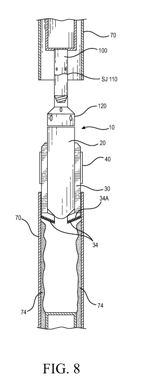
Fig. 8 illustrates one possible application or use of the tapered nose
sections 34. In Fig. 8,
cutting tool 10 is shown in a partially open state: that is, cutter bases 30
are expanded from their
initial, retracted position, but are not at the maximum expansion due to
cutter bases 30 contacting
the inner wall of casing 70. A common situation is one wherein a cement sheath
74 is present on
the inner wall of casing 70, typically as a result of the cementing of a
smaller casing string which
has already been removed from within casing 70. By positioning cutting tool 10
within casing 70
as in Fig. 8, and commencing fluid flow (to expand cutter bases 30 to the
position shown) and
lowering cutting tool 10, tapered nose section 34, along with hardened cutting
surface 34A, can
remove substantially all of cement sheath 74. This enables cutting tool 10 to
be properly
centered within casing 70, and for cutters 40 to cut/mill casing 70 as
desired.
Modification of positioning arms to direct fluid flow
In a presently preferred embodiment, the heel portions 50A of positioning aims
50 are
modified so as to direct fluid flow in a desired direction, depending upon the
operating position
of cutting tool 10. In Fig. 13, cutting tool 10 is in a first, retracted
position, wherein cutter bases
CA 02984427 2017-10-30
WO 2015/168575 PCT/US2015/028821
are retracted. Positioning arms 50 are rotated to the position shown in Fig.
13. Piston 21 is in an
upper position, as fluid flow through bore 26 has not commenced. Piston 21
itself has a bore
21A, through which fluid flows. A seal element 21B (seen in Fig. 12) provides
a seal so as to
force piston 21 downward with fluid flow. Fluid flow through piston bore 21A
may be split as
can be seen in Fig. 13, with a portion flowing substantially straight down
(the Directly Downhole
Flow) and a portion being diverted through flow passages 26C (the Diverted
Portion). As can be
recognized, depending upon the size and shape of heel portions 50A of
positioning arms 50, fluid
flow in a directly downhole direction can be stopped or diminished. In a
preferred embodiment,
the shape of heel portion 50A is modified, whether in the initial manufacture
or post-manufacture
by grinding, etc., to remove the inner corner sections, to produce an angled
surface, depicted as
50B in Fig. 14. As can be understood from Fig. 14, which shows positioning
arms 50 in an
expanded position (i.e. cutting tool 10 is open, as in Fig. 12), a fluid path
substantially directly
downhole and through positioning arms 50 is created, denoted by the circle
50C. This enables
fluid circulation down through the lowermost end of cutting tool 10, which is
particularly
beneficial when cutting with the tapered nose sections 34. Fig. 15 shows the
tool in a closed
position (as in Fig. 13), with positioning arms 50 retracted.
Use of pins to align and guide operating piston, in lieu of alignment blocks
Piston 21 is disposed in bore 26, so as to move longitudinally in the bore in
response to
fluid flow. While piston 21 is aligned in bore 26 to an extent by its shape,
and by seal assembly
21B (which provides a fluid seal around piston 21 in bore 26), additional
alignment is desired for
the smaller diameter section 21D of piston 21. Earlier known designs utilized
alignment blocks
positioned within bore 26. The presently preferred embodiment of the present
invention uses a
pair of pins 21C (only one pin shown for clarity), inserted through holes 21E
in main body 20.
CA 02984427 2017-10-30
WO 2015/168575 PCT/US2015/028821
11
Pins 21C are positioned so as to closely constrain piston 21, and more
specifically smaller
diameter section 21D, from side to side movement. Pins 21C are more easily
fitted, removed and
replaced than arc alignment blocks.
Method of use of the cutting tool
An exemplary method of use of cutting tool 10 with expandable cutter bases 30
can now
be described. A main body 20, cutter bases 30, and positioning arms 50, with
multiple cutters
attached to each cutter base 30, are selected with dimensions appropriate for
the size casing that
is to be cut. A relatively short downhole window is first cut in the tubular
in interest, with a two-
arm casing cutter or conventional cutting tool, or with cutting tool 10 when
configured for that
task. As seen in Fig. 3, a window 72 of sufficient length that cutter bases 30
can fit therein is
generally desired.
The next step is to locate cutting tool 10 within window 72. Although various
methods
are possible, one preferred method is to lower cutting tool 10 to a depth
known to be slightly
below window 72. Fluid circulation is then started, which will move cutter
bases 30 (and cutters
40) outward, into contact with the casing wall. Cutting tool 10 is then pulled
uphole, while
cutters 40 are in contact with the casing wall. When cutting tool 10 is
positioned within casing
window 72 such that the lowermost cutters are above the casing edge, cutter
bases 30 can fully
extend and multiple indicators will be noted at the surface, including a
decrease in drag, change
in pump pressure, decrease in torque, etc. Now, the stabilizing section 32 of
cutter bases 30 will
be positioned against the wall of the casing, and cutters 40 will be
positioned over the casing
edge; this is the position seen in Figs. 3 and 5. Fluid circulation continues
so as to maintain the
proper positioning of the cutter bases and cutters. Rotation of the cutting
tool 10 is commenced,
and a desired amount of weight is applied to the cutting tool, to force the
lowermost cutter edges
CA 02984427 2017-10-30
WO 2015/168575 PCT/US2015/028821
12
against the upward-facing casing edge and consequently commence cutting or
milling of the
casing. It is to be understood that the sequence of steps set forth above is
only one possible
method of use; same may be changed as required, including but not limited to
the sequence or
order of the different operations, additional steps may be added, steps may be
omitted, etc.
Conclusion
While the preceding description contains many specificities, it is to be
understood that
same are presented only to describe some of the presently preferred
embodiments of the
invention, and not by way of limitation. Changes can be made to various
aspects of the
invention, without departing from the scope thereof. For example, dimensions
of the various
components of the tool can be varied to suit particular jobs; the number of
cutter bases can be
varied; the number and positioning of cutters per cutter base can be varied;
size and shape of the
cutters can vary; and methods of use can ye varied.
Therefore, the scope of the invention is to be determined not by the
illustrative examples
set forth above, but by the appended claims and their legal equivalents.