Note: Descriptions are shown in the official language in which they were submitted.
CA 02984442 2017-10-30
WO 2016/176578 PCT/US2016/030119
FILTER ELEMENT WITH MAGNETIC ARRAY
Background of the Invention
[0001] The invention relates generally to filter elements and, more
specifically, to a novel,
non-obvious filter element having a magnetic array for assisting in the
removal of ferrous
particles from a fluid flow.
[0002] In the process of making hydraulic components, such as gears, pumps,
motors, valves
and cylinders, ferrous metal particles are produced that contaminate the
fluids used in the
manufacturing process. These ferrous particles can result in decreased life of
the fluid system.
Current ISO standards require the removal of particles down to the level of 4
microns. Filters
capable of removing particulate contaminants down to 4 microns are expensive
and often must
be combined into a bank of filter elements in parallel or series to handle the
amount of fluid flow
that must be processed. When filtering oil used in manufacturing processes,
magnetic are known
for use in removing ferrous contaminants, including even sub-micron sized
contaminants, from
the fluid flow. Typically, these magnetic filters are a one-time expense and
can be placed
upstream of traditional filter media to help extend the life of the standard
filter, thus reducing
overall costs of operation.
[0003] In operational systems, such as engines, transmissions, and mobile
construction
equipment hydraulic systems, iron based contaminates will be generated in the
normal wear and
tear of operation. Typically, these metal contamination particles are
relatively hard and can
induce wear in a system. Many times these systems are operated outside in cold
environments
and putting in a fine filter medium to trap effectively these fine particles
can have a negative
impact on performance due to the increased pressures from the high viscosity
of low temperature
oil. Therefore, the filters used tend to be higher in absolute micron rating
which allows larger
contaminants to flow through the system and ultimately leads to lower
component life. Magnetic
filters can dramatically improve the filtration of the oil to much finer
filtering without the cold
weather bypass restrictions of a standard filter.
Summary of the Invention
[0004] The present invention is a filter element having a magnetic array
and which is
designed to trap the most abrasive contaminates, which are ferrous based, from
a fluid system
with a low service cost. The filter element has an outer cylindrical can and a
coaxial inner liner
1
CA 02984442 2017-10-30
WO 2016/176578
PCT/US2016/030119
with a plurality of axial magnets extending substantially the length of the
liner interposed in a
cylindrical array either between the liner and the outer can or around the
outer can. In contrast to
known filters, the magnets are thus placed inside the metal can and so are
more effective at
trapping ferrous contaminants, The ferrous based contaminates are attracted to
the liner by the
magnets and held. When it is time to service the magnetic filter, the liner is
removed to either be
washed and reused, or simply thrown away if the liner can be made cheaply
enough. The design
should be modular in nature such that multiple filters can be stacked in
parallel circuits to slow
the flow down to maximize the contaminant removal. In some installations, the
parallel system is
placed in front of the standard filter to act as both an absolute filter as
well as an indicator when
to service the system. Other versions could be made to target specific markets
such as diesel
engines used in transportation and logistics, as well as other markets.
100051 In a preferred embodiment, a spiral baffle is placed inside the
filter to increase the flow
path of fluid through the filter, thereby also increasing residence time in
the filter, and to direct the
higher density contaminants toward the liner at outer wall of the filter where
the magnetic filed is
the strongest and where trapping of the ferrous contaminants is most
effective. An advantage of the
spiral flow path is that it has a constant cross-sectional area which
eliminates restrictions in the
fluid flow path. Alternatively, an insert which induces a vortical flow of the
fluid along the axis of
the filter can be used.
100061 In another preferred embodiment, the magnets are arranged in pairs
of alternating
polarity. Alternatively, they may be arranged in a spaced relationship with
adjacent magnets
having alternating polarity.
100071 In
another preferred embodiment, multiple filter elements of the present
invention
are arranged in series to increase the holding capacity of trapped
contaminants. Alternatively,
multiple magnetic filter elements of the present invention may be arranged in
parallel arrays that
will slow down the fluid flow through each element, thereby increasing the
residence time in
each element to allow more time for trapping of the ferrous contaminants. The
stacked and
parallel arrays can be combined with a filter having standard filtering medium
to catch non-
ferrous contaminants for absolute filtration capability. The standard filter
can then use a pressure
differential detection across the filer medium to indicate when to check the
magnetic array filter
elements for cleaning.
2
CA 02984442 2017-10-30
WO 2016/176578 PCT/US2016/030119
[0008] In another embodiment, an air purge can be used to push fluid out of
the array to
facilitate changing of the filter elements.
[0009] In an alternative embodiment, the stacked arrays of the standard
filter element and the
magnetic array filter elements of the present invention may be assembled in
two parallel circuits
such that one side of the two parallel circuits can be serviced while the
other side remains
operational.
[0010] There is, accordingly, an interest in developing a magnetic arrays
filter element with
more effective trapping characteristics and which can be more easily serviced.
Brief Description of the Figures
[0011] Fig. 1 is a cross-sectional view of a filter element of the present
invention wherein an
insert which induces a vortex in the fluid flow is used.
[0012] Fig. 2 is an exploded view of the embodiment of Fig. 1.
[0013] Fig. 3 is a perspective view of a filter element of the present
invention wherein a spiral-
shaped insert is used to direct the fluid in a spiral flow pattern inside the
filter element.
[0014] Fig. 4 is an exploded view of the embodiment of Fig. 3.
[0015] Fig. 5 is a cross-sectional view of the embodiment of Fig. 3.
[0016] Figs. 6a and 6b are alternative arrangements of magnets of the filter
elements of the
present invention.
[0017] Fig. 7a is a side view of an alternative embodiment of the filter of a
filter of the present
invention; Fig. 7b is a cross-sectional view of the filter of Fig. 7a; Fig. 7c
is a partially exploded
view of the filter of Fig. 7a wherein the outer pressure wall has been removed
to show the
interior of the filter.
Description of the Invention
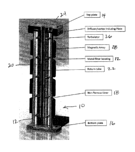
[0018] Illustrated in Figs. 1 and 2, generally at 10, is a preferred
embodiment of a filter
element of the present invention. The filter element 10 includes a cylindrical
filter housing 12 to
which is affixed a top plate 14 and a bottom plate 16. A non-ferrous liner 18
is received in a
close fit inside the housing 12. An insert 20 extends from the top plate 14
axially down the
housing 12, terminating above the bottom plate 16. The insert 20 includes a
central return tube
22. Fluid is directed into the filter element 10 through a port 24 in the top
plate 14 and is
3
CA 02984442 2017-10-30
WO 2016/176578 PCT/US2016/030119
returned to the exterior of the filter element 10 via the return tube 22. The
insert 20 preferably
has a plurality of radially extended plates 26 that act to introduce a flow
pattern to fluid inside
the filter element 10. Encircling the exterior of the filter housing 12 are a
plurality of annular
rings of magnets 28 which will act to attract ferrous contaminants present in
the fluid where they
will be held against the liner 18.
[0019] In certain embodiments, it may be desirable to induce a predetermined
flow pattern of
the fluid inside the filter element 10 so as to improve the filtering
efficiency of the filter element
10. For example, inducing a vortex in the fluid around the longitudinal axis
will increase the
residence time of the fluid inside the filter element 10 and will also cause a
centripetal force that
will urge the higher density ferrous contaminants toward the liner 18 and
arrays of magnets 28.
The vortex can be induced by angling of the port 24 and by selecting a shape
and placement of
the plates 26 that will help maintain the vortical flow.
[0020] Illustrated in Figs. 3 and 4, generally at 110 is an alternative
embodiment of the present
invention filter element. The filter element 110 includes a cylindrical filter
housing 112 to which
is affixed a top plate 114 and a bottom plate 116. A non-ferrous liner 118 is
received in a close
fit inside the housing 112. An insert 120 extends from the top plate 114
axially down the
housing 112, terminating above the bottom plate 116. The insert 120 includes a
central return
tube 122. Fluid is directed into the filter element 110 through a port 124 in
the top plate 114 and
is returned to the exterior of the filter element 110 via the return tube 122.
The insert 120 has
helical fighting 126 to induce a spiral flow pattern to fluid inside the
filter element 110.
Encircling the exterior of the filter housing 112 are a plurality of annular
rings of magnets 128
which will act to attract ferrous contaminants present in the fluid where they
will be held against
the liner 118. The helical fighting 126 acts to increase the residence time of
fluid inside the
filter element 110 and creates a centripetal force that will urge higher
density ferrous
contaminants into proximity of the liner 118 and magnet arrays 128.
[0021] A further preferred embodiment is illustrated generally at 210 in Fig.
5. It is similar to
filter element 110 except that the magnet arrays 228, including individual
magnets 130, have
been placed inside the filter housing 112 but outside the non-ferrous liner
118. By placing the
magnet arrays 228 inside the filter housing 112, any shielding effect of the
filter housing 112 will
be eliminated and the capture of ferrous contaminants improved. If desired, a
plurality of
4
openings can be created in the liner 118, preferably not in the areas of the
magnets 130, to allow
the pressure to equalize on either side of the liner 118.
[0022] The individual magnets 130 may be arranged in at least two different
ways. The
magnets may be arranged in adjacent pairs of alternating polarity, as
illustrated in Fig, 6a and
similar to that described in US Pat. No. 7,662,282, or as individual magnets
spaced apart from
each other with alternate magnets having opposite polarity, as illustrated in
Fig. 6b.
[0023] In certain applications, it may be preferable to provide a port in the
bottom plate 16, 116
through which compressed gas can be directed into the filter housing 12, 112,
to assist in purging
fluid from the filter 10, 110.
[0024] An alternative embodiment is illustrated in Figs. 7a-7c, wherein the
filter is illustrated
generally at 210. The filter 210 includes a filter housing or pressure vessel
wall 212 to which is
affixed a top plate 214 and a bottom plate 216. A non-ferrous liner 218 is
received in a close fit
inside the housing 212. An insert 220 is comprised of a central, closed spacer
tube 222 about
which are arranged in a vertically spaced, stacked relationship a plurality of
spacer plates 224.
Each spacer plate 224 has a partial annular shape wherein a portion of an
otherwise annular piece
of material has been removed, as at 226 in Fig, 7c. The arrangement of the
removed sections 226
alternate from one side of the filter 210 for odd-numbered spacer plates 224
to the opposite side
of the filter 210 for even-numbered spacer plates 224.
[0025] Oil to be filtered is introduced into the filter 210 at inlet 230 and
is removed from the
filter 210 at outlet 232. The path of the oil inside the filter 210 is
determined by the arrangement
of the removed sections 226 of the stacked spacer plates 224. Since the
removed sections 226
alternate sides of the filter 210 as described, the oil is forced to go from
one side of the filter 210
to the other side as it encounters each spacer plate 224. The path of the oil
through the filter 210
is thus increased as is the residence time it spends near the circumferential
periphery of the filter
210. The oil thus has a stepped flow path in contrast to the spiral flow path
of the filter 10. A
series of magnet arrays 228, similar to those described in the other
embodiments are arranged
outside the filter housing 212 and will serve to trap ferrous contaminants
against the non-ferrous
liner 218. An advantage of the embodiment filter 210 is that the stacked
spacer plates can be
easily and inexpensively manufactured, for example, by laser cutting.
Date Recue/Date Received 2022-06-21
CA 02984442 2017-10-30
WO 2016/176578
PCT/US2016/030119
[0026] The foregoing description and drawings comprise illustrative
embodiments of the
present inventions. The foregoing embodiments and the methods described herein
may vary
based on the ability, experience, and preference of those skilled in the art.
Merely listing the
steps of the method in a certain order does not constitute any limitation on
the order of the steps
of the method. The foregoing description and drawings merely explain and
illustrate the
invention, and the invention is not limited thereto, except insofar as the
claims are so limited.
Those skilled in the art who have the disclosure before them will be able to
make modifications
and variations therein without departing from the scope of the invention.
6