Note: Descriptions are shown in the official language in which they were submitted.
CA 02984595 2017-10-31
WO 2016/178208
PCT/1L2016/050401
- 1 -
SYSTEM AND METHOD FOR MOBILE COMMUNICATION THROUGH
GEOSTATIONARY SATELLITES
TECHNOLOGICAL FIELD
The present invention is in the field of communication devices and methods.
The
invention relates to satellite based mobile communication systems.
BACKGROUND
Mobile communications systems have been widely used in the past few decades.
Pluralities of cellular communication servers are deployed in populated
regions around
the world, and thus provide a global communication network. However, such
cellular
communication systems are limited to regions where suitable servers and
antennas are
deployed.
In various situations, reliable communication is required even at remote
locations where no cellular antennas are present at a distance which would
enable
reception. Telephonic communication through satellites allows a user to be
located
almost at any corner of the globe while being available for incoming calls, or
capable of
making outgoing calls. Current commercially available mobile satellite phones
utilize
communication through dedicated low-orbit satellites allowing global coverage
and
efficient communication with low gain transmission systems.
Well known is the Iridium Inc. satellite communication system which utilizes
66
active satellite units, as well as additional "spare" units for use in case of
failure of one
or more of the active satellites. The satellites are located in low orbit to
allow
communication with handheld mobile devices of relatively small dimensions. The
Iridium communication system utilizes several additional inactive satellites
located in
orbit. These satellites are used as spares to provide coverage in case of
failure of one or
more of the active satellites.
CA 02984595 2017-10-31
WO 2016/178208
PCT/1L2016/050401
- 2 -
Other satellite phone devices require high gain antennas for reliable
communication through satellites in orbit. For example, U.S. Patent No.
6,023,242
describes an Earth station having an antenna configured to establish
communication
with a satellite. The Earth station stores a table of satellite position data
for a plurality of
satellites and is configurable to enable its own location position on the
surface of the
Earth as well as the azimuth and elevation of its antenna to be obtained. The
tabulated
satellite position data is then utilized to calculate the position of the
satellite in relation
to the location position. Thereafter at least one of the satellites is
selected with which to
establish communication and in response to the selection and the obtained
azimuth and
elevation, a direction is determined in which to configure the antenna for
operation with
the at least one selected satellite. Following determination of the direction,
the antenna
is configured for operation with the at least one selected satellite. The
location position
and the azimuth and elevation of the antenna may be determined through the
Earth
station comprising a GPS receiver. The Earth station may be configured as a
mobile,
portable or fixed unit and the invention is configurable to enable
communication to be
established with geostationary satellites, non-geostationary satellites or a
combination
of both geostationary and non-geostationary satellites.
GENERAL DESCRIPTION
There is a need in the art for a novel technique and system for use in mobile
communication while providing effective global coverage. Moreover, there is a
need for
a handheld mobile satellite communication device suitable for providing
reliable
communication while it moves, as well as providing sufficient operation time
utilizing a
mobile power supply.
Currently existing mobile satellite communication systems utilizing dedicated
satellites require high investment in deployment of satellites in orbit for
sufficient
coverage, as well as periodic maintenance and satellite exchange in case of
malfunction.
Alternatively, communication systems utilizing geostationary satellites are
typically
large, high on energy consumption and require proper orientation for
communication
through geostationary satellites. These requirements greatly reduce mobility
of the
communication system. It should be noted that, and as generally known, a
mobile
communication system is generally described as a system allowing continuous
CA 02984595 2017-10-31
WO 2016/178208
PCT/1L2016/050401
- 3 -
communication even while it moves. This is contrary to a portable
communication
system, which although it can be moved, requires to be stationary for proper
operation.
The inventors of the present invention have found that to provide a compact,
mobile and efficient communication system capable of transmitting data through
suitable satellites and generally through geostationary satellites, a proper
tradeoff should
be addressed between transmission and reception gain and communication bit
rate. The
satellite communication system of the invention is generally configured to
provide light,
energy efficient and a mobile device for voice and data communication with an
appropriate hub through one or more satellites. Preferably, the communication
device
may be in suitable dimensions to be handheld, while providing bilateral
communication
from effectively every location on the globe. The device may comprise one or
two
antenna units suitable for receiving input signals arriving from a satellite
as well as
transmitting output data to such a satellite. The antenna unit(s) is/are
connected to a
modem unit, which in turn is connected to a processor unit configured and
operable for
operating the device in accordance with a user generated operation profile.
Typically,
the device may also comprise a power storage unit, e.g. a battery, while
additionally or
alternatively, the device may be connectable to an external power supply. It
should be
noted that the technique of the present invention may me used for
communication
through geostationary satellites as well as other orbiting satellites having
predetermined
known trajectory. For simplicity the technique of the invention is described
herein
below as referring to geostationary satellites, however it should be
understood that non
geostationary satellites may also be used. More specifically, as a
geostationary satellite
has a fixed location relative to a given point of the surface of the earth,
any other
satellite may be used, given a known trajectory relative to a given point on
the surface
of the earth.
To provide the desired small form factor, as well as to allow communication
through a geostationary satellite, the antenna unit(s) may preferably be
configured as
phased array antenna unit(s). Such a phased array antenna unit comprises an
array of
antenna elements configured to transmit signals with appropriately tailored
phase
difference between them, thus providing electronic beam steering for
transmitted
signals. Additionally, the phased array antenna unit allows for selectively
collecting
input signals arriving from desired directions. To this end, proper phase
relations
applied to input data collected by the different elements of the array act as
amplification
CA 02984595 2017-10-31
WO 2016/178208
PCT/1L2016/050401
- 4 -
to signals having similar phase relations when arriving to the antenna
elements and
allow resolving of the desired collected signals.
The processor unit may comprise several modules, being hardware and/or
software modules, configured and operable to communicate between the modules
and
with the one or more antenna units and the modem unit. The processor may also
be
configured to provide suitable input and output connections to allow user
operation such
as setting preferences, initiating call or data transfer etc. Specifically,
the processor unit
comprises at least an antenna orientation optimizer module and a network
registration
module. The antenna orientation optimizer module is generally configured and
operable
to control phase variations between the different antenna elements of the
phased array
antenna units. Such phase variations indicate appropriate direction (e.g.
azimuth and
elevation) for transmission and reception of signals. The network registration
module is
configured and operable for registering the system to a network provided by a
suitable
hub communicating through a satellite.
It should be noted that as the device may change its location with time, the
satellite selected for communication may vary. To support mobile satellite
communication, one or more hub terminals, configured for maintaining the one
or more
communication networks, may be used. The hub terminal(s) is/are generally
configured
to provide a stable communication path with a plurality of geostationary
satellites and
thus provide communication to mobile devices. The hub terminal(s) may also be
connected to one or more ground communication networks such as one or more
cellular
networks and/or the Internet, to provide external communication.
Each hub terminal may be configured for supporting a predetermined number of
mobile systems within a region covered by transmission of a single satellite.
To this
end, the hub terminals may be configured to provide continuous beacon
transmission in
at least a dedicated common control channel, as well as supporting a
predetermined
number of private communication channels to be assigned to operating mobile
systems/users upon registration. Generally, each of the private communication
channels
is defined by a pair of downlink and uplink frequencies, where the downlink
frequency
is used for transmission from the hub through the corresponding satellite and
to a
mobile system, and the uplink frequency is used for transmission from the
mobile
system through the satellite to the hub.
CA 02984595 2017-10-31
WO 2016/178208
PCT/1L2016/050401
- 5 -
To provide optimized communication with a small form factor antenna unit, the
technique of the invention may utilize a dual alignment process. In this
connection a
mobile system may be configured to establish modem synchronization by a first
coarse
alignment based on a common control signal transmitted by a network hub. When
initial
synchronization is achieved, a close loop alignment may be used for tuning of
the
antenna alignment and improving communication quality. Thus, for the initial
alignment, a first low data rate is used, utilizing high efficiency error
correction
techniques at the cost of data transmission rate. When synchronization is
achieved, data
transmission may generally include data about direction of transmission and
the hub
may generally send corresponding data on quality of communication. This thus
allows
tuning of alignment in fine scanning, as well as the use of conical scanning
techniques,
to maintain synchronization while the system is moving. The data rate at this
stage may
be increased as synchronization is achieved, and, in active mode, a second,
higher data-
rate may be used.
Thus, according to one broad aspect of the present invention there is provided
a
system for satellite communication comprising:
(a) one or more antenna units configured for receiving and transmitting
electromagnetic radiation at one or more frequency ranges;
(b) a modem unit connected to the one or more antenna units and configured
for modulating input signals received by said one or more antenna units to
electronic
data and modulating output electronic data to signals in one or more
predetermined
frequency ranges to be transmitted by said one or more antenna units;
(c) a processor unit connected to said one or more antenna units and to
said
modem unit, the processor unit comprising:
i) antenna orientation
optimizer module configured and operable for
varying at least one of azimuth and elevation of signal transmission and
reception of said one or more antenna units; and
ii) network
registration module configured and operable for
registering the system to a communication network, said registering
comprising:
selecting a free private communication channel from a list of free channels
provided by the network, generating a signal comprising a selected sequence
for
transmission to a hub through the satellite, and configured and operable to be
CA 02984595 2017-10-31
WO 2016/178208
PCT/1L2016/050401
- 6 -
responsive to an appropriate notification signal from the hub in said private
communication channel.
Generally, the system may be configured for communication through a
geostationary satellite.
According to some embodiments, the antenna optimizer module may be
configured and operable for further varying polarization of signal
transmission and/or
reception of electromagnetic radiation by said one or more antenna units.
Typically said one or more antenna units may comprise at least a transmitting
phased array antenna and a receiving phased array antenna. The antenna
orientation
optimizer module may be configured to vary phase relations between antenna
elements
of the transmitting phased array antenna units and vary phase relations
between antenna
elements of the receiving phased array antenna units to thereby direct
orientation of
transmission or reception of electromagnetic radiation signals by said
transmitting and
receiving phased array antenna units.
According to some embodiments, the processor unit may further comprise an
initializing module, wherein the initializing module is configured and
operable for
detecting common control signals from a network. Said detecting comprises:
identifying
available regional hub stations from a predetermined list of network hub
stations,
locating at least one satellite associated with at least one of said available
regional hub
stations, determining data about corresponding direction and frequency of a
common
control channel, and providing said direction and frequency data for each of
said at least
one satellite to the antenna orientation optimizer module and providing the
frequency
data to the modem unit with an indication of said frequency for a
corresponding
received signal in said common control channel. Additionally, the processor
may be
configured and operable to wait for a corresponding indication signal received
from the
network. The initializing module may be configured to repeatedly select a
network and
corresponding common control channel until said corresponding input signal is
detected.
The modem unit may be configured and operable to be responsive to a preamble
beacon signal and to adjust frequency of input signals in accordance with data
received
in said preamble beacon signal. Additionally or alternatively, the modem unit
may be
configured and operable for generating a notification signal indicating said
processor
unit when synchronization to a common control channel is achieved. The
processor unit
CA 02984595 2017-10-31
WO 2016/178208
PCT/1L2016/050401
- 7 -
may also be configured and operable for generating a notification signal
indicating the
network registration module when proper indication about synchronization is
received
from the modem unit.
The initializing module may further be configured to extract from the received
common control signal a list of available private channels for communication
through
the network and to inform the network registration module. The network
registration
module may be configured for selecting a free private communication channel
from said
list of available private channels and to direct said antenna orientation
optimizer module
for aligning transmission and reception directions of said one or more antenna
units
accordingly. The network registration module may be further configured and
operable
to be responsive to input signal in said free private communication channel
indicating
availability of said selected free private communication channel.
Additionally or alternatively, the network registration module may be
configured for selecting the signal sequence, and for indicating the modem
unit for
repeatedly transmitting said selected sequence through a free private
communication
channel selected from said list of available private channels. The network
registration
module may also be configured and operable to respond to input communication
from
said hub, which is indicative of said selected sequence and data on quality of
transmission. The selection of a free private communication channel may be
random
selection. Additionally, the network registration module may be configured for
repeating said random selection in accordance with appropriate indications
from the
processor unit.
According to some embodiments, the system may be configured for selectively
operating in either idle mode or active session mode, such that when operating
in idle
mode the modem unit operates to transmit spread signals at a first data rate,
when
operating in active mode the modem is operating for transmitting signals at a
second
higher data rate. The first data rate may comprise spreading of output
transmitted
signals; additionally or alternatively the first data rate may be below 5Kbps.
This may
be used to allow high efficiency error correction on input and output signals
at both
ends of the communication (i.e. at the system end and/or at the hub end). The
second
data rate may be between 10Kbps and 200Kbps and at time between 10Kbps and
500Kbps, e.g. to support voice communication and certain levels of data
communication.
CA 02984595 2017-10-31
WO 2016/178208
PCT/1L2016/050401
- 8 -
The processor unit may be responsive to input data indicative of a request for
engaging an active data session to thereby operate the system in active mode.
The
processor unit may also be responsive to proper indication received through
the
network. To this end the network registration module may be configured and
operable
to be responsive to an input signal indicative of a request for initializing
active session
mode and to provide a corresponding indication to the processor unit.
According to some embodiments, the antenna orientation optimizer module may
be configured to vary at least one of the azimuth and elevation for
transmission and
reception directions of said one or more antenna units in accordance with data
on
location and orientation of the system. To this end, the system may further
comprise one
or more location and orientation sensors configured to provide location and
orientation
data on the one or more antenna units, and provide such location and
orientation data to
the processor unit. Such one or more location and orientation sensors may
comprise at
least one of the following: mechanical compass, electronic compass, one or
more
accelerometers, GPS.
According to yet some embodiments, the antenna orientation optimizer module
may be configured to vary azimuth and elevation of transmission and reception
of said
one or more antenna units in accordance with data about satellite locations.
The system
may further comprise a storage unit, said storage unit comprising data about
satellite
locations and corresponding communication networks.
It should be noted that according to some embodiments of the invention, the
system may comprise local input and output connection modules configured for
local
communication with an external electronic device for data exchange over said
network.
For example, the system may allow a user to initiate and handle communication
sessions utilizing an external handheld electronic device (e.g. Smartphone,
personal
computer or any other type of handheld communication device having proper
communication capability).
According to one other broad aspect of the invention, there is provided a
method
for use in satellite communication, the method comprising:
(a) providing data on location of a satellite and data on a frequency range
of
a common control channel transmitted through said geostationary satellite;
(b) applying a
corresponding phase pattern to input data received from a
phased array antenna in said frequency range to detect a beacon signal in said
input data
CA 02984595 2017-10-31
WO 2016/178208
PCT/1L2016/050401
- 9 -
and detect a common control signal provided by a network hub in said common
control
channel through said geostationary satellite; and
(c)
synchronizing communication with the hub on said common control
channel.
According to some embodiments, said satellite is a geostationary satellite.
According to some embodiments, the method may further comprise verifying
said synchronizing to the common control channel, and selecting an additional
communication frequency upon identifying that said synchronizing has failed.
Additionally or alternatively, the method may further comprise processing said
common control signal to determine a list of available private communication
channels,
selecting one of said available private communication channels for registering
to the
network hub through said selected private communication channel. Said
selecting one
of said available private communication channels may be a random selection.
According to some embodiments, said registering to the network hub may
comprise: applying a phase pattern to the phased array antenna for receiving a
downlink
beacon signal in a downlink frequency of said selected private communication
channel;
calibrating a transmission phased array antenna in accordance with the
determined
phase pattern and transmitting a registration signal in an uplink frequency of
the private
communication channel to enable completion of the registration upon receiving
an
acknowledgement signal indicating registration. Generally, transmission of
said
registration signal may utilize a spread transmission rate.
According to some embodiments the method may determine whether the
registration is complete, and selecting one other private communication
channel for
registering, upon identifying that the registration has failed.
The method may further comprise selectively transmitting an active session
request for establishing a direct communication link with said hub.
Location data may be repeatedly provided, to determine variations in data on
location of said satellite and for periodically synchronizing to said common
control
channel. The location data may be provided by reading data on location and
direction of
orientation from one or more location and orientation sensors comprising at
least one of:
GPS, accelerometer, magnetic compass, electronic compass.
According to some embodiments, the method may comprise repeatedly varying
the phase pattern to the phased array antenna around said location data for
detecting
CA 02984595 2017-10-31
WO 2016/178208
PCT/1L2016/050401
- 10 -
relative movement of the phased array antenna with respect to said
geostationary
satellite.
According to yet another broad aspect of the invention there is provided a
program storage device readable by machine, tangibly embodying a program of
instructions executable by the machine to perform a method for use in
satellite
communication, said method comprising:
= providing data on location of a geostationary satellite;
= providing data on communication frequency of a common control
channel through said geostationary satellite;
= applying a corresponding phase pattern to input data received from a
phased array antenna to detect a beacon signal and detecting a common control
signal
provided by a network hub through said geostationary satellite; and
= synchronizing to said common control channel.
According to yet another broad aspect of the invention there is provided a
computer program product comprising a computer useable medium having computer
readable program code embodied therein for use in satellite communication, the
computer program product comprising:
computer readable program code for causing the computer to provide data about
location of a geostationary satellite;
computer readable program code for causing the computer to provide data about
communication frequency of a common control channel through said geostationary
satellite;
computer readable program code for causing the computer to apply a
corresponding phase pattern to input data received from a phased array antenna
to detect
a beacon signal and detecting a common control signal provide by a network hub
through said geostationary satellite; and
computer readable program code for causing the computer to synchronize to said
common control channel.
BRIEF DESCRIPTION OF THE DRAWINGS
In order to better understand the subject matter that is disclosed herein and
to
exemplify how it may be carried out in practice, embodiments will now be
described,
CA 02984595 2017-10-31
WO 2016/178208
PCT/1L2016/050401
- 11 -
by way of non-limiting example only, with reference to the accompanying
drawings, in
which:
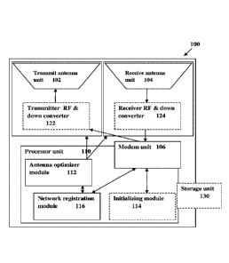
Fig. I schematically illustrates a mobile communication system according to
embodiments of the present invention;
Fig. 2 illustrates a communication initiating process according to some
embodiments of the invention;
Fig. 3 illustrates the step of a registration process according to some
embodiments of the invention.
DETAILED DESCRIPTION OF EMBODIMENTS
As indicated above, the present invention provides a mobile communication
system for transmitting and receiving data through one or more satellites.
Reference is
made to Fig. 1 schematically illustrating a system 100 for use in satellite
based
communication according to the present invention. The system 100 includes one
or
more antenna units; two such antenna units 102 and 104 are shown, at least one
modem
unit 106 and a processor unit 110. The system 100 may generally also include
storage
unit 130, or be connectable to such storage unit, a power supply unit, and one
or more
utilities for local input and output, which are not specifically shown in the
figure.
The one or more antenna units are configured for receiving and transmitting
electromagnetic radiation at one or more predetermined frequency ranges.
Generally,
the system may utilize two antenna units 102 and 104 as exemplified in the
figure. The
antenna units may be selected such that a first antenna unit, e.g. 102, is a
dedicated
transmitting antenna and a second antenna unit, e.g. 104, is a dedicated
receiving
antenna. Additionally, as shown in the figure, the antenna units may be
configured as
antenna elements being connected to corresponding RF and converter units 122
and
124. The RF and converter units 122 and 124 may be configured for extracting
RF
signals from the suitably modulated input signal received by the antenna
and/or
modulate a signal to be transmitted on a carrying frequency for appropriate
transmission. For example, in the receiving antenna unit 104 the RF and
converter unit
124 may include a low noise RF amplifier and a down converter unit. In the
transmitting antenna unit 102 the RF and converter unit 122 may include a
power
amplifier and an up converter unit.
CA 02984595 2017-10-31
WO 2016/178208
PCT/1L2016/050401
- 12 -
The antenna unit(s) is/are connected to a modem unit 106, which is configured
for de-modulating input signals to electronic data to be processed by the
processor unit
110 as well as to receive output electronic data from the processor unit 110
and generate
(modulating) corresponding signals for transmission by the antenna units. The
modem
unit 106 may or may not be a part of the processing unit 110 in accordance
with
structural design of the system 100.
The processor unit 110 is connected to the one or more antenna units 102 and
104 and to the modem 106 and is configured and operable for operating the
antenna
units to transmit and receive signals corresponding to various network
activities, as well
as communicating over the network. Such network activities generally include
identifying a satellite that provides a suitable communication network;
setting the
antenna unit with appropriate direction for reception and for transmission of
signals to
and from the satellite; identifying network ID; registering to an available
network; and
responding to or engaging in active communication sessions through the
network. To
this end, the processor unit may generally include at least an antenna
optimizer module
112 and a network registration module 116. It should be noted that the
processor unit
110 may include one or more additional modules such as initializing module 114
(shown in dashed lines) and other modules that are not specifically shown. It
should
also be noted that the modules may be hardware or software operation modules
and may
be embodied in one or more physical processing elements defining together the
processing unit 110.
The antenna orientation optimizer module 112 is configured and operable for
varying azimuth and elevation, and in some embodiments also polarization, for
transmission and reception of said one or more antenna units. In this
connection it
should be noted that, the one or more antenna units 102 and 104 are preferably
phased
array antenna units. Generally, phased array antenna is configured from an
array of
antenna elements operable for transmission/reception of electromagnetic (EM)
signals,
such that different elements of the array are operated with small phase
difference with
respect to other elements of the array. Appropriate control on the phase
relations
between different elements of the antenna array provide control over direction
of
transmission of EM signals (or direction from which a signal is received).
Generally, the
technique of the present invention allows the use of small form factor phased
array
antenna units by providing registration protocols allowing low gain
transmission and
CA 02984595 2017-10-31
WO 2016/178208
PCT/1L2016/050401
- 13 -
reception elements. In this connection it should be noted that data
transmission utilizing
low gain antenna units might generate data transmission errors and increase
synchronization time. The technique of the present invention utilizes relative
low data
rate of communication (e.g. a few hundreds of bits per second up to a few
kilobits per
second) for initialization and registration. This is while the systems, as
well as the
network hub, are configured to switch into active mode and communicate with
relatively higher data rate (e.g. tens to hundreds of kilobits per second).
More specifically, and as will be described in more detail further below, the
technique of the invention allows dual mode communication, wherein, in idle
mode, the
system is configured to transmit and receive data bits at a lower bit-rate,
allowing the
use of various error correction techniques and thus enabling synchronization
utilizing
low received signal power, herein referred to as low gain synchronization.
When an
active communication session is initiated, either by a user or by receiving an
appropriate
request from the hub (e.g. incoming call), the system and the hub are
configured to
communicate at a higher data-rate utilizing the synchronization already
achieved in the
registration. Generally the system may utilize various tracking techniques,
such as
conical scan, to maintain communication while in active communication mode.
In this connection, the network registration module 116 is configured and
operable for registering the system to a network provided by a corresponding
hub
through a satellite. The registration process generally includes selection of
an
available/free private communication channel and transmitting a signal formed
by a
selected sequence to the hub and being responsive to an appropriate
notification from
the hub that registration is complete. Generally, the mobile communication
system 100
is configured for periodically registering to the network provided in the
corresponding
region. This allows the system to receive indication of incoming data
transmission
sessions such as an incoming telephone call, short text message, email or any
other data
transmission session. Additionally, registration to the network is needed to
initiate a
data transmission session, such as an outgoing telephone conversation, sending
short
text messages, emails or any other outgoing data transmission session. In this
connection, and as indicated above, communication for registering to the
network may
generally be transmitted (by the system and by the hub) at a relatively low
data-rate.
More specifically, the registration signals, including downlink beacon and
request to
connect to a private channel, may be transmitted in a spread signal/spread
spectrum
CA 02984595 2017-10-31
WO 2016/178208
PCT/1L2016/050401
- 14 -
technique and in 1:4 to 1:10, and at times to 1:50 or 1:100, or generally
below 1:1000,
such data spreading ratios enabling high error correction and fast
synchronization.
Additionally, according to some embodiments, the processor unit 110 may
further include an initializing module 114. The initializing module is
configured and
operable to be responsive to a common control signal (CCS) associated with a
network
hub. Such a common control signal may be continuously transmitted by every
network
hub, at a predetermined corresponding frequency channel, designated as a
common
control channel (CCC), and may include data indicative of the specific network
(network identifier) and data on available private communication channels.
Generally
the CCS may include additional data such as time indication provided to assist
mobile
communication systems in calibration. Thus, the initializing is generally
configured and
operable to determine available regional hub stations, operating through
satellites that
are in communication range, and provide information indicative of location of
the
corresponding satellites and their associated CCC's to the antenna optimizer
module 112
and the modem unit 106 respectively. As indicated above, the antenna optimizer
module
112 is configured for determining proper direction (azimuth and elevation)
from which
the CCS is to be detected, and optimizes the receiving antenna unit 104
accordingly.
The antenna optimizer module 112 together with the modem unit 106 is also
provided
with the frequency of the CCC to extract the CCS from input radiation received
by the
antenna unit 104. It should be noted that a list of global satellite locations
and network
hubs may be preinstalled in the system 100 (e.g. in a storage unit 130) and
may be
updated periodically.
As indicated, the system 100 of the present invention is preferably configured
to
be a mobile system, having a relatively small form factor. The system 100 may
be
configured to be in the form of a handheld device having physical dimensions
of a few
centimeters. To provide such a small form factor, the system 100 is preferably
configured with small form factor phased array antenna units, e.g. having
dimensions
within a range between 50mmX5Omm and 130mmX130mm for a receiving antenna 104
unit and similar dimensions for the transmit antenna unit 102. To this end,
the phased
array antenna units may be configured by a 4X4, 5X5, or 6X6 antenna element,
or any
combination of NXM where N and M are between 4 and 25 or between 4 to 16 or
further
between 4 and 12, or generally below 33X33.
CA 02984595 2017-10-31
WO 2016/178208
PCT/1L2016/050401
- 15 -
In this connection it should be noted that the number of elements in a phased
array antenna unit may determine stirring characteristics of the antenna unit.
Generally,
a large number of antenna elements in a phased array antenna unit results in
the
antenna's ability to provide a narrow beam of transmission (or reception), and
thus to
support higher gain. The use of phased array antenna units with a reduced
number of
antenna elements according to the present invention allows, on the one hand, a
low form
factor system configuration that is suitable for mobile use, while it requires
a
communication method suitable for establishing and maintaining communication
utilizing low gain receiving/transmitting antenna units. Additionally, the use
of a
reduced number of antenna elements in the phased array antenna unit results in
a wider
beam (wide angular field for transmitting and receiving) and thus reduces the
required
precision for directing the antenna to the desired satellite for proper
communication.
It should also be noted that according to some embodiments, the antenna unit
may be operated utilizing only a portion of the radiating/receiving antenna
elements.
More specifically, if a phased array antenna unit includes 10X10 antenna
elements, only
one out of four elements is used to provide an array of 5X5 elements. This
enables to
further broaden the angular distribution of the transmitted/received radiation
to thereby
simplify detection of satellite location (at the cost of increased noise and
reduced gain).
Thus, the technique and system as described herein utilizes a registration
process
tailored to provide reliable communication while utilizing mobile, small form
factor
antenna units. The communication technique is designed to eliminate, or at
least
significantly reduce the need for accurate calibration of the antenna units
with respect to
temperature variations, which are generally known to vary transmission
properties and
appropriate phase relation in common phased array antenna units. To this end,
the
system and technique of the invention are generally designed to operate at a
relatively
low bit-rate for providing mainly voice communication; however they may also
be used
for data communication, such as short text messages, email messages and
various other
data types for communication. Generally, the communication network and the
mobile
satellite communication system may be configured to support communication
through
geostationary satellites at a bit rate of between 10Kb/s to 200Kb/s or up to
500Kb/s.
Generally, the use of a relatively low bit rate for communication allows for
improving
antenna and receiver sensitivity, and thus enables the system to establish
reliable
communication using limited gain antenna units. This in turn allows the use of
small
CA 02984595 2017-10-31
WO 2016/178208
PCT/1L2016/050401
- 16 -
form factor antenna units and providing a mobile communication system.
Additionally,
as sensitivity of reception both at the system/terminal side and at the hub
side, allows
for transmission with reduced energy, it thus enables to utilize a battery
type power
supply unit. It should be noted that, as generally known in the art, the
satellite itself does
not take an active part in the communication, other than receiving the input
signal,
amplifying the signal and transmitting the amplified signal.
In this connection, reference is made to Figs. 2 and 3 schematically
illustrating
initialization and registration processed according to the presently described
technique.
As indicated above, the registration processes may generally be performed
periodically
by the system to provide continuous communication with a suitable network and
be
responsive to input communication sessions, i.e. to be available to incoming
calls.
Fig. 2 illustrates an initializing process, which may be performed upon system
start up or after loss of communication. To initialize connection to a
network, data about
location of the system 2001, as well as data about regional networks and
satellites 2002,
is generally provided. The location data may utilize GPS based location as
well as any
other location technique. The location data is used to select a geostationary
satellite
such that the system is located within transmission range thereof. The data on
regional
networks may generally be stored in a storage unit of the system and may be
updated
periodically if needed. The data on regional networks and satellites may
generally
include location of geostationary satellites used by suitable communication
networks as
well as frequency channels of the Common Control Channel corresponding to the
networks. Based on the location of the system, network information and
satellites
providing the network within range, the regional hub base station and
corresponding
common control channel (CCC) are determined 2004. The corresponding frequency
is
selected 2006 such that the received antenna unit and the modem unit are set
to the
corresponding frequency 2008. Generally, according to some embodiments, the
CCC
frequency, as well as additional communication channel frequencies, is
selected to be
within frequency range of at least one of the Ku band, K band and Ka band,
i.e. within
the range of 12GHz to 18GHz (Ku band); 18GHz to 27GHz (K band); and 26.5GHz to
40 GHz (Ka band) as defined by the Institute of Electrical and Electronics
Engineers
(IEEE).
In addition to setting the input frequency, the antenna unit is generally set
to
receive input signals coming from the general direction of the selected
satellite 2010.
CA 02984595 2017-10-31
WO 2016/178208
PCT/1L2016/050401
- 17 -
The direction from which signals transmitted from the corresponding satellite
arrive
may be set by providing appropriate phase relations to input EM radiation
detected by
different antenna elements of the phased array antenna unit. Such phase
variation
corresponds to azimuth and elevation of the satellite with respect to the
system. To this
end, the phase variation may be determined by scanning input EM signals with
possible
phase variations to detect maximal signal at the CCC frequency. Alternatively,
an
estimated phase relation corresponding to the satellite location may be
applied, and
varied slightly to maximize signal detection. Such estimated phase relation
may be also
determined in accordance with orientation of the system, which in turn may be
determined by one or more accelerometers. Thus, in some embodiments, the
azimuth
and elevation may be determined in combination with a search for the CCC
signal 2012,
while in some other embodiments, an estimated phase relation corresponding to
the
azimuth and elevation may be determined, and varied to detect the CCC signal
2012. It
should be noted that during initial search for input signal, the phase
variations applied to
the antenna unit (e.g. by the antenna optimizer module) may be coarse
variations. For
example, such initial phase variations may correspond to angular variation of
2-10
degrees for each scanning step. It should also be noted that the use of a
limited number
of antenna elements in the phased array antenna units results in a relatively
wide
angular field of reception, and thus enables such a coarse search.
At this stage, the modem unit attempts to lock on to the detected CCC signal
2014. Such locking may be defined by successful extraction of network data
from the
received signal 2022. However, in some embodiments, the CCC signal may include
sufficient bits for data reconstruction such that a lock may be determined
before the
corresponding data is extracted. Generally, even when the modem unit is locked
on the
CCC signal, a scan for the exact location of the corresponding satellite, i.e.
effective
source of the signal, may continue. This is to enable mobile communication and
to
prevent interruption due to changes in location/orientation of the system.
Specifically, if
the initial scan for the CCC signal is relatively coarse, the ongoing scan
between
modem sync to the end of the communication session may be finer. Such a fine
scan
may include an ongoing conical scan and phase variation corresponding to less
than 2
degree beam variation. If the modem fails to lock on to the CCC signal, the
azimuth and
elevation for CCC detection may be adjusted 2016; a new network, providing a
different CCC may be selected 2018; or a failure to connect notification may
be
CA 02984595 2017-10-31
WO 2016/178208
PCT/1L2016/050401
- 18 -
provided 2024. The selection of a suitable action in case of failure may be
determined in
accordance with a suitable counter 2020 used to determine the number of
attempts to
connect. Generally, at a first failure, as well as a predetermined number of
initial
failures, the phase relations (corresponding to azimuth and elevation) may be
varied to
compensate change in conditions of the antenna or wrong initial estimation of
the
parameters. When a predetermined number of attempts to locate the signal are
unsuccessful, a different network may be sought, providing CCC at a different
frequency. If no signal is detected after repeated attempts, a suitable
notification may be
provided, such as a "no service" notification, indicating that no satellite
reception is
detected.
The registration to a communication network is generally a periodic process
required to maintain connection and be responsive to incoming communication
sessions. Reference is made to Fig. 3 exemplifying the registration process
according to
some embodiments of the present invention. The registration is generally
performed
based on network data such as satellite location and communication channels'
frequency
bands. Such data may be provided through the CCC signal of the network. The
list of
private channels, generally listing the available private channels is provided
3001. This
list may preferably be extracted from the CCC signal; however in some
embodiments,
data indicating the list of private channels may be stored in a storage unit
of the device.
From the list, a certain available communication channel is selected 3003.
Typically, to
avoid double selection, where two different systems are trying to register
through the
same channel simultaneously, the selection may be random. However, alternative
algorithms for selection may be used.
After selecting a private communication channel, the modem and receive
antenna unit are set for receiving input signals at the selected frequency
3005. It should
be noted that generally a private communication channel includes a down link
frequency, used for transmission from the hub through the satellite to the
mobile
communication system, and an uplink frequency, used for transmission from the
mobile
device through the satellite to the hub. Thus, the receive antenna is set for
detection of
input signals at the downlink frequency of the selected channel to detect a
downlink
beacon signal 3009. The downlink beacon signal is continuously transmitted by
the hub
in each available private communication channel to identify the availability
of the
channel and assist communication systems in registration to the network.
Before
CA 02984595 2017-10-31
WO 2016/178208
PCT/1L2016/050401
- 19 -
transmission, the modem should preferably be locked on the downlink beacon
2011. If
no lock is achieved, the channel may already be used by a different system, or
the
antenna unit may not be set correctly. To simplify operation, a different
channel may be
selected (e.g. randomly) and a search may be performed for a beacon signal at
a
different downlink frequency. It should be noted that by setting the antenna
unit to a
selected frequency, the phase relations between phased array antenna elements,
when
such an antenna is used, may be changed accordingly. Additionally, change in
location
of the system may be used to continuously update relative azimuth and
elevation of the
satellite with respect to the system. In this connection, an initialization
process, as
described above, may be used periodically.
Once the downlink beacon is detected, the transmitting antenna may be set to
the
uplink frequency of the selected channel 3013. This may generally include the
uplink
frequency together with phase relation in accordance with the relative
direction for
transmission. An uplink beacon may be transmitted to establish communication
with the
hub 3015. The uplink beacon includes a registration sequence, which may
generally
include a selected sequence identifying the system, and preferably includes a
randomly
selected sequence. Additionally the uplink beacon may generally include the
transmission direction, i.e. the current phase relations between antenna
elements of the
phased array antenna units. This is to establish a closed loop calibration
cycle with the
hub to optimize direction for transmission.
Generally, upon receiving such registration sequence, the network hub
identifies
that transmitting system transmits the same registration sequence back to the
system in
the downlink channel 3017. The hub may add to the returning sequence, data on
the
strength of the received signal, as well as network data such as indication
about a
waiting communication or an invitation to initiate a communication session
(e.g.
incoming telephone call etc.). The return signal may be used for further
optimizing the
direction for transmission and reception as well as to enable communication
while the
system is mobile and moving. The process may generally require indication that
the
acknowledgement signal is received 3019. If no acknowledgment signal is
received, a
different private channel may be selected 3025. This may be because a
different system
is trying to register on the same channel, or that transmission is interrupted
for other
reasons. When the acknowledgement signal is received, it is processed to
determine if
any additional information is included, inviting initiation of an active
session 3021. If
CA 02984595 2017-10-31
WO 2016/178208
PCT/1L2016/050401
- 20 -
such information is received, an active communication session may be initiated
3027.
Alternatively, if no specific information is received, the registration
process is over and
the private communication channel is released 3023.
A substantially similar registration may be applied when a user initiated
active
session is requested. In this case, the uplink beacon may include a request
for initiating
an active session in the selected private channel. In this connection, it
should be noted
that transmission of data in the private communication channels may be
provided in
either an idle mode or active mode. The idle mode includes registration as
described
above, and is characterized by signal transmission in a first, lower, bit-rate
to preserve
power and to provide higher gain and assist in detection of the network. This
is while in
the active mode, data may be transmitted in a second, higher, bit-rate to
provide proper
communication. For example, the first bit rate may be around a hundred to a
few kilo
bits per second, while the active mode may use the full bit-rate of the system
(e.g. a few
hundred kilo bits per second).
Additionally, according to some embodiments, communication in idle mode
may utilize a spread-spectrum technique or other bit spreading techniques. In
the spread
spectrum technique, the signal is spread in the frequency domain to utilize
greater
bandwidth with lower bit-rate. Alternatively, the signals may be speared in
the time
domain to transmit the same signal with a lower bit-rate. These techniques may
be used
to simplify communication when high bit-rate is not required and to allow
detection of
the beacon signals with a small form factor and relatively cheap antenna
units.
Additionally, various error correction and detection techniques may be used in
signal transmission. In idle mode, error correction may be used to allow modem
synchronization and data transfer while utilizing low gain antenna to enable
simple and
fast registration to the network. In the active mode, a larger amount of data
may be
transmitted and either error correction or error detection techniques may be
used in
accordance with the required bit-rate for communication and amount of data to
be
transmitted.
It should be noted, and as described above, that the technique, system and
device
according to the present invention are generally configured to provide
communication
with relatively low data transmission rate. More specifically, to support
efficient mobile
communication through geostationary satellites, the technique of the present
invention
may typically be directed at efficient communication over the need to transmit
high data
CA 02984595 2017-10-31
WO 2016/178208
PCT/1L2016/050401
- 21 -
rates. When in the active mode, the communication system 100 is typically
configured
to enable communication at ten to a few hundreds of Kilobits per second. This
is while
in idle mode, for initial synchronization and registration to a network, the
system may
utilize communication in a few hundreds of bits per seconds and up to a few
Kilobits
per second. This reduced data-rate is used to allow modem synchronization to
input
signals even if the antenna direction (phases) is not optimized to the
direction from
which the signal is sent. After initial synchronization, the antenna optimizer
may
operate to improve the calibration using closed loop communication with the
hub. After
antenna optimization is successful, the modem unit may be switched to the
higher bit
rate, e.g. for communication in active mode and/or system operations as the
case may
be.
Generally, the downlink receiver in the modem may be configured for
transmitting data indicating the received signal quality before and after
initial
synchronization. As indicated above, the use of lower bit rate for initial
communication
and registration enables synchronization while does not specifically require
optimized
alignment of the antenna units. When modem synchronization is achieved, closed
loop
communication with the hub enables fine tuning of the antenna
alignment/directionality
to support higher data-rate for communication by improving signal quality.
Optimizing data transmission may be substantially similar, while it requires
established communication with the hub. As indicated above, an output signal
transmitted by the system may include data on direction of transmission
(azimuth and
elevation and/or corresponding phase relations of the antenna unit), whereas
the hub
transmits a return signal including data about quality of the transmission to
enable
tuning of antenna alignment. In this communication direction, the use of
reduced data-
rate allows the hub to detect the uplink transmission signals for optimized
and non-
optimized antenna alignment. It should also be noted that generally any
transmission
signal, uplink and downlink may be time tagged, i.e. include data on time of
transmission. This is to enable efficient communication and synchronization
while the
system may be moving. Additionally, this allows the system to optimize antenna
alignment based on previous communications. For example, the system may use
time
tagging of transmission to determine the phase relations for antenna elements
at the time
when highest signal quality has been achieved and to integrate data from
location and
CA 02984595 2017-10-31
WO 2016/178208
PCT/1L2016/050401
- 22 -
orientation sensors (e.g. GPS and accelerometer(s)) to determine current phase
relations
for transmission.
Thus, the present invention provides a novel system and method for use in
mobile satellite based communication. The technique of the invention provides
a
relatively simple and low-cost communication network utilizing existing
geostationary
satellites to provide global coverage. Those skilled in the art will readily
appreciate that
various modifications and changes can be applied to the embodiments of the
invention
as hereinbefore described without departing from its scope defined in and by
the
appended claims.