Note: Descriptions are shown in the official language in which they were submitted.
BROADHEAD DEPLOYMENT/LOCKING SYSTEM AND METHOD
CROSS-REFERENCE TO RELATED APPLICATIONS
This application claims priority to U.S. Provisional Application No.
62/417,645, filed on
November 4, 2016, which is incorporated by reference herein in its entirety.
BACKGROUND OF THE DISCLOSURE
The disclosure relates to broadheads for archery and crossbow arrows or bolts,
and
particularly to broadheads including independent pivotable blades configured
for locking in
variable positions such as a non-deployed and deployed positions.
SUMMARY OF THE DISCLOSURE
The disclosure describes an embodiment of a broadhead. The embodiment includes
a
ferrule having an upper section, a lower section, and a blade section
interconnecting the upper
and lower sections. The ferrule includes a split extending longitudinally
through the upper
section and into the blade section defining a first side section and a second
side section of the
blade section. Each of the first and second side sections of the blade section
includes a
longitudinally extending aperture. The lower section may be configured for
detachable
connection to an arrow or bolt shaft.
1
CA 2984662 2017-11-03
,
The embodiment may include a first pivoting blade with a blade arm, a
deployment arm,
and a transition area interconnecting the blade arm and the deployment arm.
The transition area
includes a pin recess therethrough. The deployment arm includes a front edge
having a first
locking shoulder spaced apart from a second locking shoulder. The blade arm
includes an
outside edge configured for cutting.
The embodiment may also include a second pivoting blade with a blade arm, a
deployment arm, and a transition area interconnecting the blade arm and the
deployment arm.
The transition area includes a pin recess therethrough. The deployment arm
includes a front
edge having a first locking shoulder spaced apart from a second locking
shoulder. The blade arm
includes an outside edge configured for cutting.
The embodiment may also include a pivot pin.
The embodiment may also include a reciprocating blade having a lower blade
section and
an upper neck section. The lower blade section includes a first arm section
and a second arm
section. The first arm section includes an outer edge having a cutting
surface, an inner edge, and
a bottom edge interconnecting the outer and inner edges. The second arm
section includes an
outer cutting edge, an inner edge, and a bottom edge interconnecting the outer
and inner edges.
The inner edges of the first and second arm sections may be interconnected by
a transverse edge.
The inner edges of the first and second arm sections and the transverse edge
define a slot.
2
CA 2984662 2017-11-03
The embodiment may also include a spring with an upper section, a lower
section, and an
inner cavity.
The embodiment may also include a tip having an upper end, a lower end, and an
inner
cavity defined by an inner surface. The lower end may be configured for
detachable connection
to the upper section of the ferrule.
In this embodiment, the first and second pivoting blades are pivotally
connected to the
ferrule and each other in stacked arrangement by alignment of the pin recesses
of the first and
second pivoting blades within the split of the ferrule and placement of the
pivot pin within the
aligned pin recesses to form a pivot axis within the split of the ferrule.
In this embodiment, the deployment arm of the first pivoting blade extends
from the pivot
axis out through the aperture of the second side section of the blade section
and the blade arm of
the first pivoting blade extends from the pivot axis out through the aperture
in the first side
section of the blade section.
In this embodiment, the deployment arm of the second pivoting blade extends
from the
pivot axis out through the aperture of the first side section of the blade
section and the blade arm
of the second pivoting blade extends from the pivot axis out through the
aperture in the second
side section of the blade section.
3
CA 2984662 2017-11-03
In this embodiment, the lower section of the reciprocating blade is positioned
within the
split of the ferrule with the inner edges of the first and second arm sections
placed over the pivot
pin to contain the pivot pin within the aligned recesses of the first and
second pivoting blades
and the transverse edge of the reciprocating blade being in operative
association with the front
edges of the deployment arms of the first and second pivoting blades.
In this embodiment, the spring is positioned within the inner cavity of the
tip. The upper
section of the spring is supported by the inner surface of the tip. The lower
section of the spring
is supported by the neck section of the reciprocating blade.
In this embodiment, the tip is detachably connected to the upper section of
the ferrule.
In this embodiment, selective placement of the transverse edge of the
reciprocating blade
adjacent the first locking shoulders of the first and second pivoting blades
defines a non-
deployed position of the first and second pivoting blades and selective
placement of the
transverse edge of the reciprocating blade adjacent the second locking
shoulders of the first and
second pivoting blades defines a deployed position of the first and second
pivoting blades.
In another embodiment, each of the lower and upper sections of the ferrule
contains
threads, and the inner surface of the lower section of the tip contains
threads.
In another embodiment, the ferrule includes an intermediate section
interconnecting the
lower section and the blade section.
4
CA 2984662 2017-11-03
In another embodiment, the split longitudinally extends substantially through
the entirety
of the blade section.
In another embodiment, the apertures in the first and second side sections of
the blade
section each longitudinally extends substantially the entire length of the
blade section.
In another embodiment, the ferrule includes an enlarged recess configured to
accommodate the pivot pin.
In another embodiment, the upper section of the ferrule includes a shoulder
supporting
the lower end of the tip.
In another embodiment, the first pivoting blade is pivotably connected to the
ferrule
below the second pivoting blade.
In another embodiment, the upper neck section of the reciprocating blade
includes a tab
portion and two opposing shoulders at the base of the tab portion. The tab
portion is housed
within the inner cavity of the spring. The lower section of the spring is
supported by the two
opposing shoulders.
In another embodiment, the first and second arm sections of the lower blade
section of
the reciprocating blade each includes an aperture.
5
CA 2984662 2017-11-03
In another embodiment, in the non-deployed position, each of the blade arms of
the first
and second pivoting blades are positioned at an angle in the range of 10 to
20 relative to a
longitudinal axis of the ferrule.
In another embodiment, in the non-deployed position, each of the blade arms of
the first
and second pivoting blades are positioned at an angle of about 150 relative to
the longitudinal
axis of the ferrule.
In another embodiment, in the deployed position, each of the blade arms of the
first and
second pivoting blades are positioned at an angle in the range of 40 to 80
relative to a
longitudinal axis of the ferrule.
In another embodiment, in the deployed position, each of the blade arms of the
first and
second pivoting blades are positioned at an angle of about 60 relative to the
longitudinal axis of
the ferrule.
In another embodiment, the lower section of the reciprocating blade is
triangularly
shaped.
In another embodiment, the outer edges of the first and second arm sections of
the lower
blade section are each positioned at an angle in the range of 15 to 40
relative to a longitudinal
axis of the reciprocating blade.
6
CA 2984662 2017-11-03
In another embodiment, the outer edges of the first and second arm sections of
the lower
blade section are each positioned at an angle of about 30 relative to the
longitudinal axis of the
reciprocating blade.
The disclosure also describes a further embodiment of a broadhead. This
embodiment
includes a ferrule having an upper section, a lower section, and a blade
section interconnecting
the upper and lower sections. This embodiment may include a first pivoting
blade and a second
pivoting blade. Each of the first and second pivoting blades are operatively
connected to the
ferrule. Each of the first and second pivoting blades have a non-deployed
position and a
deployed position. Each of the first and second pivoting blades are
independently pivotable in
relation to the ferrule and each other. This embodiment may also include a non-
pivoting blade
operatively connected to the ferrule. This embodiment may also include a tip
operatively
connected to the upper section of the ferrule. In the embodiment, in the non-
deployed position,
the first and second pivoting blades have a cutting diameter less than a
cutting diameter of the
non-pivoting blade. In the deployed position, the first and second pivoting
blades have a cutting
diameter equal to or greater than the cutting diameter of the non-pivoting
blade.
In another embodiment, a biasing means is provided. The biasing means provide
a
biasing force upon the non-pivoting blade to reciprocate the non-pivoting
blade against the first
and second pivoting blades in a first position to thereby lock the first and
second pivoting blades
in the non-deployed position.
7
CA 2984662 2017-11-03
In another embodiment, each of the first and second pivoting blades includes a
locking
shoulder for locking the first and second pivoting blades in the deployed
position. In the
deployed position, the non-pivoting blade is reciprocated by the biasing force
against the first
and second pivoting blades in a second position. In the second position, the
non-pivoting blade
is in operative association with the locking shoulder to thereby prevent the
first and second
pivoting blades from retracting to the non-deployed position.
In another embodiment, each of the first and second pivoting blades includes
another
locking shoulder. When the non-pivoting blade is in the first position, the
non-pivoting blade is
in operative association with the another locking shoulder to thereby
maintaining the first and
second pivoting blades in the non-deployed position.
In another embodiment, the cutting diameter of the non-pivoting blade is about
I inch.
In another embodiment, in the deployed position, the cutting diameter of the
first and
second pivoting blades is about 2 inches.
The disclosure also concerns a method of using a broadhead. The method
includes the
step of providing an embodiment of the broadhead as described hereinabove. The
method
further includes the step of affixing the broadhead to an arrow or bolt, with
the first and second
pivoting blades being in the non-deployed position. The method also includes
the step of firing
the arrow or bolt from an archery bow or crossbow at a target. The first and
second pivoting
blades are locked in the non-deployed position during flight of the arrow or
bolt. The method
8
CA 2984662 2017-11-03
also includes the step of causing the broadhead to impact the target. The
first and second
pivoting blades are placed in the deployed position upon impact of the
broadhead with the target
and are locked in the deployed position.
In an embodiment of the method, the first and second pivoting blades are
locked in the
non-deployed position by a biasing force placed upon the front edges of the
deployment arms by
the transverse edge of the reciprocating blade positioned adjacent to the
first locking shoulders.
In another embodiment of the method, the biasing force is transferred to the
transverse
edge of the reciprocating blade by the spring.
In another embodiment of the method, the first and second pivoting blades
transition
from the locked non-deployed position to the locked deployed position by the
impact of the
broadhead with the target which causes an impact force to be applied to the
deployment arms
sufficient to overcome the biasing force resulting in first and second
pivoting blades outwardly
pivoting from the ferrule such that the transverse edge is repositioned from a
first position
adjacent to the first locking shoulder to a second position adjacent to the
second locking shoulder
of the front edges of the deployment arms, whereby the second locking shoulder
prevents the
first and second pivoting blades from retracting to the non-deployed position.
In another embodiment of the method, the method includes the step of causing
the first
and second pivoting blades to return from the locked deployed position to the
locked non-
deployed position by a user pressing upward on one or more of the bottom edges
of the first and
9
CA 2984662 2017-11-03
second arm sections of the lower section of the reciprocating blade to release
the transverse edge
from applying biasing force to the front edges of the deployment arms.
BRIEF DESCRIPTION OF THE DRAWINGS
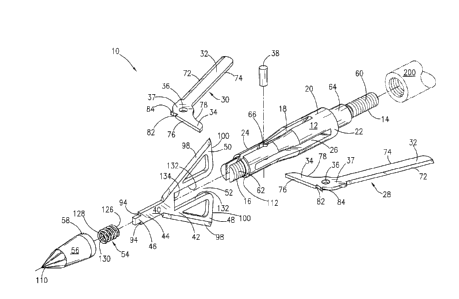
FIG. 1 is an exploded view of an embodiment of the broadhead.
FIG. 2 is a perspective view of an embodiment of the broadhead with the
pivoting blades
in their non-deployed position.
FIG. 3 is a top view of the embodiment of the broadhead shown in FIG. 2.
FIG. 4 is a front view of the embodiment of the broadhead shown in FIG. 2.
FIG. 5 is a side view of the embodiment of the broadhead shown in FIG. 2.
FIG. 6 is a cross-sectional view of the embodiment of the broadhead shown in
FIG. 5
taken along lines 6-6 thereof.
FIG. 7 is a cross-sectional view of the embodiment of the broadhead shown in
FIG. 4
taken along lines 7-7 thereof.
CA 2984662 2017-11-03
FIG. 8 is a perspective view of an embodiment of the broadhead with the
pivoting blades
in their deployed position.
FIG. 9 is a front view of the embodiment of the broadhead shown in FIG. 8.
FIG. 10 is a top view of the embodiment of the broadhead shown in FIG. 8.
FIG. 11 is a side view of the embodiment of the broadhead shown in FIG. 8.
FIG.12 is a cross-sectional view of the embodiment of the broadhead shown in
FIG. 10
taken along lines 12-12 thereof.
FIG. 13 is a cross-sectional view of the embodiment of the broadhead shown in
FIG. 11
taken along line 13-13 thereof.
DETAILED DESCRIPTION OF THE DISCLOSURE
With reference to the figures where like elements have been given like
numerical
designation to facilitate an understanding of the disclosure, and in
particular with reference to the
embodiment of broadhead 10 illustrated in FIG. 1, broadhead 10 may be
constructed of ferrule
12, first and second pivoting blades 28, 30, pivot pin 38, reciprocating blade
40, spring 54, and
tip 56. Ferrule 12 may include lower section 14 and upper section 16. Ferrule
12 may also
include intermediate section 64 and blade section 20. Intermediate section 64
interconnects
11
CA 2984662 2017-11-03
lower section 14 and blade section 20. Lower section 14 may be configured for
detachable
connection to the front end of arrow or bolt shaft 200. For example, lower
section 14 may
contain threads 60 that threadedly connect to mating threads (not shown) at
the front end of the
arrow or bolt shaft 200 or to an outsert/insert (not shown) positioned within
the front end of the
arrow or bolt shaft 200 as would be understood by one of ordinary skill in the
art.
With reference to FIG. 1, ferrule 12 may contain split 18 longitudinally
extending within
blade section 20. Split 18 may extend from upper section 16 entirely or
partially through blade
section 20. As seen in FIG. 1, split 18 extends substantially or partially
through blade section 20.
Split 18 divides blade section 20 into first side section 22 and second side
section 24. Each of
the first and second side sections 22, 24 may include a longitudinally
extending aperture 26. The
length of apertures 26 may be dimensioned so as to receive all or portion of
respective first or
second pivoting blades 28, 30 in their non-deployed position. The height of
apertures 26 may be
dimensioned to accommodate first and second pivoting blades 28, 30 in stacked
arrangement.
Again with reference to FIG. 1, first and second pivoting blades 28, 30 may
each include
blade arm 32 and deployment arm 34. Pin recess 36 may be positioned in
transition area 37
between blade arm 32 and deployment arm 34. First pivoting blade 28 may be
configured for
partial placement within aperture 26 of side section 22. Second pivoting blade
30 may be
configured for partial placement within aperture 26 of side section 24. Pin
recesses 36 of the
first and second pivoting blades 28, 30 may be aligned (e.g., with second
pivoting blade stacked
upon first pivoting blade 28) within ferrule 12. First and second pivoting
blades 28, 30 may be
pivotably connected together by placement of pivot pin 38 into enlarged recess
66 of ferrule 12
12
CA 2984662 2017-11-03
and through and within aligned pin recesses 36. In this configuration, each of
first and second
pivoting blades 28, 30 may be independently pivotable in relation to ferrule
12 and each other.
FIG. 1 also reveals that blade arms 32 may each contain cutting edge 72.
Cutting edges
72 may each contain a sharpened cutting surface that will, for example, create
a wound channel
within an animal when broadhead 10 makes impact with and enters the body of
the animal.
Cutting edges 72 may extend along a portion of blade arm 32 or the entirety of
blade arm 32.
Blade arms 32 may each also contain edge 74. Edge 74 may or may not be
configured as a
cutting surface. In one embodiment, edge 74 is configured as a dull or non-
cutting surface.
Also as seen in FIG. 1, each of deployment arms 34 may include (front) edge 76
that may
or may not be a cutting surface. Each of deployment arms 34 also may include
edge 78 that may
or may not be a cutting surface. In one embodiment, edges 76 and 78 are not a
cutting surface.
For example, edges 76 may each be configured with a dull or non-cutting
surface designed to
provide sufficient contact area when broadhead 10 (affixed to arrow or bolt
shaft 200), after
being fired, impacts an animal and begins to enter the body of the animal.
Contact of edges 76
with the animal upon impact of broadhead 10 will cause deployment of blade
arms 32. Each of
edges 76 also may contain first locking shoulder 82 and second locking
shoulder 84. First
locking shoulders 82 hold, lock or maintain respective first and second
pivoting blades 28, 30 in
their non-deployed positions. Second locking shoulders 84 hold, lock or
maintain respective first
and second pivoting blades 28, 30 in their deployed positions. In one
embodiment, only the
second locking shoulder is provided. The mechanisms for locking first and
second pivoting
blades 28, 30 in either their non-deployed or deployed positions will be
explained hereinbelow.
13
CA 2984662 2017-11-03
With further reference to FIG. 1, reciprocating blade 40 may include lower
blade section
42 and upper elongated neck section 44. Neck section 44 may include tab
portion 46. At the
base of tab portion 46, neck section 44 includes two support shoulders 94.
Lower blade section
42 may include first arm section 48 and second arm section 50 spaced apart by
slot 52. Slot 52
may be defined by opposing side edges 132 of respective first and second arm
sections 48, 50
interconnected by transverse edge 134. Reciprocating blade 40 may be
configured to be inserted
into split 18 with first and second arm sections 48, 50 positioned around
pivot pin 38 and
transition areas 37 of first and second pivoting blades 28, 30 where pivot pin
38 is inserted into
pin recesses 36 of blades 28, 30. Thus, first and second arm sections 48, 50
contain¨within slot
52¨pivot pin 38 positioned within aligned pin recesses 36 of first and second
pivoting blades
28, 30. When reciprocating blade 40 is in operational position within split 18
of ferrule 12, pivot
pin 38 and the pivoting point or axis of first and second pivoting blades 28,
30 are positioned
within slot 52 of reciprocating blade 40 and between first and second arm
sections 48, 50, which
contain first and second pivoting blades 28, 30 in operative pivoting position
within ferrule 12.
FIG. 1 also shows that spring 54 may include lower end 126 and upper end 128.
Spring
54 may also include internal cavity 130. When broadhead 10 is assembled, lower
end 126 of
spring 54 abuts supporting shoulders 94 of neck section 44. Upper end 128 of
spring 54 abuts
upper surface 124 (not shown) of tip 56. Internal cavity 130 of spring 54
receives tab portion 46
of reciprocating blade 40. Spring 54 may bias reciprocating blade 40. For
example, expansion of
spring 54 biases reciprocating blade 40 in a downward direction relative to
ferrule 12.
Conversely, movement of reciprocating blade 40 in an upward direction relative
to tip 56 causes
compression of spring 54.
14
CA 2984662 2017-11-03
FIG. 1 further depicts that tip 56 may include point 110. Point 110 may be
tapered and in
a chiseled pattern. Point 110 is configured for penetration of an animal. Tip
56 may also include
lower end 58 that detachably connects to upper section 16 of ferrule 12. For
example, tip 56 may
contain internal threads that mate with threads 62 on upper section 16 of
ferrule 12. Thus, tip 56
may be connected to ferrule 12 by threaded connection. When tip 56 is fully
threaded to threads
62 of upper section 16, lower end 58 abuts and is supported by shoulder 112 of
ferrule 12.
FIGS. 2-7 show broadhead 10 with first and second pivoting blades 28, 30 in
their non-
deployed position. The non-deployed position is used when firing arrow or bolt
shaft 200 to
which broadhead 10 is affixed. During firing and flight of broadhead 10, first
and second
pivoting blades 28, 30 maintain their non-deployed position due to the
application of a
downward biasing force produced by spring 54 that is transferred to
reciprocating blade 40 and
from reciprocating blade 40 to first and second pivoting blades 28, 30 as will
be explained
herein. In the non-deployed position, first and second pivoting blades 28, 30
are retracted. For
example, blade arms 32 of first and second pivoting blades 28, 30 may each be
entirely,
substantially, or partially contained within respective apertures 26 of blade
section 20. As a
further example, blade arms 32 may each be positioned substantially parallel
with and adjacent
to blade section 20 and deployment arms 34 may be substantially perpendicular
to blade section
20. Alternatively, the outer diameter of the profile of first and second
pivoting blades 28,30 in
the non-deployed position (e.g., the cutting diameter) may be equal to or less
than the cutting
diameter of reciprocating blade 40. For example, the cutting diameter of first
and second
pivoting blades 28, 30 may be less than 1 inch. Alternatively, blade arms 32
may each be set at
an angle in the range of 100 and 20 relative a longitudinal axis running
through ferrule 12 from
CA 2984662 2017-11-03
upper section 16 to lower section 14. Alternatively, blade arms 32 may each be
set at an angle of
about 15 relative a longitudinal axis running through ferrule 12 from upper
section 16 to lower
section 14.
FIGS. 3, 5 and 6 show the stacked arrangement of first and second pivoting
blades 28, 30.
First pivoting blade 28 is positioned beneath second pivoting blade 30.
Deployment arm 34 of
first pivoting blade 28 extends outwardly from second side section 24 of
ferrule 12 while blade
arm 32 extends outwardly from first side section 22. Similarly, deployment arm
34 of second
pivoting blade 30 extends outwardly from first side section 22 of ferrule 12
while blade arm 32
extends outwardly from second side section 24.
FIG. 4 reveals inner walls 70 of each of first and second side sections may
contain indent
68. Indents 68 may each be C-shaped so as to accommodate the placement of
pivot pin 38
therein. Indents 68 form enlarged recess 66 in slit 18 through which pivot pin
38 is inserted and
placed within aligned pivot recesses 36 of first and second pivoting blades
28, 30.
As seen in FIG. 6 and 7, tip 56 may further include inner cavity 114 defined
by inner
surface 116. Inner cavity 114 may include separate compartments. For example,
inner cavity 114
may include lower section compartment 118 and upper section compartment 122.
Lower section
compartment 118 may have an internal diameter greater than the internal
diameter of upper
section compartment 122. Upper section compartment 122, defined by inner
surface 116, may
be dimensioned to receive and accommodate the outer diameter of spring 54.
Surface 124 of
upper section compartment 122 supports upper end 128 of spring 54. Inner
surface 116 of lower
16
CA 2984662 2017-11-03
compartment 118 (or a portion thereof) may include threads 120 that mate with
corresponding
threads 62 on upper section 16 of ferrule 12 when tip 56 is threadedly
connected to ferrule 12.
FIGS. 5, 6, and 7 shows first and second pivoting blades 28, 30 held or locked
into their
non-deployed position wherein first and second pivoting blades 28, 30 are
situated substantially
within or in close proximity to respective apertures 26. This represents the
firing and flight
placements of first and second pivoting blades 28, 30. Surface 124 of upper
section compartment
122 acts as a stop for upper end 128 of spring 54. Spring 54 stores
compression/expansion force.
The force in spring 54 forces reciprocating blade 40 in a downward direction
relative to lower
section 14 of ferrule 12. Transverse edge 134 of reciprocating blade 40 pushes
down on edges 76
of first and second pivoting blades 28, 30 thereby locking, holding or
maintaining first and
second pivoting blades 28, 30 in their non-deployed position. Transverse edge
134 sets against
first locking shoulder 82 preventing further retraction of blade arms 32
towards blade section 20
of ferrule 12 thus establishing a set or predetermined non-deployed position
for first and second
pivoting blades 28, 30. First and second pivoting blades 28, 30 will maintain
this non-deployed
position during firing and flight of an arrow or bolt shaft 200 to which
broadhead 10 is affixed.
In this non-deployed firing and flight position, broadhead 10 provides a
streamlined design
optimal for firing from an archery bow or crossbow and optimal for sustaining
a straight and
extended flight pattern upon firing.
FIG. 7 shows that tab portion 46 is configured and dimensioned to receive and
accommodate spring 54. Tab portion 46 may include an outer diameter less than
the outer
diameter of neck section 44. The outer diameter of tab portion 46 is sized so
as to be insertable
17
CA 2984662 2017-11-03
into the interior cavity 130 of spring 54. Tab portion 46 terminates at
shoulders 94 of neck
section 44. Shoulders 94 support lower end 126 of spring 54 and act to
transfer force in spring 54
to reciprocating blade 40 in order to reciprocate reciprocating blade 40 in a
downward direction
relative to lower section 14 of ferrule 12. Each of first and second arm
sections 48, 50 of lower
blade section 42 may include first edge 98. Each of first edges 98 may contain
a sharpened
cutting surface that will create a wound channel within an animal when
broadhead 10 makes
impact with the animal. Each of first edges 98 may extend along a portion of
respective first and
second arm sections 48, 50 or may extend along the entirety of respective
first and second arm
sections 48, 50. Each of first and second section arms 48, 50 may include
bottom edge 100.
Each of bottom edges 100 is configured as a dull or non-cutting surface. In
one embodiment that
will be described herein, bottom edges 100 are configured to be manipulated by
a person using
the broadhead to apply force in an upward direction relative to tip 56 to
reciprocate reciprocating
blade 40.
With further reference to FIG. 7, lower blade section 42 may be dimensioned in
a
triangular shape with first edges 98 extending from distal point 102 to
proximal point 104 at an
angle in the range of 15 to 40 or at an angle of about 30 in relation to a
longitudinal axis
running through reciprocating blade 40. At its greatest outer diameter,
reciprocating blade 40 has
a cutting diameter of about 1 inch. First and second arm sections 48, 50 may
be solid or contain
apertures 106. Apertures 106 lessen the overall weight of reciprocating blade
40 by removing
material. Slot 52 is dimensioned to accommodate the width of first and second
pivoting blades
28, 30 in stacked arrangement and contain pivot pin 38 in place within the
aligned recesses 36 of
the first and second pivoting blades.
18
CA 2984662 2017-11-03
FIGS. 8-13 depict broadhead 10 in the deployed position after making impact
with an
animal or other object. Upon impact, first and second pivoting blades 28, 30
are actuated from
the non-deployed position shown in FIG. 2 to their deployed position shown in
FIG. 8. In the
deployed position, blade arms 32 have moved substantially out and away from
respective
apertures 26 and blade section 20 of ferrule 12. In their deployed position,
first and second
pivoting blades 28, 30 may be positioned at an angle in the range of between
40 to 80 in
relation to a longitudinal axis running through ferrule 12 and may be
positioned at an angle of
about 60 in relation to the longitudinal axis running through ferrule 12. In
the deployed
position, deployment arm 34 of first pivoting blade 28 will have moved from
its original
substantially perpendicular position relative to blade section 20 of ferrule
12 to an angled
position that aligns with the positional angle of blade arm 32 of second
pivoting blade 30
(deployment arm 34 being situated below and adjacent to blade arm 32 of second
pivoting blade
30). Likewise, deployment arm 34 of second pivoting blade 30 will have moved
from its original
substantially perpendicular position relative to blade section 20 of ferrule
12 to an angled
position that aligns with the positional angle of blade arm 32 of first
pivoting blade 28
(deployment arm 34 being situated below and adjacent to blade arm 32 of first
pivoting blade
28). In their deployed position, first and second pivoting blades 28, 30 may
have a cutting
diameter in the range of 1.5 inches to 3 inches, or a cutting diameter of
about 2 inches.
Reciprocating blade 40 may have a cutting diameter of 0.5 inches to 1.5 inches
or a cutting
diameter of about 1 inch.
FIGS. 12 and 13 show first and second pivoting blades 28, 30 held or locked
into their
deployed position wherein first and second pivoting blades 28, 30 are fully
extended outwardly
19
CA 2984662 2017-11-03
from respective first and second side sections 22, 24 of blade section 20 of
ferrule 12. To achieve
their deployed position, a sufficient force must be applied to first and
second pivoting blades 28,
30 to overcome the biasing force applied to them by transverse edge 134 of
reciprocating blade
40 vis-à-vis spring 54 so that edges 76 of deployment arms 34 are able to move
in a direction
causing first locking shoulder 82 to move away from transverse edge 134 and
causing second
locking shoulder 84 to move towards and past transverse edge 134. When second
locking
shoulders 84 moves past transverse edge 134, the biasing force caused by
spring 54 forces
reciprocating blade 40 in a downward direction relative to lower section 14 of
ferrule 12 such
that transverse edge 134 is forced against edges 76 and sets adjacent to
second locking shoulder
84. Second locking shoulders 84 hold or lock first and second pivoting blades
28, 30 in their
deployed position and prevent first and second pivoting blades 28, 30 from
retracting into their
non-deployed position.
Broadhead 10 is designed so that upon impact with an animal or other object,
the contact
force resulting from such impact is sufficient to cause first and second
pivoting blades 28, 32 to
deploy from their firing, flight, and non-deployed position shown in FIG. 2 to
their deployed
position as shown in FIG. 8. In other words, the contact force created by the
impact of
broadhead 10 with the animal will result in sufficient force being applied to
first and second
pivoting blades 28, 30 to overcome the biasing force being applied by
transverse edge 134 of
reciprocating blade 40 vis-à-vis spring 54 so that the outward rotation or
pivoting of first and
second pivoting blades 28, 30 due to the impact overcomes the biasing force of
transverse edge
134 placed upon edges 76. As edges 76 of deployment arms 34 contact the
animal, first and
second pivoting blades 28, 30 are pushed outwardly and into their deployed
position. The
CA 2984662 2017-11-03
outward rotation or pivoting of first and second pivoting blades 28, 30
results in transverse edge
134 being placed in position next to second locking shoulder 84, which
prevents first and second
pivoting blades 28, 30 from retracting to their non-deployed position.
Therefore, upon impact of broadhead 10 with an animal, first and second
pivoting blades
28, 30 are pivoted from their non-deployed position to their deployed position
resulting in a
second and larger cutting configuration. Due to the locking mechanism of the
second locking
shoulder 84 resting against transverse edge 134 of reciprocating blade 40,
first and second
pivoting blades 28, 30 are maintained in their deployed position while
broadhead 10 enters the
animal or object and thereby creates a maximum wound area or pattern within
the animal or
object. As stated previously, in one embodiment, the maximum diameter of the
first and second
pivoting blades in their deployed position is about 2 inches.
In order to reset first and second pivoting blades 28, 30 from their deployed
position to
their non-deployed position, a user may apply an upward force in the direction
of tip 56 to one or
both of bottom edges 100 of lower blade section 42 of reciprocating blade 40
thereby pushing
transverse edge 134 of reciprocating blade 40 upward and away from both first
and second
locking shoulders 82, 84 thereby releasing any contact of transverse edge 134
with first and
second pivoting blades 28, 30. First and second pivoting blades 28, 30 will
retract to their non-
deployed positions by gravitational force if broadhead 10 is held in an
upright position or a user
may push first and second pivoting blades 28, 30 back into the non-deployed
position.
21
CA 2984662 2017-11-03
Ferrule 12 may be composed of any durable material. For example, ferrule 12
may be
made of a metal, such as aluminum. Reciprocating blade 40 and first and second
pivoting blades
28, 30 may be made from any durable material. For example, reciprocating blade
40 and first and
second pivoting blades 28, 30 may be made of metal, such as stainless steel.
Tip 56 may likewise
be made of any durable material. For example, tip 56 may be made of metal and
chiseled.
While various embodiments of the disclosure have been described, it is to be
understood
that the embodiments described are illustrative only and that the scope of the
invention is to be
defined solely by the appended claims when accorded a full range of
equivalents, many
variations and modifications naturally occurring to those skilled in the art
from a perusal hereof.
22
CA 2984662 2017-11-03