Note: Descriptions are shown in the official language in which they were submitted.
WEB MATERIAL ADVANCEMENT ARRANGEMENT WITH AN ENTRY
DRIVE SYSTEM IN A PACKAGING MACHINE
[0001]
BACKGROUND
[0002] Web material advancement systems that feed web materials within product
processing machines, such as packaging machines, are known. Web material
advancement systems typically have exit drive systems that pull web material
toward exit
ends of the web material advancement systems to feed web processing stations
downstream in the packaging machines. Such exit drive systems typically have a
pair of
independent servo motors or other drive units on both of the left and right
sides of the
exit end of the web material advancement systems. The servo motors are
controlled to
provide synchronous operation of both motors to ensure the web material does
not skew
as it is pulled from a downstream position to advance in the upstream-to-
downstream
direction. However, these independent paired-drive exit drive systems are
complex and
can require corresponding complex control methodologies for synchronization
corrections in order to maintain coordinated driving of the left and right
sides of the web
material advancement systems. Other exit drive systems have incorporated a
single drive
shaft at the outlet end of the web advancement system that is positioned at a
low
elevation to provide package clearance. These separate-shaft exit drive
systems have
pairs of sprockets that are drive-coupled via chains to upper pairs of input
sprockets to
impart movement to a pair of gripper chains with web grippers. However, the
independent chains of the chain-driven exit drive systems need maintenance and
inspection and can stretch or otherwise wear at different rates, which can
lead to skewed
pulling of the web material toward the outlet end of the web advancement
systems.
1
CA 2984676 2019-11-11
SUMMARY OF THE INVENTION
[0003] According to one aspect of the invention, a web material advancement
arrangement is provided that has an entry drive system that is configured to
push a web
material from storage on a roll toward a web processing station of a packaging
machine.
[0004] According to another aspect of the invention, a web material
advancement
arrangement with an entry drive system is provided. The web material
advancement
arrangement can receive a web material from a storage roll and advance the web
material
through a machine, such as a packaging machine. The web material advancement
arrangement may include an entry end that receives the web material from
storage on the
roll and an exit end that delivers the web material from the web material
advancement
arrangement downstream toward the rest of the packaging machine. An entry
drive system
may be arranged at the entry end of the web material advancement arrangement
and is
configured to push the web material in a downstream direction from the entry
end toward
the exit end of the web material advancement arrangement.
[0005] According to another aspect of the invention, a pair of rotatable
drive members
is arranged at the entry end of the web advancement arrangement. The web
advancement
arrangement may define a pair of sides, and the pair of rotatable drive
members may be
arranged in rotational unison with each other at the respective sides. The
pair of rotatable
drive members may be defined by a pair of drive sprockets, and the entry drive
system may
drive the pair of drive sprockets as a unit. The pair of drive sprockets may
be mounted to a
drive roller at the entry end of the web material advancement arrangement. The
drive roller
may lock the pair of drive sprockets into rotational unison with each other.
[0006] According to another aspect of the invention, the drive roller
defines a drive
roller axis of rotation, and the motor includes a motor output shaft that
defines a motor
output shaft axis of rotation that is perpendicular to the drive roller axis
rotation. A pair of
spaced-apart rails 12 may extend between the entry end and exit end of the web
material
advancement arrangement to support the web material and wherein the motor is
arranged
generally parallel to the pair of spaced-apart rails.
2
CA 2984676 2017-11-03
[0007] According to another aspect of the invention, the input shaft may
define an input
shaft outer portion that receives power from the motor and an opposite input
shaft inner
portion. A first drive sprocket may be mounted to the input shaft inner
portion to lock the
first drive sprocket and the input shaft into rotational unison with each
other. The drive
roller may define first and second ends, with the first end mounted to the
input shaft inner
portion to lock the drive roller and the input shaft into rotational unison
with each other. A
support shaft may include a support shaft inner portion and a support shaft
outer portion.
The support shaft inner portion is mounted to the second end of the drive
roller to lock
support shaft and the drive roller in rotational unison with each other. A
second drive
sprocket is mounted to the support shaft inner portion to lock the second
drive sprocket and
the support shaft into rotational unison with each other. A power flow path
may be defined
that transfers torque (i) from the input shaft inner portion to the first
drive sprocket and the
first end of the drive roller, (ii) through the length of the drive roller,
(iii) from the second
end of the drive roller to the support shaft inner portion, and (iv) from the
support shaft
inner portion to the second drive sprocket.
[0008] According to another aspect of the invention, the entry drive system
may include
a motor, which may be the sole prime mover for the entry drive system, and a
gearbox that
receives power from the motor. The gearbox delivers power from the motor to
the pair of
sprockets and the roller to push the web material in a downstream direction
from the entry
end toward the exit end of the web material advancement arrangement. The
gearbox may
directly drive an input shaft that is mounted to the drive roller.
[0009] According to another aspect of the invention, a web material
advancement
arrangement is provided for advancing web material in a machine having an
upstream end
and a downstream end, such as a packaging machine, and which includes an entry
drive
system located at the upstream end of the machine. The web material
advancement
arrangement includes a web material engagement arrangement, which may be in
the form
of spaced-apart endless chains or belts equipped with web material gripper
mechanisms
that engage the web material adjacent opposite edges of the web material. The
entry drive
system includes a pair of rotatable drive members, such as pulleys or
sprockets which are
3
CA 2984676 2017-11-03
engaged with the web material engagement arrangement. A single motor includes
a
rotatable output member that is drivingly engaged with the rotatable drive
members.
Operation of the motor functions to impart rotation to the rotatable output
member, which
in turn causes simultaneous rotation of the rotatable drive members and
advancement of
the web material engagement arrangement and thereby advancement of the web
material.
BRIEF DESCRIPTION OF THE DRAWINGS
[00010] A clear conception of the advantages and features constituting the
present
invention will become more readily apparent by referring to the exemplary, and
therefore
non-limiting, embodiments illustrated in the drawings accompanying and forming
a part of
this specification, wherein like reference numerals designate the same
elements in the
several views.
[00011] In the drawings:
[00012] FIG. 1 is an isometric view of an upstream end portion of a machine,
such as a
packaging machine, incorporating a web material advancement arrangement with
an
entrance-end or entry drive system for advancing web material, according to an
embodiment of the invention;
[00013] FIG. 2 is a partial isometric view of a portion of the web material
advancement
arrangement of FIG. 1 from an opposite angle relative to the partial isometric
view
illustrated in FIG. 1;
[00014] FIG. 3 is an enlarged partial isometric view of a portion of the web
material
advancement arrangement of FIG. 1;
[00015] FIG. 4 is an isometric view of various components of the entry drive
system
according to an embodiment of the invention, separate from the rest of the web
material
advancement arrangement;
[00016] FIG. 5 is a top plan view of the components of the entry drive system
of FIG. 4;
[00017] FIG. 6 is an exploded isometric view of the components of the entry
drive system
of FIG. 4;
4
CA 2984676 2017-11-03
[00018] FIG. 7 is cross-sectional view of the various components of the entry
drive
system of FIG. 4; and
[00019] FIG 8 is another cross-sectional view of the various components of the
entry
drive system of FIG. 4, showing a schematic representation of a power flow
path through
the various components.
[00020] FIG. 9 is an isometric view of various components of a variant of the
entry drive
system of FIG. 4;
DETAILED DESCRIPTION OF THE DRAWINGS
[0021] The present invention and the various features and advantageous
details thereof
are explained more fully with reference to the non-limiting embodiments
described in
detail in the following description.
[0022] Referring generally to the drawings, a portion(s) of a machine that
utilizes web
material, and that incorporates an entrance-end or entry drive system for
advancing the web
material according to an embodiment of the invention, is illustrated in FIGS.
1-9.
Representatively, the machine may be a packaging machine in which web material
is
supplied from storage on a roll and advanced through the machine. During such
advancement, components of the machine act on the web material to first deform
the web
material to create a series of upwardly facing cavities, which are then filled
with product
to be packaged. After placement of product into the cavities, the machine
supplies a second,
top web that overlies the bottom web within which the cavities are formed.
Components of
the machine then seal the top and bottom webs together about the cavities so
as to seal
product within each cavity. The sealed webs are then separated longitudinally
and
transversely to form individual product packages. A representative type of
packaging
machine within which the entrance-end or entry drive system, according to an
embodiment
of the invention, may be a form-fill-seal packaging machine such as is
available from CP
Packaging LLC of Appleton, Wisconsin under its designation VisionPak. It is
understood,
however, that the entrance-end or entry drive system according to an
embodiment of the
invention may be used in any type of packaging machine that utilizes web
material within
CA 2984676 2017-11-03
which product cavities are formed during advancement of the material through
the
machine. It is further understood that the entrance-end or entry drive system,
according to
an embodiment of the invention, may be used in applications other than
packaging
machines in which a flexible web material is supplied from a roll and advanced
through
the machine for any purpose.
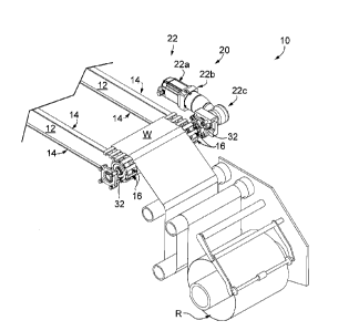
100231 As shown in FIGS. 1-3, a web material advancement arrangement for
moving
web material, shown at web W, through a machine is generally shown at 10. In a
manner
as is known, the web W may be supplied from storage on a roll R that is
rotatably supported
by the frame of the machine (not shown). In addition, the frame of the machine
supports a
pair of spaced-apart rails 12 of the web material advancement arrangement 10,
which in
turn supports a web material engagement arrangement. In a manner as is known,
the web
material engagement arrangement may be in the form of spaced-apart endless
chains or
belts, such as belts 14, that are equipped with web material gripper
mechanisms, such as
clip assemblies 16, that engage the web W adjacent opposite edges of the web
W.
Representatively, the web material engagement arrangement with belts 14 and
clip
assemblies 16 may be a clip belt-type web material engagement arrangement such
as is
shown and described in Buchko et al. US patent 7,934,362 titled Belt Driven
Clamping
Arrangement for Gripping and Advancing Web Material in a Packaging Machine. It
is
understood, however, that the web material engagement arrangement may have any
other
satisfactory configuration and construction as desired, and which is capable
of selectively
engaging web material adjacent its edges at an upstream end, advancing the web
material,
and then releasing engagement of the web material at a downstream end. In the
illustrated
embodiment, the clip assemblies 16 are arranged as a series of web-engaging
clip
assemblies 16 that are secured to each belt 14 along the length of the belt
14. The drawings
illustrate only a few of the clip assemblies 16 in the vicinity of the
upstream end of the
machine or entry end of the web material advancement arrangement, but it
is understood that the clip assemblies 16 are secured along the entire length
of
each belt 14. In
a manner as is known, each clip assembly 16 is
6
CA 2984676 2020-02-03
selectively opened at the upstream end of the machine and then closed onto the
web W so
that the web W is engaged by each clip assembly 16 adjacent the edge of the
web W.
[0024] As also shown in FIG. 1, the web material advancement arrangement 10
further
includes a drive system such as an entry drive system, shown generally at 20,
which is
located at the upstream or entrance end of the machine that defines an entry
end of the web
material advancement arrangement. The web material advancement arrangement 10
acts
on the web material engagement arrangement, namely belts 14 and clip
assemblies 16, for
imparting upstream-to-downstream motion to the upper runs of the belts 14 for
advancing
the web W through the machine.
[0025] The entry drive system 20 may define a direct drive system (FIGS. 1-
8) or an
indirect drive system (FIG. 9), explained in greater detail elsewhere herein.
Regardless of
whether the entry drive system 20 is configured as a direct or an indirect
drive system, it is
configured to push the web W (FIGS. 1-3) in a downstream direction from the
upstream or
entry end toward a downstream or exit end of the web material advancement
arrangement
10, from which the web W travels farther downstream in the machine for
processing.
[0026] Referring now to FIG. 1, generally, the drive system 20 includes a
drive
assembly 22 that is supported by the frame of the machine (not shown). Drive
assembly 22
is shown with a single electric motor 22a as a prime mover that can deliver
power for the
entry drive system 20. Motor 22a is shown here generally parallel to the frame
rail(s) 12
and delivers power to a gearbox 22b that may convert a rotational speed of a
motor output
shaft (not labeled) to an appropriate speed for operating downstream
components within
the power path of the entry drive system 20. Gearbox 22b is shown here with a
90-degree
gearbox section 22c that may include a worm gear set or bevel gear set to
change the
direction of power application from a motor output shaft 22d (FIG. 6). Gearbox
22b is
configured to directly deliver power from motor 22a to input shaft 30.
Although gearbox
22b is shown with a 90-degree gearbox section 22c, it is understood that power
transmission be achieved in other suitable ways, such as an inline gearbox or
by way of a
direct coupling to a motor.
7
CA 2984676 2017-11-03
[0027] Referring now to FIGS. 1-3, a pair of rotatable drive members, shown
here as
spaced-apart belt drive sprockets 32, is secured to the input shaft 30 and is
configured to
engage the belt 14 and clip assemblies 16 for moving the belt 14 and clip
assemblies 16 in
an upstream-to-downstream direction in response to operation of the drive
assembly 22. At
the exit end of web material advancement arrangement 10, a pair of spaced-
apart idler
sprockets may be connected to each other with an idler roller to support the
web W. Such
idler sprockets may have configurations and constructions similar to drive
sprockets 32
and may be supported by the frame of the machine at its downstream or exit end
in
generally the same manner as the drive sprockets 32 are supported at the
upstream or entry
end. In a manner as is known, the belts 14, with clip assemblies 16, are
carried about the
idler sprockets to provide the continuous loop forming the upper and lower
runs of the belts
14.
[0028] FIGS. 4-6 illustrate a direct drive system version of the drive
system 20 separate
from the machine and the web W. In the view provided in FIG. 4, it can be
appreciated that
each drive sprocket 32 includes a series of spaced recesses 34 about its outer
periphery,
each of which is configured to receive one of the clip assemblies 16. The belt
14 is engaged
by the areas of each sprocket 32 on either side of each recess 34. Referring
again to FIGS.
4-6, as can also be appreciated, the input shaft 30 is secured to a drive
roller shown as roller
36 that is located between the sprockets 32. Sprockets 32 are mounted to ends
of drive
roller 36, with drive roller 36 defining a common shaft that locks the drive
sprockets 32
into rotational unison with each other as driven by input shaft 30. The drive
roller 36 is
configured to support the web W between the edges of the web W that are
engaged by the
clip assemblies 16 at the upstream end of the machine or entry end of the web
material
advancement arrangement 10 and defines drive roller axis of rotation,
indicated by the
dashed line 38 (FIG. 1). The drive roller axis of rotation 38 is perpendicular
to a motor axis
of rotation, indicated by the dashed line 40 (FIG. 1).
[0029] Referring now to FIGS. 6-7, a squeeze collar 46 may provide a force
on a bore
of the gearbox and the input shaft 30 may define an input shaft inner portion
48 that is
shown here supported by bearing assembly 50, which may be a pillow block
bearing or
8
CA 2984676 2017-11-03
other suitable bearing. It is understood that the squeeze collar 46 and/or
torque transmitting
components that deliver power to drive sprocket 32 may have other
configurations, such
as a resilient or other coupling(s) to accommodate misalignment of, for
example, rotating
components in driving and driven relationship with each other. Regardless,
drive sprocket
32, which is closest to drive assembly 22, defines a first drive sprocket 32a
that is mounted
to the input shaft inner portion 48 to lock the first drive sprocket 32a and
the input shaft 30
into rotational unison with each other. The drive roller 36 defines first and
second ends 52,
54 with the first end 52 mounted to the input shaft inner portion 48 to lock
the drive roller
36 and the input shaft 30 into rotational unison with each other. A support
shaft 60 extends
from and supports the second end 54 of drive roller 36. Support shaft 60
includes support
shaft inner and outer portions 62, 64. The support shaft inner portion 62 is
mounted to the
drive roller's second end 54 to lock the support shaft 60 and the drive roller
36 in rotational
unison with each other. Drive sprocket 32, which is farthest from drive
assembly 22,
defines a second drive sprocket 32b that is mounted to the support shaft inner
portion 62
to lock the second drive sprocket 32b and support shaft 60 into rotational
unison with each
other. Support shaft outer portion 64 is supported by another bearing assembly
50.
[0030] Referring now to FIG. 8, a power flow path is schematically shown
through drive
system 20 components as represented with heavy-line arrows. The power flow
path
corresponds to torque transmission through the various components for pushing
web
material W (FIG. 1) in a downstream direction toward the exit end of web
material
advancement arrangement 10. Input shaft 30 receives torque or power at its
input shaft
inner portion 48 from motor 22a through gearbox 22b. The power is transmitted
through
input shaft 30 to its input shaft inner portion 48. At the input shaft inner
portion 48, power
is transmitted to the first drive sprocket 32a through a key 66 with a keyway
fit and to the
drive roller first end 52 through a flange 68 and fasteners 70 that secure the
flange 68
against a shoulder or land within a counterbore of the drive roller first end
52. Power is
transmitted through the drive roller 36 to its second end 54. At the drive
roller second end
54, power is transmitted through flange 68 of the support shaft inner portion
62 and
fasteners 70 that secure the flange 68 against a shoulder or land within a
counterbore of the
9
CA 2984676 2017-11-03
drive roller second end 54. At the support shaft inner portion 62, power is
transmitted to
the second drive sprocket 32b through a key 66 with a keyway fit. This results
in unit-like
simultaneous rotation of the first and second drive sprockets32a, 32b through
a single
power input of input shaft 30 from a single motor 22a to push the web material
W (FIG. 1)
in a downstream direction toward the exit end of web material advancement
arrangement
10.
[0031] FIG. 9 illustrate an indirect drive system version of the drive
system 20, showing
the drive system 20 separate from the machine and the web W. This indirect
drive system
20 of FIG. 9 is substantially similar to the direct drive system 20, shown in
a similar view
in FIG. 4, only differing in that the drive system 20 does not directly drive
input shaft 30,
but instead uses discrete spaced apart intervening components between gearbox
22b and
input shaft 30. As shown in FIG. 9, gearbox 22b delivers power to a drive
member, shown
as drive pulley 72, which is driven during operation of the drive assembly 22.
A driven
member, shown as driven pulley 74, is rotated by a flexible drive member such
as belt 76
that drivingly engages drive pulley 72 and driven pulley 74. Although in the
illustrated
embodiment the drive and driven members are in the form of drive and driven
pulleys 72,
74 and the flexible drive member is in the form of belt 76, it is understood
that any other
type of drive system, such as but not limited to a sprocket-and-chain system,
may be
employed.
[0032] In operation, the web W is advanced in an upstream-to-downstream
direction by
operation of the single motor drive assembly 22, which imparts rotation to the
input shaft
30 and thereby to the sprockets 32. In the direct drive system versions of
entry drive system
20, like that shown in FIG. 1, motor 22a and gearbox 22b directly rotate the
input shaft 30,
which rotates the drive sprocket 32 nearest the gearbox 22b, the drive roller
36, and the
drive sprocket 32 farthest from the gearbox 22b as a unit. In the indirect
drive system
versions of entry drive system 20, like that shown in FIG. 9, motor 22a and
gearbox 22b
rotate the drive pulley 72 which rotates the driven pulley 74 through belt 76.
Rotation of
pulley 74 rotates input shaft 30 and the drive sprocket 32 that is mounted to
an end of input
shaft 30 that is closest to the drive assembly 22, which also rotates the
drive roller 36 and
CA 2984676 2017-11-03
the drive sprocket 32 that is mounted farthest from the drive assembly 22. In
this way, in
both direct and indirect drive system versions of entry drive system 20,
activating the entry
drive system 20 pushes the web W in the upstream-to-downstream direction by
rotation of
the drive sprockets 32 at the entry end of web material advancement
arrangement 10 that
pushes and advances the belts 14 and clip assemblies 16 that carry the web W.
[0033] It should be understood that the above description, while indicating
representative embodiments of the present invention, is given by way of
illustration and
not of limitation. Many changes and modifications may be made within the scope
of the
present invention without departing from the spirit thereof, and the invention
includes all
such modifications.
[0034] Various additions, modifications, and rearrangements are
contemplated as being
within the scope of the following claims, which particularly point out and
distinctly claim
the subject matter regarding as the invention, and it is intended that the
following claims
cover all such additions, modifications, and rearrangements.
11
CA 2984676 2017-11-03