Note: Descriptions are shown in the official language in which they were submitted.
CA 02984758 2017-11-01
WO 2016/179158 PCT/US2016/030542
REAL SPACE 3D IMAGE GENERATION SYSTEM
CROSS REFERENCE TO RELATED APPLICATIONS
[0001] This application claims priority to and the benefit of U.S. Provisional
Patent
Application 62/156,564 filed May 4, 2015, the contents of which are
incorporated herein by
reference in their entirety.
RELATED FIELDS
[0002] Systems and methods for generating real space three dimensional images
(including
static and dynamic images), including laser systems and methods for producing
real space
three dimensional images using two (or more) photon absorption in gaseous
particles.
BACKGROUND
[0003] Currently known three dimensional imaging devices often rely upon
optical
illusions in an effort to trick the eyes and brain so that the human observer
experiences the
perception of viewing a three dimensional image. For example, certain passive
three
dimensional projection techniques involve the use of a projector to project
two orthogonally
polarized images, and the images sent with each polarization are such that
their separation
gives the appearance of depth. In another example, certain active three
dimensional
projectors can operate to project back-to-back images, one for the left eye
and one for the
right eye. Specially made glasses then rapidly turn on and off the left and
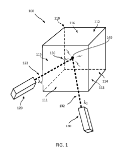
right lenses over
those eyes, respectively.
[0004] Although these and other three dimensional display techniques provide
many
benefits, still further improvements would be desirable for producing real
space three
1 / 58
CA 02984758 2017-11-01
WO 2016/179158 PCT/US2016/030542
dimensional images. Embodiments of the present invention provide solutions to
at least some
of these outstanding needs.
BRIEF SUMMARY
[0005] This patent application describes several examples of systems and
methods for
displaying in three dimensions static or dynamic images using laser beam
excitation of
gaseous particles. These systems and methods may utilize a three dimensional
illumination
volume that includes gaseous particles that emit visible light following the
absorption of
excitation laser energy. These systems and methods may include at least a
first laser
generating a first laser beam and a second laser generating a second laser
beam, and scanners
for directing the first and second laser beams to intersect in the
illumination volume and
excite gaseous particles at the beam intersection to a two-photon excited
state, such that
visible light is emitted by the particles at the beam intersection. The
scanners can further
operate to change the positions and/or orientations of the laser beams through
the
illumination volume so as to change a location of the laser beam intersection
in three
dimensions.
[0006] Light or electromagnetic radiation emitted from the excited gaseous
particles at the
beam intersections can be arranged and sequenced to generate static or dynamic
images. In
some cases, the gaseous particles are distributed in a transparent or semi-
transparent medium.
In some cases, one or more different types of particles can be used to emit
light in various
colors (e.g. red, green, yellow, blue). Software, hardware, and/or firmware
can be used to
control laser output and scanning so that light emits from addressable
locations of the
illumination volume, in a way that forms a static or dynamic three dimensional
image that is
perceptible to the eye of the viewer.
2 / 58
CA 02984758 2017-11-01
WO 2016/179158 PCT/US2016/030542
[0007] In one example, a system for displaying one or more images in three
dimensions
includes: a three dimensional illumination volume comprising a gas, the gas
including at least
a Rubidium vapor configured to emit a first type of visible light when at a
multi-photon
excited state; a first laser configured to generate a first laser beam at a
first wavelength that is
greater than 700 nm or less than 400 nm; a second laser configured to generate
a second laser
beam at a second wavelength that is greater than 700 nm or less than 400 nm,
the second
wavelength being different from the first wavelength; and the system
configured to direct the
first and second laser beams into the illumination volume such that the first
and second laser
beams intersect in the illumination volume to excite at least some Rubidium
particles at the
beam intersection to the multi-photon excited state such that the first type
of visible light is
emitted at the beam intersection.
[0008] The system may be configured to excite at least some of the Rubidium
particles at
the beam intersection to a 5D energy level.
[0009] The first type of visible light may include a light emission having a
wavelength
between 400 nm and 430 nm.
[0010] The 5D energy level may be a 5D512 energy level.
[0011] The system may further include a third laser configured to generate a
third laser
beam at a third wavelength that is different from the first wavelength and the
second
wavelength, the system configured to direct the first, second and third laser
beams into the
illumination volume such that the first, second and third laser beams
intersect in the
illumination volume to excite at least some of the Rubidium particles at the
beam intersection
to the multi-photon excited state such that the first type of visible light is
emitted at the beam
intersection.
[0012] In another example, a system for displaying one or more images in three
dimensions
includes: a three dimensional illumination volume including a first atomic or
molecular gas
3 / 58
CA 02984758 2017-11-01
WO 2016/179158 PCT/US2016/030542
configured to emit a first type of visible light when at a multi-photon
excited state, the
illumination volume further comprising a second buffer gas; a first laser
configured to
generate a first laser beam at a first wavelength; a second laser configured
to generate a
second laser beam at a second wavelength, the second wavelength being
different from the
first wavelength; and the system configured to direct the first and second
laser beams into the
illumination volume such that the first and second laser beams intersect in
the illumination
volume to excite at least some particles of the first gas at the beam
intersection to the multi-
photon excited state such that the first type of visible light is emitted at
the beam intersection.
[0013] The first gas may include an alkali gas and the second gas may include
a noble or
inert gas.
[0014] The alkali gas may include an atomic Rubidium vapor and the noble gas
may
include an Argon or Neon gas.
[0015] The second gas may include particles of a noble gas at a ground state
and the first
gas may include particles of the noble gas at a metastable state.
[0016] The first gas may include particles of the noble gas at a state in a
manifold of
metastable states.
[0017] The system may produce the particles of the noble gas at the metastable
state
outside of the illumination volume.
[0018] During operation of the system, a power of the first laser may be less
than 50 mW
and a power of the second laser may be less or more than 50 mW.
[0019] A temperature of the illumination volume during operation of the system
may be
below 120 C.
4 / 58
CA 02984758 2017-11-01
WO 2016/179158 PCT/US2016/030542
[0020] The system may be configured to generate in the illumination volume a
second type
and a third type of visible light, each of the second and third types of
visible light having
different wavelengths from the first type of visible light.
[0021] The system may further include a third laser configured to generate a
third laser
beam at a third wavelength that is different from the first wavelength and the
second
wavelength, the system configured to direct the first, second and third laser
beams into the
illumination volume such that the first, second and third laser beams
intersect in the
illumination volume to excite at least some of the particles of the first
atomic or molecular
gas to the multi-photon excited state such that the first type of visible
light is emitted at the
beam intersection.
[0022] The first type of visible light may be emitted at an intermediate
transition as the first
atomic or molecular gas decays from the multi-photon excited state.
[0023] The first atomic or molecular gas may include at least Rubidium
particles, the
system may be configured to excite at least some of the Rubidium particles at
the beam
intersection to at least one of a 5D312 energy level, 6D312 energy level,
7D312 energy level,
8D312 energy level, 9D312 energy level, 10D312 energy level, or 11D312 energy
level.
[0024] The first atomic or molecular gas may include at least Rubidium
particles, the
system may be configured to excite at least some of the Rubidium particles at
the beam
intersection to at least one of a 9D512 energy level, 101)512 energy level, or
11D512 energy level.
[0025] The first atomic or molecular gas may include at least Rubidium
particles, the
system may be configured to excite at least some of the Rubidium particles at
the beam
intersection to a 1181/2 energy level.
[0026] In another example, a system for displaying one or more images in three
dimensions
includes: a three dimensional illumination volume including a first gas
configured to emit a
/ 58
CA 02984758 2017-11-01
WO 2016/179158 PCT/US2016/030542
first type of visible light when at a first multi-photon excited state, a
second type of visible
light when at a second multi-photon excited state, and a third type of visible
light when at a
third multi-photon excited state, the illumination volume further comprising
an inert buffer
gas; a plurality of lasers configured to generate a plurality of laser beams,
wherein at least
some of the laser beams comprise different wavelengths; and the system
configured to direct
the laser beams into the illumination volume such that at least some of the
laser beams
intersect at a first beam intersection in the illumination volume to excite at
least some
particles of the gas at the first beam intersection to the first multi-photon
excited state such
that the first type of visible light is emitted at the first beam
intersection, such that at least
some of the laser beams intersect in the illumination volume at a second beam
intersection to
excite at least some of the particles of the gas at the second beam
intersection to the second
multi-photon excited state such that the second type of visible light is
emitted at the second
beam intersection, and such that at least some of the laser beams intersect in
the illumination
volume at a third beam intersection to excite at least some of the particles
of the gas at the
third beam intersection to the third multi-photon excited state such that the
third type of
visible light is emitted at the third beam intersection.
[0027] The first gas may be a mixture of gases.
[0028] The mixture of gases may be a mixture of at least three noble gases,
wherein each of
the three noble gases corresponds to emission of one of the types of visible
light.
BRIEF DESCRIPTION OF THE DRAWINGS
[0029] FIGS. 1 through 1(g) schematically illustrate non-limiting examples of
a three-
dimensional imaging system.
6 / 58
CA 02984758 2017-11-01
WO 2016/179158 PCT/US2016/030542
[0030] FIGS. 2 and 2(a) illustrate non-limiting examples of absorption and
emission
processes for a three-dimensional imaging system.
[0031] FIGS. 3 through 5 schematically illustrate additional non-limiting
examples of
three-dimensional imaging systems.
[0032] FIG. 6 illustrates a non-limiting example of a three-dimensional
imaging method.
DETAILED DESCRIPTION OF THE DRAWINGS
[0033] FIG. 1 depicts an example of a three-dimensional imaging system. As
shown, the
system 100 includes a three dimensional illumination volume 110 having at
least one atomic
or molecular gas. The atomic or molecular gas can include at least one type of
atoms or
molecules configured to emit a first type of visible light when at a two-
photon excited state.
In some cases, the system 100 can include a first laser 120 configured to
generate a first laser
beam 122 at a first wavelength ki and a second laser 130 configured to
generate a second
laser beam 132 at a second wavelength k2. The second wavelength k2 can be
different from
the first wavelength
[0034] The human eye has strong spectral sensitivity to light having
wavelength values
within a range from about 400 nm to about 700 nm. By using two-photon
absorption, lasers
producing light that is outside the spectral sensitivity of the eye, for
example at a wavelength
less than about 400 nm or greater than about 700 nm, can excite very small
regions of the gas
and make the gas emit light at visible wavelengths. Accordingly, the emission
from the gas
can be observed while the lasers exciting the gas are invisible to the human
eye. In other
instances, lasers producing light that is within the spectral sensitivity of
the eye may be
utilized.
[0035] System 100 can be configured to direct the first and second laser beams
122, 132 to
intersect in the illumination volume 110 to excite at least some of the first
type of atoms or
7 / 58
CA 02984758 2017-11-01
WO 2016/179158 PCT/US2016/030542
molecules at beam intersection 140 to the two-photon excited state, such that
a first type of
visible light 150 (e.g. a third wavelength X3) is emitted at the localized
region or beam
intersection 140. By changing (e.g. scanning) the location of laser beam
intersection 140, 3-
dimensional images can be produced in real space and, in some embodiments,
changed in
time to generate 3-dimensional videos.
Atomic or Molecular Gas
[0036] The illumination volume 110 has gaseous particles dispersed throughout
it. In some
cases, the particles may be present as a vapor, and may be atoms, molecules
(elemental or
compound), ions of atoms or molecules, or any combination thereof. In at least
some
embodiments, the gaseous particles have sufficient kinetic energy to move
freely throughout
the volume 110. When present within a container, gaseous particles can
distribute so that the
gas fills the volume of the container. In some cases, the gas within the
illumination volume
110 is transparent when not undergoing an absorption/emission process. In some
cases,
gaseous particles of the illumination volume 110 can be specifically chosen
based on their
selective absorption of one or more laser wavelengths and emission of one or
more visible
wavelengths.
[0037] Figure 2 depicts an example of a particle excitation and emission
process that may
occur at the laser beam intersection 140 shown in Figure 1. As shown in this
energy level
diagram, a first photon 210 at a first wavelength Xi or frequency in
combination with a
second photon 220 at a second wavelength k2 or frequency can operate to excite
a gaseous
particle from a lower state (e.g. a first state or ground state) to a higher
state (e.g. a second
state or excited state). For example, the two photons can excite an electron
of the particle
into a higher state (e.g. transitioning from one discrete energy level to
another), as the
electron absorbs incident energy from the light photons. Following absorption
of the two
photons and elevation to the higher energy state, the excited electron decays
to the lower state
8 / 58
CA 02984758 2017-11-01
WO 2016/179158 PCT/US2016/030542
while also emitting a photon 230. The emitted light may be at a wavelength X.3
within the
visible spectrum. Although Figure 2 depicts the lower to higher state
transition occurring in a
single step, in at least some embodiments, the transition will occur in
multiple steps, such as
by the first photon 210 causing a transition to an intermediate level and the
second photon
220 causing a transition from the intermediate level to the higher level.
Although Figure 2
depicts the higher to lower state transition occurring in a single step, in at
least some
embodiments, the transition will occur in multiple steps.
[0038] In some embodiments, the gas may include an atomic Rubidium (Rb) vapor.
Figure
2(a) depicts one example of a particle excitation and emission process for
atomic Rubidium.
In Figure 2(a), a first laser beam at 780 nm excites a 5S112 to 5P312
transition, where it will
remain for some period of time, and a second laser beam at 776 nm achieves the
two-photon
transition from the 5P312 to the 5D512 states. As shown in Figure 2(a), when
in this two-photon
excited state, one spontaneous emission decay pathway emits a blue photon at
420 nm (in this
particular case, infrared light is also emitted with the 420 nm light).
[0039] While not specifically shown in the figure, in this particular
embodiment, the
spontaneous emission pathway leading to the emission of 420 nm light proceeds
from the
5D512 state to the 6P312 state emitting an infrared photon. From the 6P312
level the light is able
to spontaneously emit a blue photon when it decays to the 5S112 level. There
are other decay
pathways emitting other light, however, in at least some embodiments, none of
those other
pathways emit light in the visible range of wavelengths.
[0040] In some embodiments, methods may be employed to encourage one
particular decay
pathway (e.g. the emission of light at a desired wavelength) over other
possible decay
pathways. For example, additional lasers may be introduced to allow for the
use of four-
wave mixing to promote decay down the desired decay pathway. In some
instances,
however, four-wave mixing will not be suitable for a particular embodiment
because
9 / 58
CA 02984758 2017-11-01
WO 2016/179158 PCT/US2016/030542
typically, the phase-matching conditions restrict the angular emission pattern
of the emitted
light to a very small solid-angle and in a precise and/or restricted angular
direction.
[0041] In some, although not all, embodiments, the emission pathway depicted
in Figure
2(a) may be particularly desirable because the dipole matrix elements for
these transitions is
larger than some other transition pathways for Rb. Larger dipole matrix
elements typically
means, in at least some instances, that the transition is easier to pump or
excite and often
means that the particular decay pathway will occur with higher probability
than other decay
pathways. Larger dipole matrix elements also typically mean shorter excited
state lifetimes.
Since the number of times an atom can be excited and decay within the dwell
time of the
scanning lasers is directly related to the intensity of the emitted light,
shorter excited state
lifetimes can be very beneficial.
[0042] In some, although not all, embodiments, the emission pathways employed
by the
present system may be beneficial over other decay pathways that include decay
through the
6P levels. In at least some instances, decay through the 6P level will mean
that in addition to
generating light at the desired wavelengths, such an approach will also
generate light at 420
and 421 nm. Such approaches, in many instances, are unable to generate pure
frequencies or
wavelengths in the visible range, which may reduce the area of the color gamut
which is
accessible for a full color display, either RGB, CMYK, or other color mixing
methodology.
[0043] The example of the excitation and emission process shown in Figure 2a
uses two
laser beams of infra-red light (e.g. having a wavelength of approximately 760
nm to 1000
p.m). More particularly, in this example, the two laser beams are both in the
near infrared
spectrum (e.g. having a wavelength of approximately 760 nm to 1500 nm). In
other
embodiments, other wavelengths outside of the spectrum of light visible to
humans (e.g.
outside of approximately 400 nm to 700 nm) may be employed. For example, in
some
embodiments, ultraviolet wavelengths may be employed.
/ 58
CA 02984758 2017-11-01
WO 2016/179158 PCT/US2016/030542
[0044] Additional / other pathways than that shown in Figure 2a may be
employed in some
embodiments. Some non-limiting examples include pathways ending on the 6D512,
7D512,
8D512, 12D512 levels, which utilize the 5P3/2 intermediate level. Other
examples include
pathways ending on the 8S112, 9S112, and 10S112 levels, which utilize the 5P12
and 5P3i2 levels.
Still other examples include excitation pathways to the (5-12)D3/2 levels, the
(9-11)D5/2
levels, and the 11S 1/2 level, which utilize either the 5P1/2 or 5P3i2
intermediate levels, all of
which generate visible light when they decay. Some of these pathways may be
preferable to
other pathways in certain embodiments. For example, excitation pathways to the
(9-11)D5/2
levels may have a larger cross-section and branching ratio to the 5P3i2 level
than the 12D5/2
level has to the 5P3i2 level. Broadly speaking, the 131/2 levels couple nearly
as strong to the
D3/2 levels as the P3/2 levels couple to the D5/2 levels (as measured by the
transition matrix
elements). Thus, the (5-12)D3/2 levels may be used with nearly the same
effectiveness as the
D5/2 levels in some embodiments. Additionally, the P3/2 levels appear to
couple to S1/2 levels
more strongly than at least some of the 131/2 levels (e.g. 8-10S112 to 5P1/2).
Levels above the
11S and 12D levels may also be used, however both the cross-section and
branching ratio to
the 5P levels appear to decrease for higher levels. Since, in at least some
embodiments, the
design of a suitable display system will depend upon the availability of
suitably configured
lasers at the various transition wavelengths, identification of all levels
which may be used
may be an important consideration in constructing a suitable system in at
least some
instances. US 4,881,068 to Eric J. Korevaar and Brett Spivey identify other
pathways that
may be utilized in some embodiments.
[0045] In some, although not necessarily all, instances, one issue with
excitation and decay
pathways that are based on two-transition processes is that it may be
difficult to find a
scenario where the laser addressing the upper transition can be infrared but
the decay
pathway creating the desired visible light does not occur on the final decay
to the ground
11 / 58
CA 02984758 2017-11-01
WO 2016/179158 PCT/US2016/030542
state. In the scenario where the visible light is generated on the final
transition to the ground
state, one potential issue in some instances is a trade-off between having a
sufficiently high
atomic or molecular number density so that sufficient visible light is
generated, but having a
sufficiently low density so that the generated light is able to propagate out
of the cell without
being substantially rescattered. In some embodiments, this trade-off limits
the density of the
Rb atoms in a practical embodiment. In some embodiments, one solution to this
problem is
using a buffer gas, which is discussed in greater detail below. On the other
hand, in scenarios
where the laser addressing the upper transition is at a visible wavelength
then the desired
fluorescence may occur on the upper transition. Consequently the light is not
resonant with
the many ground state atoms in the gas and may propagate freely out of the
volume.
However, a visible laser which is very powerful (as is required to generate
lots of
fluorescence) can also create a lot of laser scatter that is hard to filter
and eliminate. The laser
scatter cannot necessarily be filtered easily because it is at nearly the same
wavelength as the
generated fluorescence. Any attempt to filter laser scatter will also filter
the light emanating
from the illumination voxel.
[0046] In some embodiments, this issue may be addressed by making use of an
excitation
pathway involving three infrared lasers and using a cascade processes to
generate the visible
light so that the visible light is created in an intermediate transition in
the cascade process.
One non-limiting example of this approach which can be used to generate red
fluorescence is
the excitation pathway: 58112 -> 5P312 -> 413512 -> 8P312 with lasers at 780,
1530, and 953 nm.
Decay pathways giving rise to significant amounts visible light in an
intermediate transition
are as follows: 630 nm light is created via 8P312 -> 6D512 -> 5P312 -> 5S112
and 8P312 -> 6D312
5P312 -> 5 S 112, 620 nm light is created via 8P312 -> 6P312 -> 5P112 ->
5S112, 616 nm is created via
8P312 -> 8S112 -> 5P312 -> 5S112, and 607 nm light is created via 8P312 ->
8S112 -> 5P112 -> 5S112.
As with all other high-lying cascade processes, 420 and 421 nm light is still
created from
12 / 58
CA 02984758 2017-11-01
WO 2016/179158 PCT/US2016/030542
decay pathways that proceed though the 6P levels. Additionally, decay
processes through the
7S112 level will emit some radiation at 728 and 741 nm and decay from the 8P
and 7P levels
to the 5S level will generate ultraviolet radiation at 335 and 359 nm. The sum
of the
branching ratios through the five main visible decay pathways around 600 nm is
about 25%,
whereas the decay pathways giving rise to 420 and 421 nm light have a
branching ratio sum
of approximately 2%. With a two-laser process up to the 6D512 level, the
branching ratio to
the 5P312 level which generated 630 nm light is 78% with nearly the same
branching ratio sum
generating 420 and 421 nm light as before. Thus a three-laser excitation
process reduces the
efficiency of the decay process branching ratios by only a factor of three,
but completely
eliminates visible laser scatter.
[0047] In some embodiments, this approach is used to generate other colors of
visible
fluorescent light. For example, the excitation pathway 5S112 -> 5P312 -> 4D512
-> 9P3i2 makes
use of a 780, 1530, and 861 nm lasers. This transition will generate light
decaying to the 9S,
8S, 7D, and 6D levels. In Rubidium, decay to the s-levels tends to favor the
highest s-level,
and decay to the d-levels tends to be equally distributed. Consequently, the
emitted light will
have frequency components at 557, 565, 572, 607, 616, 620, and 630 nm, with a
heavier
relative weighting of the green-yellow frequencies (557, 565, and 572 nm). The
perceived
color is likely to be orange or yellow-orange. Some embodiments using this
approach can
also be used to generate predominantly green light by excitation up to the
10P, 11P, or 12P
levels from the 4D512 level using lasers at 813, 784, and 764 nm,
respectively. This approach
can also be used to generate visible fluorescence without using visible lasers
in different
atomic species.
[0048] We note that if continuous wave lasers are used in a saturation
condition, the total
population in the 8P312 level will likely be reduced relative to the
population which could be
excited to the 6D512 level in a two laser configuration. If pulsed lasers are
used, in principle,
13 / 58
CA 02984758 2017-11-01
WO 2016/179158 PCT/US2016/030542
the entire population in the localized region could be excited to the desired
level, either 8P312
in the three laser process, or the 6D512 in the two laser process. This can be
done using so
called '\pi pulses' to sequentially excite the atoms up to the desired excited
state. A \pi pulse is
a short laser pulse with a specific total area used to fully invert an atomic
transition. By
applying \pi pulses in sequence the population can be moved sequentially to
the desired
excited state before population decays significantly from any of the
intermediate levels. In
some instances, this approach requires precision in the total energy to
constitute a \pi pulse.
Additionally, in some instances, level degeneracies associated with hyperfine
or Zeeman
splitting tend to corrupt the process, and doppler broadening can also reduce
the efficiency of
the excitation process.
[0049] Another alternate approach in some embodiments for efficiently exciting
the atoms
to the desired level is to use amplitude-modulated stimulated Raman adiabatic
passage (AM-
STIRAP). In this approach resonant pulses are used in sequence to coherently
transfer the
atoms between two final states without populating the intermediate state. This
approach can
be used for both ladder systems and lambda-type systems and can be applied to
multi-level
systems with more than three levels. The pulse lengths for this process should
be much
shorter than the decoherence time of the pairs of levels. In a ladder system
the decoherence
time between pairs of levels is exceedingly short, nevertheless it may be
feasible if short laser
pulses, including femtosecond, picosecond, or possibly, in some cases, few
nanosecond
pulses, are used. This approach tends to be robust to level degeneracies
[Shore et al. Phys.
Rev. A 45, 5297 (1992)].
[0050] Still other non-limiting examples of possible excitation pathways
include excitation
up to the 5F712 level: 5S112 -> 5P312 -> 4D512 -> 5F712. Atoms excited up to
the 5F712 level will
decay through the 4, 5, and 6D512 levels and subsequently through the 5, 6,
and 7P312 levels,
respectively, generating visible light at 630 nm and 420 and 421 nm. In this
approach, only
14 / 58
CA 02984758 2017-11-01
WO 2016/179158 PCT/US2016/030542
about 2% of the atoms will decay to the 6D512 level to emit 630 nm light but
greater than 1%
will decay through the 6P312 level to emit 420 nm light.
[0051] The approaches described above for generating localized visible
fluorescence using
two or more lasers can also be generalized to noble gases. Most noble gases
can be excited
with electronic excitation to the so-called metastable states. Metastable
states have the
property that they are long-lived states with decay lifetimes far exceeding
other levels in the
same atom. The metastable states exhibit increased lifetimes because decay to
the common
ground state is forbidden by standard transition selection rules. Metastable
states can function
like effective ground states for higher-lying levels above them. For example,
in Argon, there
are two metastable states, the 3s23p5( 2%2)4s configuration 2 [3/ 2] o term
J=2 state and
the 3s23p5( 27,10/2
r )4s configuration 2[1/4 term J=0 state, using notation
consistent with
the NIST Atomic Spectra Database [Kramida, A., Ralchenko, Yu., Reader, J. and
NIST ASD
Team (2014). NIST Atomic Spectra Database (version 5.2), [Online], Available:
http://physics.nist.gov/asd [Tuesday, 17-Feb-2015]. National Institute of
Standards and
Technology, Gaithersberg, MD.] From the 3s23p5( 2%2)4s configuration 2[3/2]
term
J=2 state a laser at 811.53 nm can excite the atom to the 3s23p5( 2%2)4p
configuration
2[5/2] term J=3 state. Then a visible laser of wavelength of 603 nm can excite
the atom to
the 3s23p5( 2%2)5d configuration 2[7/2] term J=4 state. It is important to
note that
metastable states can be excited to states that are able to eventually decay
in some instances
to the Argon ground state via the emission of ultraviolet radiation, which may
be undesirable
in some, although not necessarily all, embodiments. Using levels that can
decay to the ground
state is not-preferred in some embodiments because energy is lost but visible
light is not
created. All of the levels listed above are forbidden from decaying to states
which decay to
the ground state. As such they constitute what we will call a metastable
manifold of states. By
this we mean that allowed decay pathways from these states always terminate on
the lowest
15 / 58
CA 02984758 2017-11-01
WO 2016/179158 PCT/US2016/030542
energy metastable state, in this case the 3s23/35( 2%2)4s configuration 2[3/2]
term J=2
state. Other excitation pathways may also be envisioned in Argon. For example,
instead of
using the excited state with the 3s23p5( 2%2)5d configuration, excitation to
the
3s23/35( 2%2)6d configuration 2[7/2]o term J=4 state is able to generate green
light at 550
nm. Similarly, excitation to the (7-12)D levels (same term and total electron
angular
momentum as the 4D and 6D states) emits (522, 506, 496, 489, 483, 480) nm
light,
respectively. This means that using the 5D, 7D, and 12D levels would allow for
a full RGB
color display in a single noble gas based system. As above, these states are
part of the
metastable manifold of states. We note that a small amount of ultraviolet
light will almost
always be generated in these systems from the cascade decay of the excited D
state to the 6-
12P levels and subsequently to the 4S metastable state. This type of decay can
be filtered by
using coatings on the display window in addition to being naturally filtered
by the display
windows themselves.
[0052] The similarity of all noble gases, including Neon, Argon, Krypton,
Xenon, and
Radon, means that if a sequence of levels can be found in one element, there
is a nearly
equivalent level structure in the other elements, albeit with different
transition frequencies
and different dipole transition matrix elements. This means, for example, that
mixtures of
noble gases can be used to generate multiple fully independent colors. In some
cases it may
be desirable to scan the red green and blue colored voxels independently. For
this to be
possible, in at least some embodiments, the laser driving the lower transition
has to be
different for each color. In some cases this may be possible with a single
atomic species by
utilizing different metastable states and intermediate transitions. In other
cases it may be
advantageous to mix atomic species so that each species creates one or more
colors. For
example, consider a set of levels in Krypton, with metastable state 4s24/35(
2%2)5s
configuration 2[3/2] term J=2, intermediate state 4s24/35( 2%2)5p
configuration
16 / 58
CA 02984758 2017-11-01
WO 2016/179158 PCT/US2016/030542
2[5/2] term J=3, and excited state 4s24p5( 2/1/2)6d configuration 2[7/2] term
J=4
state. The lower transition is accessed with 811.29 nm light, while the upper
transition is
accessed with and subsequently emits 646 nm light. The (7-12)D levels can be
accessed with
and emit (583, 552, 534, 522, 515, and 509) nm light, respectively.
[0053] Other levels in noble gases besides those mentioned above may be
utilized in some
embodiments. In some cases, additional decay pathways may be acceptable if the
branching
ratio through the primary pathway is large enough. Similar to the alkali
vapors, excitation to
the high-lying S levels can also be considered in noble gases. Additionally,
two- or three-
laser excitation with cascade emission of visible light can be considered in
the noble gases
similar to what is discussed above for alkali vapors.
[0054] In some embodiments utilizing noble gases, it may be challenging to
create a very
high density of metastable states without also creating large amounts of
visible fluorescence
from higher lying levels. In some embodiments, this problem can be surmounted
by
separating the metastable state creation region from the display volume with
an opaque tube
of sufficient length. Since higher-lying states decay very quickly, and the
metastable states
decay very slowly, atoms in higher lying states will decay before leaving the
tube while the
metastable states will not. In this way only ground state atoms and metastable
state atoms will
reach the display volume. One feature of using metastable atoms in at least
some instances is
that any atom in the ground state will act as a buffer gas to the metastable
states. More details
about buffer gases for some embodiments will be included below.
[0055] In some embodiments, metastable state densities close to those used in
Alkali
systems are possible. Typical methods for producing metastable states of noble
gases have an
efficiency in the range of 10A-5-10A-4. For Argon at a pressure of 10 Ton at
room
temperature, an efficiency of 10A-4 corresponds to a metastable state density
of 3x10^-
13/cm^3. This is roughly the same as the density of a Rb vapor heated to about
130 C. The
17 / 58
CA 02984758 2017-11-01
WO 2016/179158 PCT/US2016/030542
metastable states should be able to fill a large volume because effective
lifetime of the
metastable state (in the presence of collisions with ground state atoms) is
estimated to be a
few ms. At room temperature the Ar atoms have a mean velocity of about 400
m/s, so that a
metastable state should be able to travel about 400-1200 mm before it relaxes
to the ground
state. We note that the intrinsic lifetime of the metastable state is actually
38 sec.; the
effective lifetime includes collisions so the calculation does not appear to
depend upon the
mean free path of the metastable Ar states.
[0056] In at least some embodiments, the system may be configured to maintain
the gas at
a desired density in the illumination volume, such as by, for example, heating
the gas to a
desired temperature by using, for example, a heating system. In one
embodiment, a gas
including atomic Rubidium can be heated anywhere from room temperature to
approximately
150 degrees Celsius to maintain a target density of anywhere between 101\10 to
101\14
atoms/cm^3. In other embodiments, including embodiments utilizing inert
gasses, heating
may be unnecessary to achieve target densities.
[0057] In some embodiments, the target density depends on the specific
excitation and
decay pathways as well as the composition of the atomic vapor. In some
embodiments, an
inert buffer gas may be used to collisionally broaden the energy levels. As
noted above this
has the effect in at least some embodiments of drastically improving the
efficiency of the
excitation and emission processes. Since in some embodiments the goal is to
create a
practical display that is easily visible in moderate ambient lighting, the
target pressure may be
reduced so the temperature of the vapor cell does not need to be so high and
still allow for an
acceptable production of visible fluorescence. In the case that the atomic
species is primarily
composed of inert gases and metastable states, the target density can be
reached at room
temperature simply by controlling the pressure relative to the production
efficiency of the
metastable states, as discussed above.
18 / 58
CA 02984758 2017-11-01
WO 2016/179158 PCT/US2016/030542
[0058] As discussed above, inert gases can be at room temperature and achieve
the target
densities. With inert gases, collisional energy transfer will tend to remove
atoms from the
metastable manifold of states. For this reason, target pressures of on the
order of 10 TOIT are
preferred in some embodiments (this corresponds to a metastable density of
about
3x10^13/cmA3). Other embodiments may utilize a pressure in a range from 0.01
Torr to
roughly 200 Ton.
[0059] For alkali atoms, the density is tied to the temperature of the gas.
The relationship
between density, pressure, and temperature may be calculated using the ideal
gas law and
species specific vapor pressure models (see, for example, [D. A. Steck,
"Rubdium 87 D Line
Data," available online at http://steck.us/alkalidata (Revision 2.1.4, 23
December 2010)]).
Using these models, the target densities listed above can be converted to
target pressures, as
well as target temperatures. For example, in Rubidium, 10^10-10^16 atoms/cm^3
correspond
to a temperature range from 22 C to 270 C. If the temperature of the Rb
vapor is too high,
then Rb-Rb molecules can be created ¨ which may tend to corrupt the display.
Consequently,
temperatures above about 300 C are not preferred.
[0060] The target density depends on a complex interplay of the excitation
rate and the
radiation trapping probability. This is discussed further below. If two alkali
vapors are mixed
in the display, they will each have a different density depending on the
temperature of the
display. For example, a mixture of Cesium and Rubidium will have partial
pressures, and
consequently densities, at a ratio from 3.5 to 2 over the temperature ranges
listed above.
Since the partial pressures of mixtures of inert gases can be controlled
directly, any set of
target densities can be produced without difficulty. In some implementations,
to optimize the
trade-offs, it may be preferable to utilize an atomic species which has heavy
atoms and a
large hyperfine splitting. For example, while naturally abundant Rb has an
atomic mass of 85,
Cs has an atomic mass of 133. The increased mass means that the Doppler
profile increases
19 / 58
CA 02984758 2017-11-01
WO 2016/179158 PCT/US2016/030542
more slowly with temperature so that higher temperatures (and corresponding
densities) may
be reached before the absorption profiles of the ground-state transitions
begin to overlap.
Cesium also has the advantage that the hyperfine splitting is 9.2 GHz, much
larger than the
6.8 GHz splitting of Rb87 or the 3.2 GHz of Rb85. With Cesium vapors, the
following
transitions may be used:
= the 6S12 level to the 6P3i2 level, then the 6P3i2 level to the 12-14D5/2
level;
= the 6S12 level to the 6P1/2 level, then the 6P12 level to the 7-14D3/2
level;
= the 6S12 level to the 6P1/2 level, then the 6P12 level to the 12-13 S1/2
level;
= the 6S1/2 level to the 6P3i2 level, then the 6P32 level to the 6D5/2
level which may decay
to the 7P3/2 level via infrared radiation and subsequently to the 6S1/2 level
via 455 nm
radiation;
= the 6S1/2 level to the 6P1/2 level, then the 6P1/2 level to the 6D3/2
level which may decay
to the 7P1/2 level or the 7P3/2 level via infrared radiation and subsequently
from these
to the 6S1/2 level via radiation at 455 nm and 459 nm, respectively;
= the 6S1/2 level to the 6P1/2 level via 895 nm laser light, then the 6P1/2
level to the 8S1/2
level via 761 nm light, which may decay to the 7P1/2 level or the 7P3/2 level
via
infrared radiation and subsequently to the 6S1/2 level via radiation at 455 nm
and 459
nm, respectively; or
= the 6 S1/2 level to the 6P3/2 level via 852 nm laser light, then the
6P3/2 level to the 8S1/2
level via 794 nm laser light, which may decay to the 7P1/2 level or the 7P3/2
level via
infrared radiation and subsequently to the 6S1/2 level via radiation at 455 nm
and 459
nm, respectively.
[0061] If the gas is too dense, several deleterious effects can be noted.
First, the light which
is resonant with a ground-state (or metastable state) transition can become
radiation trapped.
For example, in the Rb vapor the 780 nm laser will tend to excite atoms up to
the
20 / 58
CA 02984758 2017-11-01
WO 2016/179158 PCT/US2016/030542
intermediate level. Additionally, atoms that are further excited to a high
lying D5/2 level, say,
may decay back down to the 5P312 level. In both cases, the atom will decay
back down to the
ground state by emitting photons that are resonant with the 5S112-5P312
transition. If the vapor
is too dense, this light will very quickly be reabsorbed. If the light is
reabsorbed outside of
the original beam of the 780 nm laser, it will mean that atoms outside the
original 780 nm
laser beam are able to absorb and emit the visible light. This will tend to
lead to blurring and
visual delocalization of the illumination voxel, for very high densities. In a
configuration
where the visible emission is resonant with a ground-state transition, the
light will be
absorbed and rescattered, blurring the illumination voxel even for more
moderate densities. In
the extreme case, the light emitted from the illumination voxel will be
completely blurred ¨
all that will be observed is a haze of light at the visible wavelength; the
illumination voxel
will not be observed at all.
[0062] If the gas is not dense enough then the vapor or gas will not be able
to create a
sufficient amount of visible fluorescence for the display to be viewed in even
low to
moderate ambient light settings.
[0063] In some embodiments, the optimal target density will depend on many
factors. For
example, if the temperature and density is too high, then atoms excited to the
intermediate
level can decay emitting resonant light which will then be radiation trapped
and will have the
effect of increasing the voxel size. The density can be higher when the
transition generating
the visible light is not connected to the ground state because the visible
light won't be
absorbed and rescattered as it leaves the cell.
[0064] In some embodiments, using an inert buffer gas in the vapor cell can
lead to several
improvements. A buffer gas has the effect of causing collisional broadening
which broadens
the effective atomic linewidth, allowing many more velocity classes to absorb
laser light and
emit radiation. In a hot vapor, the motion of atoms relative to the incoming
optical beams
21 / 58
CA 02984758 2017-11-01
WO 2016/179158 PCT/US2016/030542
causes the photons to be red- or blue-shifted for each atom based upon its
velocity. If the
optical beams have a very small bandwidth, then generally speaking, only those
atoms that
are nearly stationary will experience correctly detuned light. (In some cases,
a so-called
Doppler-free configuration can be implemented by counter-propagating the lower
and upper
excitation lasers. This only works in at least some instances when the lasers
have nearly the
same wavelength as is the case for the 5S112-5P312 and 5P312-5D512 levels.
Additionally, without
complex frequency chirping techniques, counter-propagating beams cannot give
rise to a
well-defined voxel tightly localized in all three dimensions.) This means that
in some
instances atoms having a large velocity will be less likely to be excited to
higher levels.
Consequently, the density of atoms in the excited state will be much smaller
than expected.
This means that the emitted radiation will be much reduced. The effect can be
significant for
even moderate temperatures. A measure of the effect can be calculated by
comparing the
width of the Maxwell velocity distribution to the width of the excited level.
For example, in
Rb vapor the Doppler width at 120 C is approximately 600 MHz (FWHM), whereas
the
natural linewidths (again, FWHM) of the 5P312 and 5D512 levels are
approximately 6 Mhz and
0.7 MHz, respectively. Consequently, only about 1 in every 1000 atoms will
interact with
light resonant with the two-photon transition, reducing by the same factor of
1000 the
population density of atoms in the excited state. By including a buffer gas,
the homogeneous
linewidth of the atoms can be increased by collisional broadening with the
buffer gas. With
an increased homogeneous linewidth, effect of the Doppler broadening can be
much reduced.
For example with 20 TOIT of Neon buffer gas, the homogeneous linewidth of both
intermediate and excited levels increases to about 200 MHz (FWHM), so that
roughly 1 in
every three atoms will interact with light resonant with the two-photon
transition. This
represents an increase of a factor of about 300 over the non-buffer gas cell.
The optimal
pressure of the buffer gas should be chosen to give rise to collisional
broadening of
22 / 58
CA 02984758 2017-11-01
WO 2016/179158 PCT/US2016/030542
somewhere in the range of 0.1 to 2 times the Doppler width. Different inert
gas species can
be used. For example, at approximately 120 C, Argon buffer gas imparts
roughly
20MHz/Torr of broadening, whereas Neon imparts roughly 10MHz/Torr of
broadening. One
non-limiting embodiment may uses 20 Ton of Neon buffer gas.
[0065] The net effect of the previous improvement is roughly a factor of 300
for a Rb vapor
cell with 20 Torr Neon buffer gas. In some embodiments, the addition of buffer
gas allows
creation of a voxel that is easily viewed in normal room lighting with low
power lasers (less
than 30mW power on target in each laser).
[0066] Another advantage in some embodiments to including a buffer gas is that
the
density of the atoms can be reduced and still be sufficient to create an
acceptable amount of
visible fluorescence. Reducing the density can drastically improve the problem
of radiation
trapping for visible light that is resonant with a ground state transition ¨
this was mentioned
briefly above. Since the total absorption (and subsequent reemission) of the
visible
fluorescence varies exponentially with the density, reducing the target
density of the alkali
vapor can drastically improve this problem in some instances.
[0067] Another advantage to including a buffer gas in some embodiments is that
because
the density can be reduced and still be sufficient to create an acceptable
amount of visible
fluorescence, the temperature can be reduced. This means that even the alkali
vapor which
requires heating can be considered viable in a practical implementation.
Whereas
temperatures of 160-180 C appear to be optimal for the 55-5P-5D based
display, with a
buffer gas temperatures of 80-100 C may be acceptable. This drastically
improves the
electrical efficiency and reduces the possible danger of the 3D display.
[0068] In some embodiments, the illumination volume may include additional or
alternative gasses or combinations of gasses. In some embodiments, multi-
colored emissions
may be achieved by using mixtures of different gases. For example, in some
embodiments,
23 / 58
CA 02984758 2017-11-01
WO 2016/179158 PCT/US2016/030542
for a red, green, and blue emission, three different gases may be included in
the illumination
volume / container, with different lasers driving those transitions.
Illumination Volume
[0069] In the example shown in Figure 1, the illumination volume 110 is the
three
dimensional space in which the first and second laser beams 122 and 132 may
intersect in the
atomic or molecular gas to form an image. The illumination volume 110 may be
configured
in a wide variety of geometries and sizes. In Figure 1, the illumination
volume 110 is a cube.
In other embodiments, the illumination volume 110 may be cylindrical,
spherical, or other
shapes. The illumination volume 110 may have a volume on the order of cubic
centimeters,
cubic meters, or larger.
[0070] The illumination volume 110 may be located in a container, such as a
vapor cell. In
at least some embodiments, the atomic or molecular gas is evenly distributed
throughout the
container. The container (or at least some surfaces of the container) may be
transparent or
semi-transparent to provide unimpeded or relatively unimpeded viewing of
images formed in
the viewing volume 110 from multiple vantage points. In some embodiments, the
container
may be glass. In some embodiments, for example some embodiments utilizing
gases that are
introduced into the container under high vacuum, the container may be
constructed from
materials and in geometries to withstand high internal vacuum. In other
embodiments, less
robust containers may be employed (e.g., in some embodiments utilizing noble
gases (e.g.
helium, neon, argon, krypton, xenon, or radon), it may be possible to have the
noble gas in
the container at lower pressure, without evacuating the container to so-called
high-vacuum
pressures.
[0071] Figure 3 shows one non-limiting example of a cylindrical container
1020. In Figure
3, laser beam sources 1050, 1060 are positioned such that laser beams 1032,
1042 enter the
container at points 1022, 1024, at a single side or face of the container
(i.e., in this
24 / 58
CA 02984758 2017-11-01
WO 2016/179158 PCT/US2016/030542
embodiment, a planar lower face of the cylinder). Cylindrical containers such
as the one
shown in Figure 3 may be advantageous in some instances, as the curved wall of
the cylinder
will present fewer edges or corners in the container to interfere with the
viewer's view of the
illumination volume and image formed therein or otherwise distract the viewer.
Cylindrical
containers may also be advantageous as being better able to withstand vacuum
pressures that
may be applied to them in some instances.
[0072] Other embodiments may use other types of containers. For example,
hemispherical
or partial sphere (e.g. a sphere that has been truncated by a plane ¨ such as
a spherical cap or
spherical bowl or inverted spherical bowl) containers could be employed. Such
forms may
also be able to withstand a large pressure differential with relatively thin
glass. In some
instances, the excitation lasers may enter the partial sphere through a flat
surface in the same
manner as which they enter a flat surface of a cylinder in some of the
embodiments described
above. Above the plane of the flat window of the partial sphere, no views of
the fluorescence
would be obstructed by glass corners. In some embodiments it may be
advantageous to have
two truncating planes and send one excitation through one plane and one laser
through
another plane. More generally, smooth glass surfaces, not necessarily
spherical in shape, may
be used above the flat entrance window or windows. As long as the glass above
the flat
window contains no sharp bends, it will induce minimal distortion to the
emitted
fluorescence. This freedom of the top surface above the flat window may enable
designer
shapes to be constructed. In still other embodiments, sharp bends or corners
do not
necessarily need to be avoided.
[0073] We describe further below methods for minimizing spurious intersections
of the
excitation lasers, which may be desirable in some, although not necessarily in
all,
embodiments. These techniques may or may not be employed with the additional
use of
dieletric coating and/or specially designed dichroic glass. For example, for a
hemisphere
25 / 58
CA 02984758 2017-11-01
WO 2016/179158 PCT/US2016/030542
container, a broadband antireflective coating can be given to the inside and
outside of the
hemisphere. This will permit the visible fluorescence to more easily be
transmitted out of the
container. Additionally, if the container is made from IR and UV absorptive
glass, the
excitation lasers that are infrared can be strongly absorbed by the glass with
minimal
reflections back into the main container. UV fluorescence generated by
spurious decay
pathways will also be absorbed by the glass. For example, Schott KG-1 Heat
Absorbing
Glass available from Edmund Optics strongly absorbs light below 300 nm and
above 900 nm
while transmitting visible wavelengths. Depending on the wavelengths of the
excitation
lasers, this glass could be very effective at reducing the laser and UV
radiation reaching the
user to safe levels. The display could be made out of other types of filters
which are
commercially available. Additionally, the display container could be enclosed
in additional
filtering enclosures so that the container itself might not be absorptive, but
the additional
enclosures are absorptive of UV and/or infrared light. In this way, any light
that is dangerous
to the user can be strongly attenuated to a safe level. It is important to
note that in many
embodiments the fluorescence generated by the illumination voxel will never be
of sufficient
intensity to endanger display users, even if it also contains unwanted
ultraviolet fluorescence
from undesirable decay pathways.
[0074] In some cases an absorptive structure may partially enclose the display
volume at
some distance. This could be used to ensure that a user is never able to view
the display from
a direction that the excitation lasers are able to point. For example, in a
cylinder container, if
the excitation lasers are restricted so that they only exit the container
through the top window,
an absorbing surface such as a black velvet cloth (or similar absorber which
is safe at the
powers of the excitation lasers) could be used in addition to anti-reflective
coatings to block
the excitation laser. The absorbing material could be put at a distance from
the display,
depending on the display design. The primary purpose, as stated previously,
would be to
26 / 58
CA 02984758 2017-11-01
WO 2016/179158 PCT/US2016/030542
ensure that no one is able to view the display from a possibly dangerous
viewing angle.
[0075] Figure 1 also shows an embodiment in which the laser beams 122, 132 can
enter the
illumination volume 110 through a single side or face (e.g. front face 111) of
the illumination
volume 110. By directing the laser beams through a single face, side or
surface of the
illumination volume 110, it is possible to construct a viewing display where
the laser sources,
scanning mechanisms, and other components of the display are situated out of
view of the
observer, for example in a cabinet under or behind the viewing volume. As
shown here, the
volume 110 also presents a top face 112, a bottom face 113, a right side face
114, a left side
face 115, and a back face 116. As discussed elsewhere, the system 100 can be
configured to
change orientations in at least two degrees of freedom of both the first and
second laser
beams 122, 132 in the illumination volume 110 to change a location of the
laser beam
intersection in three dimensions.
[0076] In some embodiments, the illumination volume 110 constitutes the entire
(or
substantially entire) internal volume of the container. In other embodiments,
the illumination
volume 110 may be a subset of the internal volume of the container, even
though the gas is
distributed throughout the entire internal volume of the container. In other
words, in some
embodiments, there may be regions within the internal volume of the container
where the
system is not configured to generate images (or configured to avoid generating
images).
Figure 1(a) schematically illustrates an example of a container 102' and an
illumination
volume 110' in which the illumination volume 110' where images may be
generated is
smaller than the internal volume of the container 102', with outer boundaries
of the
illumination volume 110' being offset from the interior of the container 102'
by one or more
distances (e.g. distance "d" in Figure 1(a)). [0077] Restricting the
illumination volume can
also be used in some embodiments to ensure the safety of the display users.
For example, in
some of the embodiments utilizing cylinder and hemispherical containers, a
smaller
27 / 58
CA 02984758 2017-11-01
WO 2016/179158 PCT/US2016/030542
illumination volume means that the deviation angle of the scanning lasers will
be smaller.
This may make it easier to add protective absorptive materials in a visually
appealing way.
For example, in the cylindrical container, restricting the illumination volume
so that the lasers
only exit the container through the far flat window would make it possible to
put absorptive
material only within the cone defined by location of the scanning mirrors and
the cylinder far
window. If the top of the cylinder were as tall as a person, then the
absorptive material can be
put at a large stand-off distance, possibly attached to the ceiling of the
room in which the
display is located. This would improve the visual appeal of the display. Other
embodiments
using partial spheres could also be made to have this property by ensuring the
intersection of
the excitation lasers and the container window is not visually accessible to
the viewer.
[0078] In some embodiments, the system may be configured to minimize, if not
eliminate,
certain reflections of the laser beams 122, 132. As discussed above, visible
light may be
generated in the illumination volume 110 where first and second laser beams
122, 132
intersect (e.g. beam intersection 140 in Figure 1). Reflections of one or both
laser beams 122,
132 (such as by reflections off of surfaces of the container surrounding
illumination volume
110) may result in laser beams 122, 132 following multiple trajectories within
illumination
volume 110 and potentially intersecting at more than location, potentially
resulting in
undesired or unintended light emissions within the illumination volume in
addition to
emissions at an intended location (e.g. other than light emission 150 in
Figure 1). In some
embodiments, such reflections may be minimized, if not eliminated, by
associating the
container with anti-reflective properties. For example, in some embodiments,
an anti-
reflective film or other anti-reflective coating may be applied to one or more
surfaces of the
container that will minimize, if not eliminate, reflections of laser beams
122, 132.
[0022] In some embodiments, the proper use of anti-reflective coatings will
depend on the
particular frequencies present both in the fluorescence and in the excitation
laser beams. They
28 / 58
CA 02984758 2017-11-01
WO 2016/179158 PCT/US2016/030542
also depend upon the wavelengths and powers used in lasers in the display. The
powers of
lasers used in the display will depend upon an optimization over detuning,
buffer gas
pressure, and temperature that will need to be performed for each display
medium. If the
class II lasers give acceptable fluorescence brightness then no precautions
need to be taken
apart from warning the users not to look into a stationary laser beam. In
fact, the primary
danger is that users will look into a stationary beam. When the system is
operating, the beams
will be scanning over the volume and will not be stationary. The only risk
then is that the
system might malfunction and leave an excitation laser beam stationary in a
visually
accessible direction. If the design of the system is such that the laser beam
can never be
stationary in a direction that is accessible by the viewers, then much
brighter beams can be
used without risk to users. This is predominantly an engineering problem, and
could be done
using absorptive enclosures in the directions that the lasers propagate, or by
building active
feedback into the intensity modulation controls. For example, a signal could
be generated
which switches off the intensity control module if the pointing control signal
remains
stationary for too long. Alternatively, the scanning device can be made so
that the beam angle
goes in a non-accessible direction whenever there is a stationary, i.e. DC
signal, received by
the scanning module.
[0022] In some embodiments the anti-reflective coating can be made so that it
transmits
visible light but reflects infrared and ultraviolet light. This could be used
to ensure that the
excitation laser beams do not reach the viewers, in the case that the
excitation lasers have
either ultraviolet or infrared wavelengths, but no visible wavelengths. This
approach is not
necessarily advantageous in all embodiments because of the possibility of
creating spurious
fluorescence when the reflections of the excitation lasers intersect. An
alternate approach
would be to manufacture the container out of a substance that is absorptive
for UV and IR
wavelengths, but transparent for visible wavelengths. In the case where one or
more of the
29 / 58
CA 02984758 2017-11-01
WO 2016/179158 PCT/US2016/030542
lasers have visible wavelengths, then the aforementioned methods won't work.
In this case
the visible laser beams may need to pass through and out of the container in
such a way that
they are reliably absorbed and that they cannot be viewed directly by the
display users. This
may involve the combined use of anti-reflection coatings and absorptive
enclosures or beam
blocks. More generally, the container could have dichroic or multichroic anti-
reflection
and/or reflection coatings and/or absorptive regions to safely guide the light
to a location
where it will be absorbed and not endanger the display users.
[0079] In some embodiments, other aspects of the system may additionally or
alternatively
be configured to minimize or eliminate laser beam reflections through the
illumination
volume. For instance, by reducing the volume of the illumination volume
relative to the
container, and/or arranging the laser beams such that they enter the container
from the same
side or face of the container, the chance of laser beam reflections resulting
in undesired
secondary beam intersections can be reduced. Figures 1(b) ¨ 1(e) show a top
view of a three-
dimensional imaging system in which the container 102', illumination volume
110', and laser
beam sources 120' and 130' are sized and arranged to minimize secondary beam
intersections
due to reflections of those laser beams inside the container. In this
particular, and non-
limiting, example, and as shown in Figure 1(b), the container 102' is a cube
and the
illumination volume 110' is a smaller cube centered in the container (e.g. a
cube occupying
less than 50%, less than 25%, less than 10%, or other percentage of the total
internal volume
of the container). Laser beam sources 120' and 130' are arranged such that
their beams will
enter the container 102' through the same side and can cover the entire
illumination volume
110' (in the top view) by scanning through 20 degree arcs (other arc ranges
are also possible,
depending on the scanning technology which is employed). In this non-limiting
example,
and as shown by the examples of possible laser beam reflection patterns in
Figures 1(c) ¨ (e),
secondary intersections of the beams will not occur, at least prior to two or
more reflections
30 / 58
CA 02984758 2017-11-01
WO 2016/179158 PCT/US2016/030542
of one or both laser beams inside of the container.
[0080] In some instances, the container may be additionally or alternatively
configured to
minimize Fresnel reflections of laser beams as they pass through the
container. Figure 1(f)
shows an example of a Fresnel reflection of a laser beam 122' that may occur
as it passes
through the wall of a container 102'. Figure 1(g) shows an example of a
container 102' that
includes two spherically shaped windows 160' and 160" to suppress Fresnel
reflections,
with the spherical surfaces of the windows being arranged such that the laser
beams are
normal or approximately normal to the spherical surface where it passes into
the container.
In other instances, planar windows could be oriented to achieve approximately
the same
effect (e.g. oriented to achieve nearly normal entry angles for the laser
beams). In at least
some embodiments utilizing entrance windows to minimize Fresnel reflections,
dielectric
coatings may be provided on the windows to decrease reflection loss at the
entrance window.
[0081] In other embodiments, the configurations and features illustrated by
Figures 1(a) ¨
1(g) are unnecessary, and other mechanisms may be employed to address
reflection of laser
beams (e.g. through anti-reflective coatings as discussed above) or otherwise
account for
laser beam reflection.
[0082] As mentioned above, some embodiments may include a heating system. The
following is a non-limiting example of a heating system used with an
experimental set up
utilizing a cylindrical container embodiment. The cylinder may be mounted
inside another
glass cylinder that comprises the oven. In this non-limiting example, the oven
cylinder has a
diameter of 270 mm and a length of 10 inches, and the gas cylinder has a
diameter of 200 mm
and a length of 226 mm (about 9 inches). The gas cylinder is mounted about 3/4
of an inch off
the side of the oven cylinder. Beneath the gas cylinder are 6 resistive
heating rods, each 5
inches long. Around each of the gas cylinder windows resistive heating rope is
wrapped. In
the oven windows, two small holes are drilled to accommodate the electrical
wires for one,
31 / 58
CA 02984758 2017-11-01
WO 2016/179158 PCT/US2016/030542
and to accommodate a brass hot air blowing tube. The hot air blowing tube has
a diameter of
about 3/8" and blows super heated air into the oven. The super heated air goes
down the tube
and out small holes drilled at one inch spacing on the side of the brass tube.
The little holes
disperse the air so the heating is uniform. At each end of the brass tube are
4 holes drilled in
the same position longitudinally which ensure that the gas cylinder windows
are hotter than
the sides of the gas cylinder. The super heated air is heated using inline
resistive heater and is
blown using a small pump. The total electrical power in the heating rods,
rope, and heaters
can run from 0 to near 700W. The optimal electrical power, including the
optimal ratio of
electrical powers, has not been determined. The general principles guiding
optimization are
based upon the desired temperature and the requirement that the condensed
Rubidium vapor
not obstruct the excitation lasers or the primary viewing angles. This means
that the coldest
part of the vapor cell needs to be as hot as the desired temperature and
should be in a region
that does not obstruct either the excitation lasers or the primary viewing
angles. The heater
rope ensures that the windows can be made hotter than other parts of the cell,
and heating
from above with super-heated air ensures that the coldest part of the vapor
cell is on the
bottom of the cell. The heater rods on the bottom of the cell ensure that we
can achieve the
target temperature of the coldest part of the cell.
[0083] In some instances, scaling a 3D display up to larger sizes may create
difficulties.
For example, one difficulty is related to scaling the resolution of the
display. Another
difficulty is related to obtaining sufficient excited state atomic density in
a large volume. We
will first discuss the first problem.
[0084] The resolution problem with other 3-D systems has been noted elsewhere,
for
example, in Enhanced Visualization: Making Space for 3-D Images, by Barry G.
Blundell
[John Wiley and Sons, Hoboken, NJ, 2007]. This problem is somewhat independent
of the
absolute scale of the system. One difficulty is the amount of time available
for a specific pair
32 / 58
CA 02984758 2017-11-01
WO 2016/179158 PCT/US2016/030542
of excitation laser beams to visit all relevant voxels in the illumination
region within the
integration time scale of the eye. For example, for a frame rate of 24 Hz,
each illuminated
voxel in a frame should be visited once every 42 ms. If each voxel is
illuminated for 250 ns
then only about 168,000 individual voxels can be addressed in each frame. In a
close-pack
configuration, this would only correspond to roughly 55 pixels per side.
[0085] In some non-limiting embodiments of the present invention, systems and
methods
may incorporate 3D vector-scanning, which allows the effective resolution to
be much larger.
In some instances, for 3D vector-scanning the effective resolution is related
to the total 2D
surface area which can by drawn in the display. Since many 3D images are
comprised of
distinct surfaces separated by empty space, drawing only the surfaces can be a
very efficient
way of using the display because very little time is wasted directing the
beams to voxels that
are not illuminated.
[0086] In some non-limiting embodiments of the present invention, whether in
combination
with the vector-scanning technology discussed above or without that
technology, buffer gas
may be used to address the resolution issue. For example, assuming an optical
pumping rate
on the order of about 10 ns, the dwell time may be reduced in some instances
to about 20 ns
with little to no reduction in brightness. For this dwell time, in some
instances, we can
address 2.1 million individual voxels. For a close-pack configuration this
corresponds to
about 128 pixels per side, or in a 3D vector-scanning approach, to a total
surface area of
1449x1449 pixels^2. This corresponds roughly to the same area as a 1080p HD
TV. In a 3D
vector scanning approach, this means that the resolution of each surface could
be at or nearly
at full HD resolution. The 3D vector-scanning resolution (in terms of total
pixels) can be
increased by a factor of 2 or more by increasing the laser power and the
collisional
broadening so the optical pumping time and laser dwell-time can be decreased
by a factor of
two or more. This would correspond to a collisional broadening of about 400
MHz. For
33 / 58
CA 02984758 2017-11-01
WO 2016/179158 PCT/US2016/030542
collisional broadening much beyond this, we expect additional collisional
broadening to
begin to negatively affect the fraction of atoms that may be excited to the
upper level due to
the shortened lifetime of the atoms in the intermediate state. Nevertheless,
in some non-
limiting embodiments, a large fraction of atoms should still be able to be
excited to the upper
level. This means that, in some non-limiting embodiments, to reduce the cycle-
time for the
excitation decay process, one has to increase the optical pumping rate, which
essentially
means that the laser power should be increased. We expect that the additional
cost associated
with higher power lasers will put limits on how large the resolution may be
scaled in some
instances. Nevertheless, the continual progress in laser diodes, both in terms
of availability,
quality, and cost, suggest that this problem does not represent an
insurmountable obstacle, but
rather one that will be solved incrementally as laser diode technology
continues to mature.
[0087] Another concern in some instances is obtaining sufficiently high atomic
density so
the display will be bright enough. For a display based upon a metal vapor such
as Rubidium,
one difficulty is to adequately heat the chamber and have it be safe for
users. With the
addition of buffer gas the heating requirement is drastically reduced in some
instances.
Additionally, in some embodiments, the vapor cell can be housed in transparent
heater glass.
Heater glass uses a 0.25 micron thick fluorine-doped tin oxide resistive
coating which can be
heated up to 176 C. This represents one possible method for uniformly heating
the surface of
a large glass enclosure. Combined with an evacuated glass enclosure, we think
even large
scale implementations (linear dimensions of 1-2m) are possible.
[0088] With an inert gas, heating is not necessary in many embodiments though
there is
still difficulty in scaling to larger dimensions in some instances. For
example, in some
instances, one difficulty may be the effective lifetime of the metastable
states in a low-
pressure environment. Since the efficiency of creating metastable states by
standard
techniques is on the order of 1:10,000-100,000, the metastable states exist in
an effective
34 / 58
CA 02984758 2017-11-01
WO 2016/179158 PCT/US2016/030542
buffer gas of ground-state atoms. These ground state atoms lead to an
increased quenching
rate of the metastable states. The quenching rate depends on the pressure of
the inert gas.
Some sources list a few microseconds as a feasible effective metastable state
lifetime. In
some non-limiting embodiments, as long as the metastable states can propagate
far enough in
that short time to fill the display volume this method should be able to be
used in larger
volumes. An optimization can determine the trade-off between the density and
the effective
lifetime for each size of display. If the density must be reduced to fill the
display, then the
laser powers can increased to compensate.
Lasers
[0089] The laser sources 120, 130 of the system shown in Figure 1 may be
selected based
on the particular gas or gasses employed in the illumination volume 110. For
example, in one
embodiment that includes an atomic Rubidium gas in the illumination volume,
lasers 120,
130 may include a laser configured to generate a 780 nm laser beam for
exciting the 5 Si/2 to
the 5P312 transition and a laser configured to generate a 776 nm laser beam
for exciting the
5P312 to the 5D5/2 transition in order to stimulate emission of a blue light
at 420 nm.
[0090] One non-limiting embodiment uses scientific grade narrowband cw lasers
(-1-
2MHz bandwidth) with powers in the few tens of mW. In some instances, the
fluorescence
may be cleanest (in the sense of low blurring from fluorescence outside of the
intersection
volume) and brightest (for the level of voxel cleanliness) when the 780 nm
laser is detuned
away from the resonances of the D2 line. However, in some instances, we also
find that due
to the hyperfine splitting of the ground state, putting the 780 nm beam
between the hyperfine
resonances shows an improvement relative to putting it outside the resonances.
This is
because when the laser is between the resonances, it is equally likely to
excite atoms out of
either hyperfine state so that a preponderance of ground-state atoms do not
develop in the
hyperfine ground state which is less likely to be excited.
35 / 58
CA 02984758 2017-11-01
WO 2016/179158 PCT/US2016/030542
[0091] In one non-limiting embodiment, the optimal detuning for the 776 nm
laser appears
to be very close to or precisely at the two-photon detuning (meaning that the
energy of both
lasers add up to the energy difference between the top level and the bottom
level.
[0092] In some non-limiting embodiments it will be the case that higher power
lasers will
produce better results, up until the saturation intensity is reached for a
particular detuning. In
these instances, additional power beyond that required for the saturation
intensity doesn't
contribute to the excitation process and is just wasted energy. There is the
additional
consideration of using as little light as possible so that the lasers pose
less of a danger to the
users. Finally, as the powers approach saturation, the fraction of atoms that
may be excited
relative to the increase in power decreases. Consequently, where possible,
operating in the
linear regime (below saturation) is relatively energy efficient. One
difficulty in some
instances of operating in a linear regime is that the power of the lower
excitation laser is
absorbed as it propagates through the vapor cell. This can mean, for example,
that the
intensity of the voxels at a distal location relative to the entrance window
of the lasers can be
reduced relative to proximate voxels. This may be corrected in some non-
limiting
embodiments by reducing the power of the upper excitation laser when
addressing proximate
voxels and increasing the power of the upper excitation laser when addressing
distal voxels.
The optimal power of the excitation laser for each voxel can be calibrated so
that all voxels
emit visible light with a uniform brightness or intensity. In some cases, the
trade off between
saving energy in the lower excitation laser by operating in the linear regime
(below
saturation) and having to attenuate the upper excitation laser to produce
uniform brightness of
the voxels may suggest that operating near or in the saturation regime for the
lower excitation
laser may be preferred.
[0093] In some instances, the optimal beam diameter may depend upon the
expected
viewing distance. The resolution of the eye is roughly equal to 90 microns
when viewed at 1
36 / 58
CA 02984758 2017-11-01
WO 2016/179158 PCT/US2016/030542
foot [online: http ://prometheus.med.utah. edu/¨bwj one/2010/06/apple-retina-
display]. In
embodiments intended to be comfortably view at about 2-3 feet, the beams may
have a
diameter on the order of 300 microns so as to exceed the resolution of the
human eye. This
can easily be accommodated by optical beams focused by lenses that are
required to be at a
moderate stand-off distance from the intersection point. Larger displays will
be viewed from
further away in some instances and will therefore tolerate a larger voxel
size, allowing larger
beam diameters. Larger beam diameters, in turn, will accommodate larger stand-
off distances
between the illumination region and the focusing lens. In some instances,
larger beam
diameters will also likely require increased laser power to compensate for the
decreased laser
intensity.
[0094] The system may include alternative and/or additional lasers for use
with different
gases, to produce different colors, to produce multi-color images, and/or for
other purposes.
[0095] Lasers 120, 130 may be continuous or pulsed. In some instances, pulsed
lasers (e.g.
having a duration of milliseconds, microseconds, nanoseconds, picoseconds, or
shorter or
longer duration) may be utilized to enhance the absorption and visible
emission and/or reduce
the driving power of the laser.
[0096] In some instances, lasers may be intensity modulated to obtain
intensity modulation
(e.g., 8 bit gray scale) in the image or portions of the image.
[0097] With the inclusion of buffer gas, in some embodiments, lasers of
moderate
bandwidth may be employed. In some embodiments, the bandwidth of the laser
diode
should roughly match the collisional broadening width, or roughly 200-500 MHz.
Diodes of
this type may provide cost benefits. Additionally, in some non-limiting cases
the bandwidth
of the laser diodes can be increased beyond the requirements listed above. For
example, if the
system is operated in a true two-photon regime (as opposed to a sequential two
photon
absorption regime), then each laser bandwidth can be increased beyond what is
stated above.
37 / 58
CA 02984758 2017-11-01
WO 2016/179158 PCT/US2016/030542
As long as the bandwidths of the lower and upper laser are matched and
appropriately tuned
relative to one another, each region of the lower excitation laser bandwidth
will contribute
with the complementary region of the upper excitation bandwidth to produce
true two photon
excitation. Even in a sequential two photon absorption regime, an increased
bandwidth can
still contribute, albeit with a reduced efficiency, to promoting the atomic
population to the
intermediate state.
[0098] In some embodiments, the lasers should be have a bandwidth equal to the
homogeneous linewidth (collisional broadening is included in the homogeneous
linewidth)
with a frequency stability which is on the order of or less than the
homogeneous linewidth. In
some cases active monitoring of the laser frequency and feedback will have to
be used to
ensure the laser frequencies do not drift over time. In other cases, larger
bandwidths may be
acceptable, and larger drifts may be tolerable, depending on the laser
bandwidth and the size
of the drift. In at least some implementations, these factors should be
designed so as to reduce
the variation of the brightness or intensity of the voxels over time to an
acceptable level.
Control System
[0099] The laser beam intersection 140 shown in Figure 1 can represent an
addressable
location or position within the illumination volume 110, such that selective
excitation of a
small region of the atomic or molecular gas at an addressable location within
the volume 110
operates to produce an illumination at that specific location. In some cases,
an individual
illumination can form at least part of an image. In some cases, a first
intersection can
produce a first illumination or illumination region and a second intersection
can produce a
second illumination or illumination region, such that the first and second
illuminations or
illumination regions form at least part of an image.
[0100] According to some embodiments, look up tables or algorithms can be used
to
correlate a desired xyz coordinate (or other addressable location) of the
illumination volume
38 / 58
CA 02984758 2017-11-01
WO 2016/179158 PCT/US2016/030542
with one or more angles (or other positioning or orienting information) for
the laser beams.
In some cases, xyz coordinates can be transformed into scan angles. For
example, in the
embodiment shown in Figure 1, a particular xyz coordinate can be transformed
into a first
and second scan angle for the first laser beam 122 (e.g. a first scan angle
about a first degree
of freedom and a second scan angle about a second degree of freedom that is
perpendicular or
otherwise transverse to the first degree of freedom) and third and fourth scan
angles for the
second laser beam 132 (e.g. with the third scan angle being about one degree
of freedom and
the fourth scan angle being about another degree of freedom). In some
embodiments, look up
tables or algorithms may include information or otherwise be configured to
relate a particular
xyz coordinate or other spatial coordinate to settings or adjustments for
scanning mechanisms
used to adjust the first and second laser beams in multiple degrees of
freedom.
[0101] Figure 4 depicts aspects of a display system 1100 according to another
non-limiting
embodiment of the present invention. As shown here, system 1100 includes a
laser source
1110, a scanning mechanism 1120, a display 1130, and a control mechanism 1140
such as a
computer or other processing device or system. Although a single laser source
1110 is shown
in Figure 4 for simplicity, it should be understood that this embodiment and
others may
include multiple laser sources.
[0102] The scanning mechanism 1120 may provide for the controlled deflection
of a laser
beam 1112 generated by the laser source 1110. Scanning mechanism 1120 may be
one or
more devices for scanning laser beam about one or more dimensions or degrees
of freedom.
According to some embodiments, the scanning mechanism 1120 can include any
suitable
configuration of moveable mirrors or diffractive structures to direct or
spatially displace one
or more laser beams in various degrees of freedom. In some cases, the scanning
mechanism
1120 can direct a beam in one dimension or in one degree of freedom. In some
cases, the
scanning mechanism 1130 can direct a beam in two dimensions or two degrees of
freedom.
39 / 58
CA 02984758 2017-11-01
WO 2016/179158 PCT/US2016/030542
Exemplary mirror control mechanisms may include electric motors,
galvanometers,
piezoelectric actuators, magnetostrictive actuators, mems scanners, and the
like. In some
cases, a scanning mechanism 1120 can include acousto-optic deflectors and/or
electro-optic
deflectors. In some cases, a scanning mechanism may include a focus mechanism
for
adjusting the focal point of a beam along the beam path. In some cases,
focusing can be
implemented using an electrically-controlled variable-focus liquid lens. In
some cases,
focusing can be implemented using a servo-controlled lens. In some cases
scanning
technologies may be implemented sequentially, including a fast technology for
small-scale
deviations, and a large-scale scanning technology for large-scale deviations.
In some cases
this approach can increase the total deviation angle or arc without
sacrificing scanning speed.
An example of this type of embodiment would be an accousto-optical or electro-
optical
deflector followed by a galvanometer mirror scanner, possibly with intervening
lenses.
[0103] In some embodiments, the focus may be controlled with spatial light
modulators as
well. Additionally, one of the two laser beams may be made to be elliptical or
elongated
along the y-axis. When the beams intersect at the origin of the display volume
they naturally
define a coordinate system. The bisecting angle in the plane of the two beams
we call the x-
axis (we define positive x to be beyond the origin relative to the shared
direction of
propagation of the two beams), the right-handed cross-product between the two
laser beam
propagation directions we call the y axis, and the z-axis is defined by the
right-handed cross
product of the x- and y-axes. In this coordinate system, with the beams at the
origin, we make
the beam longer along the y-axis relative to the width in the direction
perpendicular to this
axis. For example, we might make the diameter of the beam in the vertical
direction roughly
1 mm, whereas in the horizontal direction it would only be about 300 um. The
other beam
would be roughly 300 um by 300 um. Having one beam longer than the other in
the y-
direction makes it so that the system alignment is more robust with minimal
affect on the
40 / 58
CA 02984758 2017-11-01
WO 2016/179158 PCT/US2016/030542
voxel size. The voxel size is not increased because the voxel is controlled by
the intersection
of the two beams and this won't be strongly affected by lengthening one beam
in the vertical
direction. The system alignment is more robust because simpler transformations
can be used
to make the beams overlap. In practice determining the beam direction angles
so that the laser
beams overlap is a simple problem if the window through which they pass is not
very thick.
In some embodiments, because the window is quite thick it causes the beams to
be translated
slightly as they pass through the window. The translation depends upon the
angle of
incidence. Since the angle of incidence will be different for each beam a
transformation done
on the fly can become quite complex. In contrast by simply lengthening one of
the beams, a
simple transformation can be used which gives rise to minimal image
distortion. Lengthening
the beam also means that steering overshoot cannot cause dimming of the voxels
in some
embodiments. Alternatively, a look-up table with a list of corrective offset
angles for given
xyz positions may be used to compensate for translation of the beams due to
the window
glass. This can be done even when the lasers do not pass through a flat
section of glass when
entering the vapor cell.
[0104] In some embodiments, the system may include one or more tunable lenses.
With a
fixed focus approach the voxel size and brightness will naturally vary over
the illumination
region depending on the relative size of the beams at the beam intersection
region. For
example, when the intersection of the beams occurs away from the focus of
either beam the
voxel size will be increased and the brightness or intensity of the visible
light may also be
increased. When the intersection occurs near the focus of one beam the voxel
can become
elongated in one direction and have a reduced intensity or brightness.
Incorporating a tunable
lens into each beam may be used to ensure that the beams are always focused at
the
intersection region, which may be desirable in some, although not necessarily
all,
embodiments. Though the focus size will still vary slightly for near or far
intersection
41 / 58
CA 02984758 2017-11-01
WO 2016/179158 PCT/US2016/030542
locations, the change in the focus size can be drastically reduced, depending
on the geometry
of the non-tunable lens approach. For large illumination volumes, the stand-
off distance of
the final focusing optics from the illumination region may require the beam to
have a
sufficiently small divergence that a tunable lens will not offer a significant
improvement in
the variation of the focus size.
[0105] In some embodiments, intensity may be controlled with accousto-optical
modulators. These may be fast enough to be used successfully with almost any
scanning
technology and exhibit high extinction ratios with relatively low loss. In
other embodiments
electro-optical modulators or other light modulating technology may be used.
[0106] In use, one or more scanning mechanisms can operate to create beam
intersections
within an illumination volume of the display 1130, such that the beam
intersections occur at
addressable locations of the illumination volume. By providing positional or
direction
control instructions from the processing device 1140 to a laser source, a
scanning mechanism,
and/or a display, it is possible to position a beam intersection at variable
locations in three
dimensions throughout the space of an illumination volume.
[0107] In some cases, raster scanning can be used to create the beam
intersections at the
addressable locations. In some cases, instructions for the laser source 1110,
the scanning
mechanism 1120, and/or the display mechanism 1130 can be provided via signals
that are
transmitted from a broadcasting entity, such as a television station, a cable
service provider,
an internet source or provider (e.g. via streaming media), or some other
multimedia source. In
other cases, information can be transmitted wirelessly from a processing
device 1140 or from
the via the internet or internet cellular connection.
[0108] Computer 1140 can be configured to provide or relay instructions to the
scanning
mechanism 1120. By changing the intensity and focal position (or beam-overlap
position) of
the light source, 3-dimensional color images can be produced in real space and
changed in
42 / 58
CA 02984758 2017-11-01
WO 2016/179158 PCT/US2016/030542
time. In this way, 3-dimensional videos can be generated.
[0109] Figure 5 depicts an example of a computer system or device 1200 (e.g.,
such as the
computer or controller 1140 of Figure 11) configured for use with a display
system according
to embodiments of the present invention. An example of a computer system or
device 1200
may include an enterprise server, blade server, desktop computer, laptop
computer, tablet
computer, personal data assistant, smartphone, any combination thereof, and/or
any other
type of machine configured for performing calculations. The computer system or
device
1200 may be configured to perform and/or include instructions that, when
executed,
instantiate and implement functionality of the laser source 1110, the scanning
mechanism
1120, and/or the display 1130.
[0110] The computer 1200 of Figure 5 is shown comprising hardware elements
that may be
electrically coupled via a bus 1202 (or may otherwise be in communication, as
appropriate).
The hardware elements may include a processing unit with one or more
processors 1204,
including without limitation one or more general-purpose processors and/or one
or more
special-purpose processors (such as digital signal processing chips, graphics
acceleration
processors, and/or the like); one or more input devices 1206, which may
include without
limitation a remote control, a mouse, a keyboard, and/or the like; and one or
more output
devices 1208, which may include without limitation a presentation device
(e.g., controller
screen).
[0111] The computer system 1200 may further include (and/or be in
communication with)
one or more non-transitory storage devices 1210, which may comprise, without
limitation,
local and/or network accessible storage, and/or may include, without
limitation, a disk drive,
a drive array, an optical storage device, a solid-state storage device, such
as a random access
memory, and/or a read-only memory, which may be programmable, flash-
updateable, and/or
the like. Such storage devices may be configured to implement any appropriate
data stores,
43 / 58
CA 02984758 2017-11-01
WO 2016/179158 PCT/US2016/030542
including without limitation, various file systems, database structures,
and/or the like.
[0112] The computer device 1200 can also include a communications subsystem
1212,
which may include without limitation a modem, a network card (wireless and/or
wired), an
infrared communication device, a wireless communication device and/or a
chipset such as a
Bluetooth device, 802.11 device, WiFi device, WiMax device, cellular
communication
facilities such as GSM (Global System for Mobile Communications), W-CDMA (Wi
deb and
Code Division Multiple Access), LTE (Long Term Evolution), and the like. The
communications subsystem 1212 may permit data to be exchanged with a network,
other
computer systems, controllers, and/or any other devices described herein. In
at least some
embodiments, the computer system 1200 can include a working memory 1214, which
may
include a random access memory and/or a read-only memory device, as described
above.
[0113] The computer device 1200 also can include software elements, shown as
being
currently located within the working memory 1214, including an operating
system 1216,
device drivers, executable libraries, and/or other code, such as one or more
application
programs 1218, which may comprise computer programs provided by various
embodiments,
and/or may be designed to implement methods, and/or configure systems,
provided by other
embodiments, as described herein. By way of example, one or more system
components
might be implemented as code and/or instructions executable by a computer
(and/or a
processor, including an FPGA module, within a computer); in an aspect, then,
such code
and/or instructions may be used to configure and/or adapt a general purpose
computer (or
other device) to perform one or more operations.
[0114] A set of these instructions and/or code can be stored on a non-
transitory computer-
readable storage medium, such as the storage device(s) 1210 described above.
In some cases,
the storage medium might be incorporated within a computer system, such as
computer
system 1200. In other embodiments, the storage medium might be separate from a
computer
44 / 58
CA 02984758 2017-11-01
WO 2016/179158 PCT/US2016/030542
system (e.g., a removable medium, such as flash memory), and/or provided in an
installation
package, such that the storage medium may be used to program, configure,
and/or adapt a
general purpose computer with the instructions/code stored thereon. These
instructions might
take the form of executable code, which is executable by the computer device
1200 and/or
might take the form of source and/or installable code, which, upon compilation
and/or
installation on the computer system 1200 (e.g., using any of a variety of
generally available
compilers, installation programs, compression/decompression utilities, and the
like), then
takes the form of executable code.
[0115] It is apparent that substantial variations may be made in accordance
with specific
requirements. For example, customized hardware might also be used, and/or
particular
elements might be implemented in hardware, software (including portable
software, such as
applets, and the like), or both. Further, connection to other computing
devices such as
network input/output devices may be employed.
[0116] As mentioned above, in one aspect, some embodiments may employ a
computer
system (such as the computer device 1200) to perform methods in accordance
with various
embodiments of the disclosure. According to a set of embodiments, some or all
of the
procedures of such methods are performed by the computer system 1200 in
response to
processor 1204 executing one or more sequences of one or more instructions
(which might be
incorporated into the operating system 1216 and/or other code, such as an
application
program 1218) contained in the working memory 1214. Such instructions may be
read into
the working memory 1214 from another computer-readable medium, such as one or
more of
the storage device(s) 1210. Merely by way of example, execution of the
sequences of
instructions contained in the working memory 1214 may cause the processor(s)
1204 to
perform one or more procedures of the methods described herein.
[0117] The terms "machine-readable medium" and "computer-readable medium," as
used
45 / 58
CA 02984758 2017-11-01
WO 2016/179158 PCT/US2016/030542
herein, can refer to any non-transitory medium that participates in providing
data that causes
a machine to operate in a specific fashion. In an embodiment implemented using
the
computer device 1200, various computer-readable media might be involved in
providing
instructions/code to processor(s) 1204 for execution and/or might be used to
store and/or
carry such instructions/code. In many implementations, a computer-readable
medium is a
physical and/or tangible storage medium. Such a medium may take the form of a
non-
volatile media or volatile media. Non-volatile media may include, for example,
optical
and/or magnetic disks, such as the storage device(s) 1210. Volatile media may
include,
without limitation, dynamic memory, such as the working memory 1214.
[0118] The communications subsystem 1212 (and/or components thereof) generally
can
receive signals, and the bus 1202 then can carry the signals (and/or the data,
instructions, and
the like, carried by the signals) to the working memory 1214, from which the
processor(s)
1204 retrieves and executes the instructions. The instructions received by the
working
memory 1214 may optionally be stored on a non-transitory storage device 1210
either before
or after execution by the processor(s) 1204.
[0119] It should further be understood that the components of computer device
1200 can be
distributed across a network. For example, some processing may be performed in
one
location using a first processor while other processing may be performed by
another
processor remote from the first processor. Other components of computer system
1200 may
be similarly distributed. As such, computer device 1200 may be interpreted as
a distributed
computing system that performs processing in multiple locations. In some
instances,
computer system 1200 may be interpreted as a single computing device, such as
a distinct
laptop, desktop computer, or the like, depending on the context.
Method
[0120] Figure 6 depicts aspects of a display method 1100' according to
embodiments of the
46 / 58
CA 02984758 2017-11-01
WO 2016/179158 PCT/US2016/030542
present invention. Method 1100' may include generating a first laser beam at a
first
wavelength (e.g. using a first laser beam source), as depicted in step 1110'
and generating a
second laser beam at a second wavelength (e.g. using a second laser beam
source), as
depicted in step 1120'. The first wavelength can be different from the second
wavelength.
The method can also include directing the first and second beams to an
intersection at an
addressable location of an illumination volume, as depicted in step 1130'. The
illumination
volume can include gaseous particles excitable by the first and second laser
beams. Further,
the method may include scanning the first and second beams, for example in at
least two
degrees of freedom, so as to produce beam intersections throughout the a three-
dimensional
space of the illumination volume, as indicated by step 1140', so as to
generate one or more
static or dynamic images.
Example
[0121] The following non-limiting example is different from some of the other
embodiments described above. Here, the approach uses true single-step two-
photon
excitation. The lasers copropagate, and only where the lasers have sufficient
intensity does
the two-photon absorption and subsequent fluorescence take place. The power is
set so that
the two-photon absorption occurs only in the focus region of the copropagating
beams. The
focus region is translated in the z-direction using the tunable lens and
displaces in the x- and
y-directions using the galvo scanners.
[0122] A small amount of Rubidium is added to 1 inch cubed cell under high
vacuum. The
cell is heated to obtain the desired atomic density (approximately 150 C).
One laser beam at
780 nm excites the 581/2 to the 5P3/2 transition. A second laser at 776 nm
achieves the two-
photon transition from the 5P3/2 to the 5D5/2 states. When the Rubidium atom
is in the two-
photon excited state, it can have a couple of spontaneous emission decay
pathways, for
example one spontaneous emission decay pathway emits a blue photon at 420 nm.
47 / 58
CA 02984758 2017-11-01
WO 2016/179158 PCT/US2016/030542
[0123] A fully variable scanning system is used to achieve a three dimensional
moveable
focus. In one dimension, an electrically-controlled variable-focus liquid lens
is used. A
galvo scanner is used to move the beam transversely. Each of these variable
mechanical
elements can operate with a scan rate of up to a few hundred Hertz, and can
provide a full 3D
movable focus effective to provide real-time 3D projection. The elements are
controlled
externally using a computer output.
[0124] In the direction of the focus, which can also be referred to as the z-
axis, the
expected resolution in this Example is set by the Rayleigh length, which is
estimated at
approximately 100 microns. The total z-axis viewing is approximately 1 cm. In
the
transverse dimension, the resolution is either set by the Galvo resolution or
the focus beam
width. It can be assumed that the resolution is set by the beam width, which
is approximately
15 microns full width at half maximum. Using a conservative number, it is
possible to
estimate approximately 40 Megaregions or Megalocations for a 1 centimeter
cubed viewing
volume.
[0125] Additional implementations may include the use of three different gases
in the cell,
each with different lasers driving the respective energy transitions, so as to
provide for red,
green, and blue emission. To obtain intensity modulation (e.g., 8 bit gray
scale) for each
color, the lasers can also be intensity modulated. In some cases, rather than
heating the cell,
inert gases at the appropriate pressure can fill the cell. Very fast scanning,
with no
mechanical movement, can be achieved with acousto-optic deflectors. Pulsed
beams can also
greatly enhance the emission or reduce the driving power of the lasers.
[0126] Each of the calculations or operations described herein may be
performed using a
computer or other processor having hardware, software, and/or firmware. The
various
method steps may be performed by modules, and the modules may comprise any of
a wide
variety of digital and/or analog data processing hardware and/or software
arranged to perform
48 / 58
CA 02984758 2017-11-01
WO 2016/179158 PCT/US2016/030542
the method steps described herein. The modules optionally comprising data
processing
hardware adapted to perform one or more of these steps by having appropriate
machine
programming code associated therewith, the modules for two or more steps (or
portions of
two or more steps) being integrated into a single processor board or separated
into different
processor boards in any of a wide variety of integrated and/or distributed
processing
architectures. These methods and systems will often employ a tangible media
embodying
machine-readable code with instructions for performing the method steps
described above.
Suitable tangible media may comprise a memory (including a volatile memory
and/or a non-
volatile memory), a storage media (such as a magnetic recording on a floppy
disk, a hard
disk, a tape, or the like; on an optical memory such as a CD, a CD-R/W, a CD-
ROM, a DVD,
or the like; or any other digital or analog storage media), or the like.
[0127] It will be appreciated that variants of the above-disclosed and other
features and
functions, or alternatives thereof, may be combined into many other different
systems or
applications. Various presently unforeseen or unanticipated alternatives,
modifications,
variations, or improvements therein may be subsequently made by those skilled
in the art
which are also intended to be encompassed by the following claims.
49 / 58