Note: Descriptions are shown in the official language in which they were submitted.
- 1 -
DIAGNOSTIC TAG FOR AN INDUSTRIAL VEHICLE TAG READER
[0001]
BACKGROUND
[0002]
The present disclosure relates to industrial vehicles and, more specifically,
to
diagnosing faults with radio frequency identification (RFID) system on the
industrial vehicle.
BRIEF SUMMARY
[0003] According to one embodiment of the present disclosure, an industrial
vehicle comprises a tag
reader, a reader module, and a diagnostic tag, wherein the diagnostic tag is
coupled to the industrial
truck within a read range of the tag reader. The reader module and the tag
reader cooperate to
identify the diagnostic tag and individual tags of a tag layout and the reader
module discriminates
between the individual tags of the tag layout and the diagnostic tag and the
individual tags of the tag
layout, correlates an identified individual tag of the tag layout with tag
data, correlates an identified
diagnostic tag with operation of the tag reader, and generates a missing tag
signal if the diagnostic
tag is not identified or the operation of the tag reader is not within
specified operating parameters.
[0003a] According to another embodiment of the present disclosure, a method
for identifying a fault
in a RFID system comprising a tag reader, a diagnostic tag, and a reader
module comprises
initializing the tag reader and identifying the diagnostic tag and individual
tags of a tag layout
through the cooperation of the tag reader and reader module. The method
further comprises enabling
the diagnostic tag, modulating power to the diagnostic tag such that the
diagnostic tag does not
interfere with the identification of the individual tags of the tag layout,
generating a missing tag
signal if the diagnostic tag is not identified while it is enabled or the
operation of the tag reader is not
within specified operating parameters, and disabling the diagnostic tag if an
individual tag of the tag
layout is identified.
Date Regue/Date Received 2022-09-19
- 2 -
[0003b] According to another embodiment, there is provided an industrial
vehicle comprising
a tag reader, a reader module, and a diagnostic tag, wherein: the diagnostic
tag is physically coupled
to the industrial vehicle within a read range of the tag reader; the reader
module and the tag reader
are configured to cooperate to identify the diagnostic tag and individual tags
of a tag layout; and the
reader module is configured to: discriminate between the individual tags of
the tag layout and the
diagnostic tag, correlate an identified individual tag of the tag layout with
tag data, correlate an
identified diagnostic tag with operation of the tag reader, modulate power to
the diagnostic tag such
that the diagnostic tag is inactive for a read interval when the tag reader
receives a tag read signal
indicative of an individual tag of the tag layout, and generate a missing tag
signal if the diagnostic tag
is not identified or the operation of the tag reader is not within specified
operating parameters.
10003c] According to another embodiment, there is provided a method for
identifying a fault
in a RFID system of an industrial vehicle, the RFID system comprising a tag
reader, a diagnostic tag,
and a reader module, the method comprising: initializing the tag reader;
identifying the diagnostic tag
positioned on the industrial vehicle and individual tags of a tag layout
through the cooperation of the
tag reader and reader module; enabling the diagnostic tag; modulating power to
the diagnostic tag
such that the diagnostic tag is inactive for a read interval when the tag
reader receives a tag read
signal indicative of an individual tag of the tag layout; discriminating
between the diagnostic tag and
the individual tags of the tag layout; and correlating an identified
individual RFID tag of the tag
layout with tag data and the diagnostic tag with operation of the tag reader.
[0003d] According to another embodiment, there is provided an industrial
vehicle comprising:
a steering mechanism; a vehicle drive mechanism; a tag reader; a reader
module; and a diagnostic
tag, wherein the diagnostic tag is positioned on the industrial vehicle within
a read range R of the tag
reader such that the tag reader is responsive to the diagnostic tag, the tag
reader is further responsive
to individual tags of a tag layout positioned in the vicinity of the
industrial vehicle within the read
range R of the tag reader, the reader module is configured to discriminate
between the diagnostic tag
and the individual tags of the tag layout, the reader module is configured to
correlate an identified
individual RFID tag of the tag layout with tag data and the diagnostic tag
with operation of the tag
reader; and the reader module is configured to modulate power to the
diagnostic tag such that the
Date Recue/Date Received 2022-09-19
- 2a -
diagnostic tag is inactive for a read interval when the tag reader receives a
tag read signal indicative
of another tag in the tag layout.
[0003e]According to another embodiment, there is provided an RFID device
comprising: a tag
reader; a reader module; and a diagnostic tag, wherein the diagnostic tag is
positioned on the tag
reader within a read range R of the tag reader such that the tag reader is
responsive to the diagnostic
tag, the tag reader is further responsive to an individual RFID tag in the
read range R of the tag
reader, the reader module is configured to discriminate between the diagnostic
tag and the individual
RFID tag, the reader module is configured to correlate an identified
individual RFID tag with tag
data and the diagnostic tag with operation of the tag reader, and the reader
module is configured to
modulate power to the diagnostic tag such that the diagnostic tag is inactive
for a read interval when
the tag reader receives a tag read signal indicative of an individual tag of a
tag layout.
BRIEF DESCRIPTION OF THE DRAWINGS
[0004] The embodiments set forth in the drawings are illustrative and not
intended to limit
the subject matter defined by the claims. The following detailed description
of the illustrative
embodiments can be understood when read in conjunction with the following
drawings, where like
structure is indicated with like reference numerals and in which:
[0005] FIG. 1 illustrates an industrial vehicle according to one
embodiment of the present
disclosure;
[0006] FIGS. 2 and 2A __ 2C illustrate several embodiments of a spatial
relationship
between a tag reader and a diagnostic tag according to one or more embodiments
shown and
described herein;
[0007] FIG. 3 is a block diagram of a RFID system according to one or more
embodiments
shown and described herein;
[0008] FIG. 4 is a flowchart illustrating a diagnostic routine according
to one or more
embodiments shown and described herein;
Date Regue/Date Received 2022-09-19
- 2b -
[0009] FIG. 5 illustrates modulation waveforms according to one or more
embodiments
shown and described herein;
[0010] FIG. 6 depicts a flowchart illustrating a diagnostic tag modulation
routine according
to one or more embodiments shown and described herein; and
[0011] FIG. 7A depicts a RFID reader according to one or more embodiments
shown and
described herein;
[0012] FIG. 7B depicts a RFID gate according to one or more embodiments
shown and
described herein;
[0013] FIG. 7C depicts a RFID entry reader according to one or more
embodiments shown
and described herein;
Date Regue/Date Received 2022-09-19
CA 02984795 2017-3.1-01
WO 2016/179526 PCT/US2016/031278
-3-
[0014] FIG. 8 is a schematic illustration of a reader module according one
embodiment of the present disclosure;
[0015] FIG. 9 is block diagram of a diagnostic tag module according one
embodiment
of the present disclosure; and
[0016] FIG. 10 is a block diagram of another embodiment of the diagnostic
tag
module according one embodiment of the present disclosure.
DETAILED DESCRIPTION
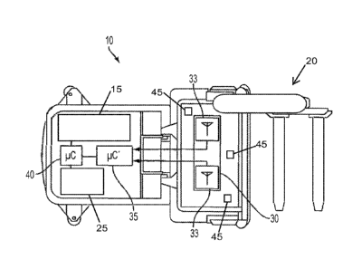
[0017] FIG. 1 illustrates an industrial vehicle 10 in the form of a lift
truck comprising
conventional industrial vehicle hardware, e.g., a steering mechanism 15,
storage and retrieval
hardware 20, and a vehicle drive mechanism 25, the details of which are beyond
the scope of
the present disclosure and may be gleaned from conventional and yet-to-be
developed
teachings in the industrial vehicle literature - examples of which include US
Pat. Nos.
6,135,694, RE37215, 7,017,689, 7,681,963, 8,131,422, and 8,718,860, each of
which is
assigned to Crown Equipment Corporation.
[0018] The industrial vehicle's 10 RFID system will typically include the
reader
module 35 and the tag reader 30. The tag reader 30 is configured to cooperate
with the reader
module 35 to identify at least one diagnostic tag 45 and one or more tags 5
(FIG. 2A) of a tag
layout in an environment such as a building, warehouse, or industrial facility
for example. It
should be understood that the reader module 35 may be a separate device or
part of the tag
reader 30. The industrial vehicle 10 further comprises a vehicle controller
40. For example,
and not by way of limitation, it is contemplated that the tag reader 30 will
be responsive to
UM tags positioned in the vicinity of the industrial vehicle 10. It is
contemplated that the
RFID tags are exclusively or a combination of passive RFID tags and active a
RFID tags. The
particular configuration of the reader module 35, the tag reader 30, and the
associated RFID
tags (hereinafter "tag") to which they are responsive are beyond the scope of
the present
disclosure and may be gleaned from conventional or yet-to-be developed
teachings on the
subject - examples of which include US Pat. Nos. 8,193,903 B2, assigned to
Crown
Equipment Corporation, and entitled "Associating a transmitter and a receiver
in a
supplemental remote control system for materials handling vehicles" and
6,049,745, assigned
to FMC Corporation, and entitled "Navigation System for Automatic Guided
Vehicle."
CA 02984795 2017-3.1-01
WO 2016/179526 PCT/US2016/031278
-4-
[0019] The tag reader 30 comprises one or more read antennas 33. Although
two are
shown in FIG. 1, it should be understood that any number of read antennas 33
are
contemplated. It is contemplated that each read antenna 33 reads tags within a
read range R
(FIG. 2A) (i.e., a distance between a read antenna 33 and a tag at which a
signal strength is
sufficient for the reader module 30 to identify the tag) and generates
respective tag read
signals when tags are within the read range of the read antennas 33. If there
are two or more
read antennas 33, than it is contemplated that the respective read ranges of
the read antennas
33 may overlap or be mutually exclusive. If the read ranges of the read
antennas 33 overlap,
it is contemplated that the tag reader 30 and the reader module 35 are
equipped to
discriminate between respective tag read signals from the different read
antennas 33 and
determine which tag read signal from which read antenna 33 is valid. In one
embodiment,
validity of the tag read signal is determined based on a comparison of a
signal strength of a
tag read signal by each read antennas 33 with the valid read antenna 33
determined to have
the stronger (i.e., greater magnitude) signal strength from the tag. In one
embodiment,
validity of the tag read signal is determined based upon which read antenna 33
generates the
tag read signal first.
[0020] The industrial vehicle 10 also comprises at least one diagnostic tag
45. In one
embodiment, there is one diagnostic tag 45 within a respective read range for
each read
antenna 33 on the industrial vehicle 10. In one embodiment, there is one
diagnostic tag 45
positioned on the industrial vehicle 10 such that it resides within the read
range of every read
antenna 33 on the industrial vehicle 10. The reader module 35 discriminates
between the
individual tags of the tag layout and the diagnostic tag 45 and the individual
tags of the tag
layout. The reader module 35 correlates an identified individual tag of the
tag layout with tag
data and an identified diagnostic tag 45 with operation of the tag reader 30.
[0021] Still referring to FIG. 1, it is contemplated that each diagnostic
tag 45
comprises a unique identification code which is the subject of the tag read
signal generated
by the read antennas 33. It is contemplated that the unique identification
codes of the one or
more diagnostic tags 45 can be stored in memory of the reader module 30 where
they will be
used to identify each diagnostic tag 45 for the purpose of diagnostics of the
tag readers 30. It
is also contemplated that the unique identification codes for each diagnostic
tag 45 are stored
in the memory of the reader module 35 at a location where the reader module 35
may quickly
CA 02984795 2017-3.1-01
WO 2016/179526 PCT/US2016/031278
-5-
identify each diagnostic tag 45 and enhance the processing speed of the
diagnostic routine
described in greater detail below. Specifically, and referring to FIG. 8, a
Confidence Group
221 corresponds to thc unique identification codes for the diagnostic tags and
as illustrated, is
the first group read in the memory locations 200 of the reader memory 205. The
individual
tags of the tag layout correspond to data in a reset group 220, a default
group 230, one or
more aisle zone groups 210, and one or more function zone groups 215. It is
the tag read
signal which is correlated with the memory locations 200 to identify the
confidence tag and
the individual tags of the tag layout.
[0022] Referring to Figs. 1 and 2, the diagnostic tag 45 is coupled to an
antenna frame
34 and transmits a diagnostic signal which is received by a read antenna 33 of
the tag reader
30 which in turn is used to generate the tag read signal. The reader module 35
confirms that
the diagnostic signal from the diagnostic tag 45 is received and is within
normal operating
parameters. Normal operating parameters may include, but are not limited to,
received signal
strength, signal delay, waveform shape, and the like. Example signal strength
measurements
include, but are not limited to, approximately -45 dB to approximately ¨ 50
dB. In some
embodiments, it may be preferable to have a signal strength measurement of
approximately -
30 dB. In all embodiments, the received signal strength of the diagnostic tag
45 is set such
that it is above the signal noise of the RFID system but below the received
signal strength of
the individual tags of the tag layout. As explained in greater detail below,
this is so the tag
reader 30 can identify tags of the tag layout when the diagnostic tag is
active. In other words,
so the diagnostic signal does not mask the transmit signals of the individual
tags of the tag
layout.
[0023] Referring to FIG. 2A, in one embodiment, the tag reader 30 is
located within a
read range R of a tag 5 of a tag layout. The tag reader 30 is coupled to the
industrial vehicle
in this embodiment and the tag 5 is within the environment. Referring to FIG.
2B, in one
embodiment, a diagnostic tag 45 is mounted to the industrial vehicle 10 within
the read range
R. Referring to FIG. 2C, in one embodiment, a tag reader 30 may comprise the
read antenna
33 and an antenna frame 34. The read antenna 33 and the diagnostic tag 45 are
coupled to the
antenna frame 34 and the antenna frame 34 is coupled to the industrial vehicle
10. In this
embodiment, the diagnostic tag 45 is coupled spatially between the read
antenna 33 and the
antenna frame 34. Examples of mounting locations on the industrial vehicle 10
include, but
CA 02984795 2017-3.1-01
WO 2016/179526 PCT/US2016/031278
-6-
are not limited to, the undercarriage, the body, bumpers, the storage and
retrieval hardware
20, and/or the protective cage.
[0024] Referring to FIG. 9, in one embodiment, the diagnostic tag 45 is a
passive
RFID tag comprising an antenna circuit 82 communicatively coupled to a data
chip 83. The
reader module 35 is coupled to the antenna circuit 82 and modulates power to
the diagnostic
tag 45 by applying power (direct current (DC) voltage) to the antenna circuit
82 such that the
antenna circuit 82 will not either receive electromagnetic radiation from the
tag reader 30 and
energize the data chip 83 or transmit the diagnostic signal. It is
contemplated that the reader
module 35 will apply power to the diagnostic tag 45 to disable the diagnostic
tag 45 as
explained in greater detail below and will remove power from the diagnostic
tag 45 to enable
the diagnostic tag 45, thereby allowing the diagnostic tag 45 to behave as a
passive RFID tag.
[0025] Referring to FIG. 10, in one embodiment, the diagnostic tag 45 is an
active
RFID tag comprising the data chip 83 communicatively coupled to the antenna
circuit 82 and
coupled to a power circuit 84. The power circuit 84 powers the data chip 83
and the antenna
circuit 82 such that the active RFID tag responds to the tag reader 33 with
the diagnostic
signal. The reader module 35 is coupled to the power circuit 84 such that the
reader module
35 powers the diagnostic tag 45 through applying power to the power circuit
84. Therefore, it
is contemplated that the reader module 35 will apply power to the power
circuit 84 of the
diagnostic tag 45 to enable the diagnostic tag 45 and will remove power from
the power
circuit 84 of the diagnostic tag 45 to disable the diagnostic tag 45 as
explained in greater
detail below.
[0026] FIG. 3 is a block diagram of a RIFD system 80 with a diagnostic tag
45. The
diagnostic system 80 comprises the reader module 35, the tag reader 30, a
power source 47,
and the diagnostic tag 45. The power source 47 is coupled to the reader module
35 and the
diagnostic tag 45 and the reader module 35 is coupled to the tag reader 30.
The diagnostic
system 80 may be active or inactive based on whether power is enabled or
disabled to the
diagnostic tag 45. In this way, the power to the diagnostic tag 45 may be
modulated as
explained in greater detail below. The tag reader 30 is communicatively
coupled to the
diagnostic tag 45. For example, as discussed above, a diagnostic signal
transmitted by the
diagnostic tag 45 is received by the read antenna such that the tag reader 30
generates a tag
CA 02984795 2017-3.1-01
WO 2016/179526 PCT/US2016/031278
-7-
read signal. Further, the tag reader 33 may transmit electromagnetic energy of
a specified
frequency to energize an antenna circuit of a passive RFID diagnostic tag 45
to power it. In
one embodiment, the power source is coupled to the vehicle controller 40 (FIG.
1) instead of
the reader module 35. In this configuration, the reader module 35 and the
vehicle controller
40 cooperate to modulate power to the diagnostic tag 45. In one embodiment,
the power
source 47 is not present and the reader module 35 powers the diagnostic tag
using the power
provided to the reader module 35.
[0027] FIG. 4 depicts a diagnostic tag modulation routine 50 utilizing a
diagnostic tag
for diagnosing the operational state of the tag reader in an RFID system. The
diagnostic tag
modulation routine 50 starts by initializing 51 the tag readers. The
diagnostic tag modulation
routine 50 then waits 52 for confirmation that the tag readers are
initialized. It is
contemplated that confirmation may be provided by the reader module 30 (FIG.
1) or the tag
readers 33 (FIG. 1). The next step is to either transition the diagnostic
routing 50 to active 53
or inactive 54. The decision to transition between active 53 and inactive 54
is explained in
detail below. The diagnostic tag modulation routine 50 may be transitioned as
needed
between the active 53 and inactive 54 states. If the diagnostic tag modulation
routine 50 is
inactive 54, the diagnostic tag modulation routine 50 does not look for faults
with the RFID
system and waits until it is transitioned to the active 53 state. It is
contemplated that the
diagnostic tag modulation routine 50 may be inactive 54 due to the tag reader
identifying tags
of a tag layout or the industrial vehicle 10 is shutting down. In the active
state 53, the
diagnostic tag transmits a diagnostic signal with its unique identification
code. The reader
module looks for a fault 55, as described hereinafter, in the RFID system.
[0028] FIG. 5 depicts four diagnostic modes 70 for the diagnostic tag: an
always on
mode 71, a smart mode 72, a smart modulation mode 73, and an always off mode
74. The
four diagnostic modes 70 are waveforms of the transmission of the diagnostic
signal and
relate to whether the diagnostic tag is enabled or disable. It is contemplated
that the
wavefolins may not be transitioned between enabled and disabled at regular
intervals as
shown in FIG. 5 (square wave) and may be enabled for the duration of time or
disabled for
the duration of time. In the always on mode 71, the reader module will enable
or maintain
power to the diagnostic tag such that the diagnostic tag transmits its
diagnostic signal at
CA 02984795 2017-3.1-01
WO 2016/179526 PCT/US2016/031278
-8-
regular intervals. In the always off mode 74, the reader module will disable
or remove power
from the diagnostic tag such that the diagnostic tag does not transmit its
diagnostic signal.
[0029] In the smart mode 72, the reader module will disable the diagnostic
tag when
it receives a tag read signal from the tag reader indicative of a tag which is
not the diagnostic
tag within the read range of the tag reader. In the smart mode 72, the reader
module will
disable or remove power from the diagnostic tag for a read interval 75 when
the tag reader
receives a tag read signal from the tag reader indicative of another tag in
the tag layout. It
should be understood that the read interval 75 is indicative of the start of
the interval and not
the duration of the interval. Therefore, the read interval 75 may have a
duration last as long as
needed until a tag, other than the diagnostic tag, is no longer identified by
the tag reader, a
delay timer elapses as explained below, or receive a transmitted signal from
another tag
which is not the diagnostic tag.
[0030] It is contemplated that the power to the diagnostic tag may be
modulated such
that the diagnostic signal transmitted by the diagnostic tag does not
interfere with the
standard operation of the industrial vehicle and the tag reader or to conserve
power.
Specifically, the tag reader may be used by the industrial vehicle to identify
one or more
individual tags in a tag layout in an environment such as a building. The
diagnostic tag's
transmitted diagnostic signal may interfere with or mask the transmitted
signal from the
individual tags of the tag layout while in operation. To prevent or at least
reduce the
likelihood of masking a signal from another tag, the reader module will
disable or remove
power from the diagnostic tag at periodic or regular intervals 76 to "listen
for" another tag as
shown in the smart modulation mode 73. When the diagnostic tag is disabled,
the reader
module will try to identify other tags or wait for a tag read signal from the
tag reader which is
indicative of a tag, which is not the diagnostic tag. It is contemplated that
the smart
modulation mode 73 will operate like the smart mode 72 wherein the diagnostic
tag is
disabled during the read interval 75 in addition to the regular intervals 76.
[0031] FIG. 6 depicts a diagnostic routine 60. The diagnostic routine 60
begins in an
initialize 63 state and initialize state machine variables and start the
diagnostic tag
modulation routine 50 (FIG. 3). Once variables and the tag readers are
initialized, the
diagnostic tag modulation routine 50 is set to inactive 54. Once the variables
are initialized,
CA 02984795 2017-3.1-01
WO 2016/179526 PCT/US2016/031278
-9-
the diagnostic routine 60 is transitioned to one of three states: a wait 65
state; an always on 61
state; or an always off 62 state. In the always on 61 state, the diagnostic
tag is enabled (i.e.,
powered) and the diagnostic tag modulation routine 50 (FIG. 4) is set to
active 53 (FIG. 4)
and always on 71 (FIG. 5) mode. It is contemplated that the diagnostic routine
60 will stay in
the always on 61 state until either a fault is identified or the industrial
vehicle is shut down. If
a fault is identified in the always on 61 state with the RFID system, the
diagnostic routine 60
will transition to an always off 62 state. In the always off 62 state,
diagnostic tag modulation
routine 50 is transitioned to the inactive 54 (FIG. 4) state, the diagnostic
tag is disabled (i.e.,
powered disconnected from the diagnostic tag), and the diagnostic mode 70 is
transitioned to
the always off 74 (FIG. 5) mode. A missing tag signal is generated when the
diagnostic
routine 60 transitions to the always off 62 state unless it is transitioned to
the always off 61
state from the initialize 63 state. If neither the always on 61 state nor the
always off 62 state
are chosen, the diagnostic routine 60 transitions to the wait 65 state to wait
for a tag read
signal.
[0032] The missing tag signal is generated when a fault is identified by
the diagnostic
routine 60. A fault includes, but is not limited to, signal parity,
attenuation, serial faults, tag
reader faults, and other types of system degradation or errors which may
affect system
operation and performance of the RFID system. In other words, the reader
module is
checking to see if a tag read signal is generated upon the tag reader's
identification of the
diagnostic tag and/or if the receipt of the diagnostic signal from the
diagnostic tag is
degraded, exhibits any signal parity or attenuation issues, or is otherwise
not within specific
operating parameters. Operating parameters include, but are not limited to,
received signal
strength of the received diagnostic signal, signal delay between transmission
of the received
signal by the diagnostic tag and receipt of the received signal by the tag
reader, waveform
shape of the received signal, signal parity, signal attenuation, or
combinations thereof.
[0033] A tag read signal generated by the tag readers, which is not derived
from the
diagnostic tag, is indicative that the tag readers are within a read range of
a tag of the tag
layout and are identifying 64 that tag of the tag layout. When a tag is
identified 64, the
diagnostic tag is disabled, the diagnostic tag modulation routine 50 is
transitioned to the
inactive 54, and the diagnostic mode 70 is transitioned to the always off 62
mode. A delay
timer may be used for a quantity of time (i.e., delay time) after a tag read
signal is generated
CA 02984795 2017-3.1-01
WO 2016/179526 PCT/US2016/031278
-10-
to wait and identify if another tag read signal is generated by the tag
readers for another tag of
the tag layout. It is contemplated that the delay timer may be started after a
tag read signal
generated by the tag readers subsequently stops due to the tag of the tag
layout lying outside
the read range of the tag readers. In other words, as the industrial vehicle
moves within the
read range of a tag of the tag layout, the tag readers generate the tag read
signal for the
duration of time the tag of the tag layout is identified. However, once the
industrial vehicle
moves beyond the read range of the tag of the tag layout, the tag read signal
ceases or is no
longer generated and the delay timer is started. It is contemplated that the
quantity of time of
the read interval 75 (FIG. 5) is defined by how may tag read signals are
generated and the
subsequent delay timer.
[0034] Once the delay timer elapses, the diagnostic routine 60 will
transition to the
wait 65 state for the next tag read signal to be generated by the tag readers.
In the wait 65
state, the diagnostic tag is enabled, the diagnostic tag modulation routine 50
is transitioned to
active 53, and the diagnostic mode 70 is set to the smart modulation mode 73.
In the wait 65
state, a modulation timer is used for a quantity of time (i.e., modulation
time) to wait and see
if a tag read signal is generated for a tag of the lag layout. If a tag read
signal is generated in
the wait 65 state, the diagnostic routine 60 is transitioned to the identify
64 state. It is
contemplated that the quantity of time of the regular interval 76 (FIG. 5) is
defined by how
may tag read signals are generated and the subsequent delay timer. It is in
the wait 65 state
and the always on 61 state in which the reader module is looking for a fault
in the RFID
system through the use of the diagnostic tag.
[0035] If a tag read signal is not generated in the wait 65 state and the
modulation
timer elapses, the diagnostic routine 60 transitions to a turn off diagnostics
66 state. In the
turn off diagnostics 66 state, the diagnostic tag is disabled, the diagnostic
tag modulation
routine 50 is transitioned to inactive 54, the diagnostic mode 70 is
transitioned to either the
smart mode 72 or the smart modulation mode 73 (FIG. 5) to look for a tag and
the
modulation timer is reset and started again. In the turn off diagnostics 66
state, it is
contemplated that either the industrial vehicle is in a location where there
aren't any tags of
the tag layout or that something has changed in the system such that the
diagnostic tag is the
only tag for which a tag read signal is generated. The turn off diagnostics
state 66 allows the
tag reader and reader module to identify outside factors that may lead to a
misidentification
CA 02984795 2017-3.1-01
WO 2016/179526 PCT/US2016/031278
-11-
of a fault. If the modulation timer elapses, the diagnostic routine 60 is
transitioned to the wait
65 state. If a tag read signal is generated for a tag of the tag layout during
the turn of
diagnostics 66 state, the diagnostic routine 60 is transitioned to the
identify 64 state.
[0036] If a fault is identified in the identify 66, wait 65, or turn off
diagnostic 66 state,
the diagnostic routine 60 is transitioned to the always off 62 state. In the
always off 62 state
and in the fault state 55 (FIG. 4), a missing tag signal is generated. For
example, and not by
way of limitation, if the reader module identifies a fault in the received
diagnostic signal, the
generated tag read signal, or does not identify the diagnostic tag, the reader
module will stop
the diagnostic routine 60 and generate a missing tag signal. Examples of
faults include, but
not limited to, serial communication degradation or failure, tag reader
degradation or failure,
or a modulation or delay timer exceeds a count threshold waiting for the
diagnostic tag to
transmit its signal or a generated tag read signal.
[0037] It is contemplated that when the missing tag signal is generated,
the vehicle
controller 40 (FIG. 1) may reduce a traveling speed of the vehicle drive
mechanism 25 (FIG.
1) to zero. In other words, it is contemplated that when a missing tag signal
is generated, the
vehicle controller 40 will bring the industrial vehicle 10 to a stop. The
vehicle controller 40
may transition the vehicle drive mechanism 25 to neutral after bringing the
industrial vehicle
to a stop. To clear the fault state, a user, may be required, using a user
interface, to
transition the vehicle drive mechanism 25 from neutral. For example, and not
by limitation,
the user of the industrial vehicle 10 may need to manually control the
industrial vehicle 10 as
automatic functionality is disabled while the missing tag signal is generated.
[0038] In one embodiment, the diagnostic routine 60 comprises a toggle mode
68 and
a service mode 67. The toggle mode 68 enables the diagnostic routine 60 to
switch diagnostic
testing between two or more read antennas such that only one read antenna is
enabled at a
time. In other words, the diagnostic routine 60 will look for a fault with a
first antenna and
then look for a fault with a second antenna. For example, and not by way of
limitation, if the
industrial vehicle comprises two tag readers, each with a respective
diagnostic tag, the
diagnostic routine 60 will look for and identify any problems with the tag
read signal and the
receipt of the diagnostic signal of the first tag reader while the second tag
reader is disabled.
Once testing of the first tag reader is accomplished, the first tag reader is
disabled and the
CA 02984795 2017-3.1-01
WO 2016/179526 PCT/US2016/031278
-12-
second tag reader is enabled and tested. It is contemplated that the toggle
mode is used in the
wait 65 state and the always on 61 state.
[0039] The service mode 67 enables the diagnostic routine 60 to go through
its steps
without generating a missing tag signal and faulting the industrial vehicle.
This may be
advantageous when the industrial vehicle is being serviced such that the RFID
system can be
tested without placing the industrial in a fault. An indication may be given
on a user interface
that the diagnostic routine 60 identified a fault without the generation of
the missing tag
signal.
[0040] It is contemplated that the embodiments described herein are not
limited to
only an industrial vehicle and may be used with many RFID devices. For
example, and not by
limitation, the RFID devices include a handheld RFID device. RFID security
systems, RFID
entry reader, and the like. In one embodiment and referring to FIG. 7A, the
RFID system 90
comprises a diagnostic tag 45 and a RFID reader 91. The diagnostic tag 45 is
coupled to the
RFID reader 91 within a read range R of an antenna 33 of the RFID reader 91. A
fault in the
RFID system 90 may be indicated by a flashing light 95, an audible tone from a
sound device
96, and/or disabling the RFID reader 91 until repairs or made or reset. In one
embodiment
and referring to FIG. 7B, the RFID system 90 comprises one or more diagnostic
tags 45 and
one or more RFID gates 92. Each diagnostic tag 45 is coupled to a RFID gates
92 within a
read range R of each antenna 33 of each RFID gate 92. A fault in the RFID
system 90 may be
indicated by one or more flashing lights 95, an audible tone from one or more
sound devices
96, and/or disabling the RFID gates 92 until repairs or made or reset. In one
embodiment and
referring to FIG. 7C, the RFID system 90 comprises a diagnostic tag 45 and a
RFID entry
reader 93. The diagnostic tag 45 is coupled to the RFID entry reader 93 within
a read range R
of an antenna 33 of the RFID entry reader 93. A fault in the RFID system 90
may be
indicated by a flashing light 95, an audible tone from a sound device 96,
and/or disabling the
RFID entry reader 93 until repairs or made or reset.
[0041] The present disclosure presents an apparatus and a process to
confirm the
operational status of a RFID system. The apparatus and process are used to
check for a fault
which include, but is not limited to, signal parity, attenuation, serial
faults, tag reader faults,
and other types of system degradation or errors which may affect system
operation and
CA 02984795 2017-3.1-01
WO 2016/179526 PCT/US2016/031278
-13-
perfoimance of the RFID system. A missing tag signal is generated if a fault
is identified. A
diagnostic tag may be mounted within a signal range of an antenna of a tag
reader and used to
provide an end-to-end test of the RFID system. The diagnostic tag may be
configured to
operate in one of several modes so that the diagnostic tag does not interfere
with the
operation of the RFID system when identifying tags in an environment. A
diagnostic routine
may be used if the tag readers no longer identify tags of a tag layout to
check the operation of
the system or routinely during operation to shutdown the industrial vehicle
upon an identified
fault.
[0042] Having described the subject matter of the present disclosure in
detail and by
reference to specific embodiments thereof, it is noted that the various
details disclosed herein
should not be taken to imply that these details relate to elements that are
essential
components of the various embodiments described herein, even in cases where a
particular
element is illustrated in each of the drawings that accompany the present
description. Further,
it will be apparent that modifications and variations are possible without
departing from the
scope of the present disclosure, including, but not limited to, embodiments
defined in the
appended claims. More specifically, although some aspects of the present
disclosure are
identified herein as preferred or particularly advantageous, it is
contemplated that the present
disclosure is not necessarily limited to these aspects.
[0043] It is noted that recitations herein of "at least one" component,
element, etc., or
"one or more" component, element, etc., should not be used to create an
inference that the
alternative use of the articles "a" or "an" should be limited to a single
component, element,
etc.
[0044] It is noted that the terms "substantially" and "about" may be
utilized herein to
represent the inherent degree of uncertainty that may be attributed to any
quantitative
comparison, value, measurement, or other representation. These terms are also
utilized
herein to represent the degree by which a quantitative representation may vary
from a stated
reference without resulting in a change in the basic function of the subject
matter at issue.
[0045] The phrase "communicably coupled" means that components are capable
of
exchanging data signals with one another such as, for example, electrical
signals via
CA 02984795 2017-3.1-01
WO 2016/179526 PCT/US2016/031278
-14-
conductive medium, electromagnetic signals via air, optical signals via
optical waveguides,
and the like.
[0046] It is noted that, while the functions are enumerated and depicted as
being
performed in a particular sequence in the depicted embodiment, the functions
can be
performed in an alternative order without departing from the scope of the
present disclosure.
It is furthermore noted that one or more of the functions can be omitted
without departing
from the scope of the embodiments described herein. .
[0047] While particular embodiments have been illustrated and described
herein, it
should be understood that various other changes and modifications may be made
without
departing from the spirit and scope of the claimed subject matter. Moreover,
although
various aspects of the claimed subject matter have been described herein, such
aspects need
not be utilized in combination. It is therefore intended that the appended
claims cover all
such changes and modifications that are within the scope of the claimed
subject matter.