Note: Descriptions are shown in the official language in which they were submitted.
Sliding Sleeve Having Indexing Mechanism and Expandable Sleeve
CROSS-REFERENCE TO RELATED APPLICATIONS
BACKGROUND OF THE DISCLOSURE
100021 In a staged fracturing operation, multiple zones of a formation need
to be isolated
sequentially for treatment. To achieve this, operators install a fracturing
assembly down
the wellbore, which typically has a top liner packer, open hole packers
isolating the
wellbore into zones, various sliding sleeves, and a wellbore isolation valve.
When the
zones do not need to be closed after opening operators may use single shot
sliding sleeves
for the fracturing treatment. These types of sleeves are usually ball-actuated
and lock open
once actuated. Another type of sleeve is also ball-actuated, but can be
shifted closed after
opening.
[0003] Initially, operators run the fracturing assembly in the wellbore
with all of the
sliding sleeves closed and with the wellbore isolation valve open. Operators
then deploy a
setting ball to close the wellbore isolation valve. This seals off the tubing
string of the
assembly so the packers can be hydraulically set. At this point, operators rig
up fracturing
surface equipment and pump fluid down the wellbore to open a pressure-actuated
sleeve
so a first zone can be treated.
[0004] As the operation continues, operates drop successively larger balls
down the
tubing string and pump fluid to treat the separate zones in stages. When a
dropped ball
meets its matching seat in a sliding sleeve, the pumped fluid forced against
the seated ball
shifts the sleeve open. In turn, the seated ball diverts the pumped fluid into
the adjacent
zone and prevents the fluid from passing to lower zones. By dropping
successively
increasing sized balls to actuate corresponding sleeves, operators can
accurately treat each
zone up the wellbore.
[0005] Figure 1A shows an example of a sliding sleeve 10 fora multi-zone
fracturing
system in partial cross-section in an opened state. This sliding sleeve 10 is
similar to
Weatherford's ZoneSelect MultiShift fracturing sliding sleeve and can be
placed between
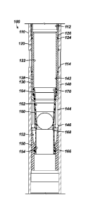
CA 2984951 2019-04-02
CA 02984951 2017-11-02
WO 2016/200819 PCT/US2016/036228
2
isolation packers in a multi-zone completion. The sliding sleeve 10 includes a
housing 20
defining a bore 25 and having upper and lower subs 22 and 24. An inner sleeve
or insert
30 can be moved within the housing's bore 25 to open or close fluid flow
through the
housing's flow ports 26 based on the inner sleeve 30's position.
[0006] When initially run downhole, the inner sleeve 30 positions in the
housing 20 in a
closed state. A breakable retainer 38 initially holds the inner sleeve 30
toward the upper
sub 22, and a locking ring or dog 36 on the sleeve 30 fits into an annular
slot within the
housing 20. Outer seals on the inner sleeve 30 engage the housing 20's inner
wall above
and below the flow ports 26 to seal them off.
[0007] The inner sleeve 30 defines a bore 35 having a seat 40 fixed
therein. When an
appropriately sized ball B lands on the seat 40, the sliding sleeve 10 can be
opened when
tubing pressure is applied against the seated ball B to move the inner sleeve
30 open. To
open the sliding sleeve 10 in a fracturing operation once the appropriate
amount of
proppant has been pumped into a lower formation's zone, for example, operators
drop an
appropriately sized ball B downhole and pump the ball B until it reaches the
landing seat
40 disposed in the inner sleeve 30.
[0008] Once the ball B is seated, built-up pressure forces against the
inner sleeve 30 in
the housing 20, shearing the breakable retainer 38 and freeing the lock ring
or dog 36 from
the housing's annular slot so the inner sleeve 30 can slide downward. As it
slides, the inner
sleeve 30 uncovers the flow ports 26 so flow can be diverted to the
surrounding formation.
The shear values required to open the sliding sleeves 10 can range generally
from 1,000 to
4,000 psi (6.9 to 27.6 MPa).
[0009] Once the sleeve 10 is open, operators can then pump proppant at high
pressure
down the tubing string to the open sleeve 10. The proppant and high pressure
fluid flows
out of the open flow ports 26 as the seated ball B prevents fluid and proppant
from
communicating further down the tubing string. The pressures used in the
fracturing
operation can reach as high as 15,000-psi.
[0010] After the fracturing job, the well is typically flowed clean, and
the ball B is floated
to the surface. Then, the ball seat 40 (and the ball B if remaining) is milled
out. The ball
seat 40 can be constructed from cast iron to facilitate milling, and the ball
B can be
composed of aluminum or a non-metallic material, such as a composite. Once
milling is
complete, the inner sleeve 30 can be closed or opened with a standard "B"
shifting tool on
CA 02984951 2017-11-02
WO 2016/200819 PCT/US2016/036228
3
the tool profiles 32 and 34 in the inner sleeve 30 so the sliding sleeve 10
can then function
like any conventional sliding sleeve shifting with a "B" tool. The ability to
selectively open
and close the sliding sleeve 10 enables operators to isolate the particular
section of the
assembly.
[0011] Because the zones of a formation are treated in stages with the
sliding sleeves 10,
the lowermost sliding sleeve 10 has a ball seat 40 for the smallest ball size,
and
successively higher sleeves 10 have larger seats 40 for larger balls B. In
this way, a specific
sized ball B dropped in the tubing string will pass though the seats 40 of
upper sleeves 10
and only locate and seal at a desired seat 40 in the tubing string. Despite
the effectiveness
of such an assembly, practical limitations restrict the number of balls B that
can be
effectively run in a single tubing string.
[0012] Depending on the pressures applied and the composition of the ball B
used, a
number of detrimental effects may result. For example, the high pressure
applied to a
composite ball B disposed in a sleeve's seat 40 that is close to the ball's
outer diameter can
cause the ball B to shear right through the seat 40 as the edge of the seat 40
cuts off the
sides of the ball B. Accordingly, proper landing and engagement of the ball B
and the seat
40 restrict what difference in diameter the composite balls B and cast iron
seats 40 must
have. This practical limitation restricts how many balls B can be used for
seats 40 in an
assembly of sliding sleeves 10.
[0013] In general, a fracturing assembly using composite balls B may be
limited to
thirteen to twenty-one sliding sleeves depending on the tubing size involved.
For example,
a tubing size of 5-1/2-in, can accommodate twenty-one sliding sleeves 10 for
twenty-one
different sized composite balls B. Differences in the maximum inner diameter
for the ball
seats 40 relative to the required outside diameter of the composite balls B
can range from
0.09-in, for the smaller seat and ball arrangements to 0.22-in, for the larger
seat and ball
arrangements. In general, the twenty-one composite balls B can range in size
from about
0.9-in, to about 4-in, with increments of about 0.12-in between the first
eight balls, about
0.15-in, between the next eight balls, about 0.20-in between the next three
balls, and about
0.25-in, between the last two balls. The minimum inner diameters for the
twenty-one seats
40 can range in size from about 0.81-in, to about 3.78-in, and the increments
between them
can be comparably configured as the balls B.
4
[0014] When aluminum balls B are used, more sliding sleeves 10 can be used
due to the
close tolerances that can be used between the diameters of the aluminum balls
B and iron
seats 40. For example, forty different increments can be used for sliding
sleeves 10 having
solid seats 40 used to engage aluminum balls B. However, an aluminum ball B
engaged in a
seat 40 can be significantly deformed when high pressure is applied against
it. Any
variations in pressuring up and down that allow the aluminum ball B to seal
and to then
float the ball B may alter the shape of the ball B compromising its sealing
ability.
Additionally, aluminum balls B can be particularly difficult to mill out of
the sliding sleeve
due to their tendency of rotating during the milling operation. For this
reason,
composite balls B are preferred.
[0015] Due to the limitations associated with conventional sliding sleeves,
stimulation
sleeves, such as the 1-ball from Weatherford, have been developed that use an
indexing
mechanism allowing the use of one ball size to operate multiple sleeve.
Details of this type
of stimulation sleeve are disclosed in US 2013/0186644 and US 8,701,776.
[0016] Although the many types of sleeves used in the art are effective,
operators
continually seek solutions that do not allow for flow to bypass around a
seated hall because
operators continually seek to limit treatment fluid from flowing past the
seated ball into
the zones below. To that end, the subject matter of the present disclosure is
directed to
overcoming, or at least reducing the effects of, one or more of the problems
set forth above.
SUMMARY OF THE DISCLOSURE
[0017] A downhole tool is disposed on tubing and is operable with pressure
applied
against one of a plurality of plugs deployed in the tool. The tool comprises
an insert, an
insert, a sleeve, and an indexing mechanism. The insert is disposed in the
tool and is
movable from a first position toward a second position. The sleeve is disposed
in the tool,
is engageable with the deployed plugs, and is movable with the engagement. The
sleeve is
expansive in an absence of external support and releases the engaged plug in
response to
the expansion.
[0018] The indexing mechanism is disposed in the tool and is operable
between the
sleeve and the insert. In response to the engagement with the deployed plugs,
the indexing
mechanism moves with the sleeve and counts the engagements. la response to a
predetermined count of the engagements, the indexing mechanism forms the
external
CA 2984951 2019-04-02
CA 02984951 2017-11-02
WO 2016/200819 PCMJS2016/036228
support of the one deployed plug and moves the insert from the first position
toward the
second position with the pressure applied against the one deployed plug, which
is engaged
in the sleeve and is supported by the indexing mechanism.
[0019] For example, the downhole tool can be a sliding sleeve tool disposed
on a tubing
downhole. The sliding sleeve tool can open with one of a plurality of plugs
deployed down
the tubing. In this case, the tool can have a housing that defines a first
bore and that
defines a flow port communicating the first bore outside the housing. The
insert is
disposed in the first bore of the housing and defines a second bore
therethrough for
passage of the plugs. The sleeve is also disposed in the first bore of the
housing and defines
a third bore therethrough for passage of the plugs. The insert is movable
inside the first
bore from a closed position to an opened position relative to the flow port.
[0020] In the tool, the indexing mechanism operable between the sleeve and
the insert is
reciprocally movable in first and second opposite directions up to the
predetermined
count. The indexing mechanism is biased relative to a portion of the housing.
In this way,
the indexing mechanism counts the movement of the sleeve in the first
direction by the
engagement of one or more initial of the deployed plugs and resets in the
second direction
with the bias relative to the portion. The indexing mechanism at the
predetermined count
provides the external support for the engagement of a last of the deployed
plugs. The
portion of the tool can be a seat against which the indexing mechanism is
biased, and this
seat can be fixed in the tool or can be movable in the tool in the first
direction.
[0021] In one embodiment, the indexing mechanism comprises a collet
operable between
the sleeve and the insert. The collet has fingers biasing against a surface in
the first bore of
the housing. The collet is affixed to the sleeve. Thus, the sleeve moving in a
first direction
in the housing with the engagement of the deployed plug moves the collet in
the first
direction toward the surface. Likewise, the collet moving in a second
direction opposite to
the first direction by the bias of the fingers against the surface moves the
sleeve in the
second direction in the housing. The surface of the tool can be an inclined
surface of a seat
against which the collet fingers are biased. This seat can be fixed in the
tool or can be
movable (shiftable) in the tool in the first direction.
[0022] A pin and slot arrangement couples the collet to the insert and
allows movement
of the collet relative to the insert from a start position, to at least one
intermediate position,
and to a final position. In response to the engagement of a first of the
deployed plugs with
CA 02984951 2017-11-02
WO 2016/200819 PCMJS2016/036228
6
the sleeve, the pin and slot arrangement allows the collet to move in the
first direction
relative to the insert from the start position to a first stop position. The
fingers of the collet
in the first stop position leave the sleeve in the absence of the external
support.
[0023] In response to the release of the first deployed plug and with the
bias of the
fingers of the collet, the pin and slot arrangement allows the collet to move
in the second
direction relative to the insert from the first stop position to the at least
one intermediate
position. In response to the engagement of a second of the deployed plugs with
the sleeve,
the pin and slot arrangement allows the collet to move in the first direction
relative to the
insert from the at least one intermediate position to the final position; and
wherein the
fingers of the collet in the final position provide external support to the
sleeve to hold the
second deployed plug engaged therein.
[0024] In the tool, the sleeve comprises a restriction therein for engaging
with the
deployed plugs, and the restriction at least partially is longitudinally rigid
and radially
flexible. The sleeve comprises a tubular structure with a continuous wall
thereabout, the
restriction being a throat of reduced diameter formed around the continuous
wall.
[0025] According to the present disclosure, an apparatus is operable with a
plurality of
plugs deployed through tubing downhole in a borehole. The apparatus comprises
first and
second tools disposed on the tubing and configured to operate in response
respectively to a
first count and a second count of the deployed plugs. Each of the first and
second tools
comprises an insert, a sleeve, and an indexing mechanism as disclosed above.
As such, the
indexing mechanism operable between the sleeve and the insert of the tool
forms the
external support in response to the respective count.
[0026] According to the present disclosure, a method for tubing downhole in
a borehole
involves deploying one or more initial plugs downhole to a first tool on the
tubing. The
first tool indexes to a first count by reciprocally moving (shifting) a
radially expandable
sleeve in first and second opposite directions in the first tool with the one
or more first
plugs engaged therein and releasing the one or more initial plugs from the
radially
expandable sleeve. The method further involves deploying a subsequent plug
downhole to
the first tool indexed to the first count; and moving (shifting) the radially
expandable
sleeve in the first direction in the first tool with the subsequent plug
engaged therein. The
subsequent plug is held in the first tool by radially supporting the radially
expandable
CA 02984951 2017-11-02
WO 2016/200819 PCMJS2016/036228
7
sleeve, and an insert is actuated in the first tool in response to fluid
pressure applied
against the subsequent plug, which is held in the radially supported sleeve.
[0027] Indexing the first tool to the first count can involve guiding a pin
in a slot defined
between the insert and the radially expandable sleeve. Reciprocally moving the
sleeve can
involve biasing the sleeve in the second direction opposite to the movement
the sleeve in
the first direction by the engagements with the deployed plugs. Radially
supporting the
radially expandable sleeve can involve wedging collet fingers around the
radially
expandable sleeve with the shifting of the sleeve. Actuating the insert in the
first tool can
involve shifting the insert relative to a flow port communicating outside the
first tool.
[0028] The method can further involve indexing a second tool uphole of the
first tool to a
second count so an insert can be actuated in the second tool in response to
fluid pressure
applied against a following plug held in the radially supported sleeve.
[0029] The foregoing summary is not intended to summarize each potential
embodiment
or every aspect of the present disclosure.
BRIEF DESCRIPTION OF THE DRAWINGS
[0030] Fig. 1A illustrates a sliding sleeve according to the prior art
having a ball engaged
with a seat to open the sliding sleeve.
[0031] Fig. 1B illustrates a close up view of the sliding sleeve in Fig.
1A.
[0032] Fig. 2 illustrates a treatment assembly having a plurality of
sliding sleeve tools
according to the present disclosure.
[0033] Fig. 3A illustrates a sliding sleeve tool according to the present
disclosure in an
initial condition.
[0034] Fig. 3B illustrates the tool of Fig. 3A in a first intermediate
condition.
[0035] Fig. 3C illustrates the tool of Fig. 3A in a second intermediate
condition.
[0036] Fig. 3D illustrates the tool of Fig. 3A during a process of opening.
[0037] Fig. 3E illustrates the tool of Fig. 3A in an opened condition.
[0038] Fig. 4 illustrates a perspective view of the seating sleeve for the
disclosed tool.
[0039] Fig. 5 illustrates an elevational view of a lower end of the insert
of the tool
engaged with the upper end of the collet.
[0040] Fig. 6 illustrates a perspective view of the insert with its lower
end having a J-slot
profile.
CA 02984951 2017-11-02
WO 2016/200819 PCT/US2016/036228
8
[0041] Fig. 7 illustrates a perspective view of the collet with location of
the inner pin
depicted.
[0042] Figs. 8A-8C illustrate an alternative embodiment of the disclosed
tool during
opening.
DETAILED DESCRIPTION OF THE DISCLOSURE
[0043] Figure 2 shows a treatment assembly 50 having an arrangement of
sliding sleeve
tools (100A-C) according to the present disclosure. As shown, a tubing string
52 deploys in
a wellbore 54. The string 52 has the several sliding sleeve tools 100A-C
disposed along its
length, and various packers 70 may isolate portions of the wellbore 54 into
isolated zones.
In general, the wellbore 54 can be an opened or cased hole, and the packers 70
can be any
suitable type of packer intended to isolate portions of the wellbore 54 into
isolated zones.
[0044] The tools 100A-C can be used to divert treatment fluid, such as
fracture fluid,
selectively to the isolated zones of the surrounding formation. The tubing
string 52 can be
part of a fracturing assembly, for example, having a top liner packer (not
shown), a
wellbore isolation valve (not shown), and other packers and sleeves (not
shown) in
addition to those shown. If the wellbore 54 has casing then the wellbore 54
can have
casing perforations 56 at various points.
[0045] As conventionally done, operators deploy a setting ball (not shown)
to close a
wellbore isolation valve (not shown) positioned lower downhole on the tubing
string 52.
Indexing mechanisms 130 in each of the tools 100A-C allow the setting ball to
pass
therethrough. Then, operators rig up fracturing surface equipment 65 and pump
fluid
down the wellbore 54 to open a pressure actuated sleeve (not shown) toward the
end of
the tubing string 52. This treats a first zone of the wellbore 54.
[0046] In later stages of the operation, operators successively actuate the
tools 100A-C to
treat the isolated zones. In particular, operators deploy plugs B (e.g., balls
or the like)
down the tubing string 52. Each plug B can be the same size and can be
configured to seat
in any one of the tools 100A-C once the sleeve's indexing mechanism 130 has
been
activated to a final state after counting successively passed plugs B. In
general, the tools
100A-C are activated uphole along the tubing string 52 in successive stages so
that the
successive intervals up the wellbore 54 can be treated. When not in the final
state, the
indexing mechanisms 130 of the tools 100A-C can pass those plugs B intended
for lower
tools 100A-C.
CA 02984951 2017-11-02
WO 2016/200819 PCMJS2016/036228
9
[0047] As will be described in more detail below, features of the indexing
mechanism 130
use a seating sleeve and a collet to engage and count deployed plugs B. As
configured,
these components either reset to an intermediate state to engage one or more
successive
plugs B, or these components activate to a final state in response to a
predetermined count
of the deployed plugs B in the given tool 100A-C. Once the components are
activated to the
final state, the tools 100A-C engages the deployed plug B and can be opened
with applied
fluid pressure.
[0048] With a general understanding of the disclosed tool 100 and the
assembly 50 in
which it can be used, discussion now turns to an embodiment of a sliding
sleeve tool
according to the present disclosure.
[0049] Fig. 3A illustrates an embodiment of a sliding sleeve tool 100
according to the
present disclosure in an initial condition. The tool 100 can be part of a
multi-zone
fracturing system, such as discussed previously, that uses the tool 100 to
open and close
communication with a borehole annulus. In such an assembly, the tool 100 can
be placed
on tubing string between isolation packers in the multi-zone completion.
[0050] The tool 100 includes a housing 110 with an inner bore 112 and one
or more ports
114. Upper and lower ends of the housing 110 can coupled to tubing components
of a
tubing string in a conventional manner and are not shown here. An inner sleeve
or insert
120 can move axially within the housing's bore 122 to open or close fluid flow
through the
housing's ports 114 based on the insert 120's position. During operations, for
example, the
insert 120 is typically moved axially in a downward direction inside the bore
122 from a
closed position to an opened position relative to the flow ports 114.
[0051] The indexing mechanism 130 is coupled between a seating sleeve 160
and the
insert 120. In particular, the indexing mechanism 130 includes a collet 140
that can move
axially with the seating sleeve 160 in response to the engagement with the
deployed plugs
B. During operations, the collet 140 then acts as a spring to return the
indexing mechanism
130 to an intermediate state and eventually acts a support for the seating
sleeve 160 in a
final state. In this way, the indexing mechanism 130 allows for several same
size (or
various size) plugs B to pass through the tool 100 until a predetermined count
has been
reached.
[0052] When initially run downhole, the insert 120 positions in the housing
110 in a
closed state, as in Figure 3A. A retaining element 126, such as a conventional
shear ring,
CA 02984951 2017-11-02
WO 2016/200819 PCMJS2016/036228
can engage the insert 120 to temporarily hold the insert 120 toward the closed
condition
so outer seals 124 on the insert 120 engage the housing's bore 112 both above
and below
the flow ports 114 to seal them off.
[0053] The tool 100 is designed to open when a preconfigured number of one
or more
plugs (e.g., balls B) lands in the seating sleeve 160 and tubing pressure is
applied to actuate
the indexing mechanism 130 to count the preconfigured number of times.
(Although a ball
B is shown and described, any conventional type of plug, dart, ball, cone, or
the like may be
used. Therefore, the term "ball" as used herein is merely meant to be
illustrative.)
[0054] The seating sleeve 160 is attached at one end 164 to the collet
member 140. As
shown, an internal retainer 170 in the form of an inclined ring can be used to
affix this
sleeve's end 164 to the collet member 140. A second end 166 of the seating
sleeve 160
extends beyond the fingers 144 and the heads 146 of the collet member 140 and
engages
inside a seat member 150 held inside the housing's bore 112.
[0055] As shown, the seating sleeve 160 is generally cylindrical in nature
and defines an
internal passage 162 communicating the insert's passage 122 with the lower end
of the
seat member 150 and the housing's bore 112. The sleeve's internal passage 162,
however,
includes a restricted diameter or seating area 168 therein for engaging balls
deployed
through the passage 162 during operations as described below.
[0056] For further reference, Fig. 4 illustrates a perspective view of the
outside surface of
the disclosed seating sleeve 160. As shown from the exterior, the sleeve 160
come inward
to the restriction 168 of the inner passage (162) for engaging with the
deployed plugs. The
restriction 168 at least partially is axially rigid and radially flexible.
Preferably, the sleeve
160 is a tubular structure with a continuous wall thereabout so that the
restriction 168 is a
throat of reduced diameter formed around the continuous wall.
[0057] During operations as described in more detail below, the seating
sleeve 160 as
shown in Fig. 3A makes contact with a deployed plug B as the deployed plug B
enters the
sleeve's bore 162 and engages the seating area 168. When the plug B is
engaged, the
seating sleeve 160 is movable axially downward with the engagement of the plug
B, and the
translation actuates the spring collet member 140 and starts the count of the
indexing
mechanism 130.
[0058] The seating sleeve 160 can be composed of rubber or other semi-rigid
but flexible
material. For example, the seating sleeve 160 can be composed of any suitable
material,
CA 02984951 2017-11-02
WO 2016/200819 PCMJS2016/036228
11
such as an elastomer, a thermoplastic, an organic polymer thermoplastic, a
polyetheretherketone (PEEK), a thermoplastic amorphous polymer, a polyamide-
imide,
TORLON , a soft metal, etc., and a combination thereof. (TORLON is a
registered
trademark of SOLVAY ADVANCED POLYMERS L.L.C.)
[0059] The seating sleeve 160 preferably has solid walls to prevent any
erosion when
sand flows through the inside of the tool 100 during treatment. The seating
sleeve 160
serves as a dampening mechanism for the plugs B so that the plugs B do not
impact metal
edges. The seating sleeve 160 also serves as extra sealing support for the
plug B in its final
sequence discussed later.
[0060] Engaging the seating sleeve 160, the plug B creates a restriction
that moves the
seating sleeve 160 downward and collapses the support member of the collet's
fingers 144.
As long as the seating sleeve 160 remains externally unsupported, the seating
sleeve 160
can expand radially, especially at the seating area 168, in an absence of the
external
support. At this point, the seating sleeve 160 can thereby release the engaged
plug B from
the bore 162.
[0061] To engage and release, the seating sleeve 160 is radially expandable
at least when
a predetermined pressure is applied against the engaged ball B. The seating
sleeve 160
then expands to let the plug B through, and the collet's fingers 144 are in
turn used as a
spring to retract the indexing mechanism 130 to its next position.
[0062] At this point, the collet 140 and the seating sleeve 160 then
retract back to an
intermediate state to accept the next deployed plug B. This counting is
repeated until a
final plug B engages in the seating sleeve 160 and is prevented from passing
through the
seating sleeve 160 by the supported engagement of the collet 140. With the
final plug B
"caught" in the tool 100, the insert 120 can be opened to pass treatment fluid
from the
tubing string into the wellbore.
[0063] As can be seen in the above description, the indexing mechanism 130
counts the
engagement of the deployed plugs B, and the collet 140 forms external support
of the
seating sleeve 160 in response to a predetermined count. Once this count is
reached, the
collet 140 is coupled by the indexing mechanism 130 to move the insert 110
axially in the
housing's bore 112 from the closed condition to the open condition with
applied pressure
against the engaged plug B in the seating sleeve 160 supported by the collet
member 140.
CA 02984951 2017-11-02
WO 2016/200819 PCT/US2016/036228
12
[0064] Turning now to the particulars of the tool 100 as shown in Fig. 3A,
an inner
surface 142 on the upper end of the collet member 140 fits partially on an
external surface
128 on the lower end of the insert 120. The two surfaces 142, 128 can move
relative to one
another, and the collet member 140 and insert 120 can move independently of
one another
or together depending on the current configuration of the indexing mechanism
130 defined
between these two members 120, 140.
[0065] The indexing mechanism 130 in one embodiment includes a pin and slot
arrangement, such as a pin and 1-slot profile between the collet 140 and the
insert 120. For
example, Fig. 6 illustrates a perspective view of the insert 120 with its
lower end's surface
128 having a J-slot profile 132. More than one such profile 132 can be mapped
around the
surface 128, and the profile 132 can have any number of intermediate slot
positions other
than those particularly shown.
[0066] Moreover, Fig. 7 illustrates a perspective view of the collet 140
with a location of
the inner pin 134 depicted inside the collet's inner surface 142. When the
collet 140 is
assembled on the insert 120, the inner pin 134 can ride inside the external 1-
slot profile
132 mapped around the collet's surface 128, which controls relative movement
between
the collet 140 and the insert 120 when indexing and counting as discussed
below.
[0067] The pin and slot arrangement of the indexing mechanism 130 allows
relative and
coordinated movement between the collet 140 and the insert 120 from a start
position, to
at least one intermediate position, and to a final position. First axial
movement of the
sleeve 160 with the engagement of the deployed plug B in a first direction
moves the collet
140 downward relative to the insert 120, and second axial movement of the
collet 140 by
the bias of the fingers 144 in a second, opposite direction moves the sleeve
160 upward
relative to the insert 120.
[0068] Having an understanding of the components of the disclosed tool 100,
discussion
now turns to how the tool 100 operates to count the passages of balls B and
eventually
open to allow fluid flow through the open tool 100. To actuate the tool 100
while initially
in its closed position in Fig. 3A, operators drop a ball B downhole and
drop/pump the ball B
until it reaches the seating sleeve 160 disposed in the housing 110. The ball
B engages the
seating profile 168 in the seating sleeve 160, which creates a seal therewith.
Fluid pressure
behind the seated ball B then shifts the seating sleeve 160 axially downward
while the ball
B remains seated in the profile 168, as shown in Fig. 3B. As this occurs, the
shifting sleeve
CA 02984951 2017-11-02
WO 2016/200819 PCMJS2016/036228
13
160 retained by the retainer 170 to the collet 140 also shifts the collet 140
axially
downward with it. The heads 146 of the collet's fingers 144 meet the incline
152 of the
seat 150 which increases bias against the movement of the collet 140 and the
sleeve 160.
[0069] At the same time, the indexing mechanism 130 (having the pin 134 in
the J-slot
profile 132 best depicted in Fig. 5) controls the relative movement of the
collet 140 to the
insert 120. In general, the pin and slot arrangement of the indexing mechanism
130 allows
the collet 140 to move axially in a first direction with the engagement of a
first of the
deployed plugs B from the start position to a first stop position. Yet, the
fingers 144 of the
collet 140 in the first stop position leave the sleeve 160 unsupported
radially because the
heads 146 of the collet fingers 144 do not close fully around the seating area
168 of the
sleeve 160, as shown in FIG. 3B.
[0070] Eventually in the axial movement of the collet 140 downward relative
to the insert
120, the pin 134 reaches the first lower transition in the slot 132 so that
further downward
movement of the collet 140 ceases. The insert 120 does not open at this point
because (i)
the retention of the retaining feature 126 on the insert 120 is not overcome
even though
the collet 140 has reached its lower limit and pulls the insert 120 downward
with the pin
134 in the first lower transition of the slot profile 132, (ii) the bias of
the collet's fingers
144 resist further axial movement downward, and (iii) the inward flexibility
of the seating
sleeve's profile 168 remains still unsupported by the fingers' heads 146 and
gives way to
the pressure of the plug B being forced through the seating sleeve 160. As can
be seen in
Fig. 3B, the diameter of the plug B can expand the unsupported seating profile
168 of the
seating sleeve 160, and the released plug B can pass through the tool 100 with
the applied
pressure behind the plug B.
[0071] With the plug B free of the seating sleeve 160 as shown in Fig. 3C,
the bias of the
collet's fingers 144 then shifts the collet 140 axially upward as the fingers'
heads 146 ride
up the incline 152 of the seat 150. Thus, the pin and slot arrangement of the
indexing
mechanism 130 allows the collet 140 to move axially in a second, opposite
direction from
the first stop position to at least one intermediate position with the release
of the first
deployed plug B and with the bias of the fingers 144 of the collet 140.
Accordingly, the
collet 140 returns further onto the end of the insert 120. The movement is
guided by the
indexing mechanism 130, as the pin 134 travels from the first lower transition
upward in
the profile to the intermediate turnaround where the pin 134 rests.
CA 02984951 2017-11-02
WO 2016/200819 PCMJS2016/036228
14
[0072] The tool 100 is now ready to receive passage of the next plug B.
When deployed to
the tool 100 in its intermediate state in Fig. 3C, the plug B again seats on
the seating profile
168 so that the seating sleeve 160 can shift axially downward and move the
collet 140
along with it, guided by the indexing mechanism 130. This repeats the
positioning of the
components to the arrangement depicted in Fig. 3B. The plug B can then be
forced through
the seating profile 168 as before to pass further downhole, and the collet 140
and sleeve
160 can again return to another intermediate position as depicted in Fig. 3C.
This process
can be repeated any number of times depending on the transitions and
turnarounds
configured in the J-slot profile 132.
[0073] Eventually (and even after just passage of one plug B if so
configured), the
indexing mechanism 130 can position in its final intermediate position. For
instance as
shown in Fig. 5, the pin 134 of the collet 140 may reside in the final
turnaround on the J-
slot profile. Although the components of the tool 100 are arranged in the
configuration of
Fig. 3B to accept the next ball B, the collet 140 is configured to move one
last time axially
downward relative to the insert 120 guided by the pin 134 at the final
turnaround of the 1-
slot profile 132. Moreover, the collet 140 by virtue of its pin 134 in the
slot profile 132 is
configured to extend axially further from the insert 120 due to the longer
extent of the final
run on the profile 132.
[0074] Accordingly, the tool 100 is now ready to receive passage of the
final plug B to the
tool 100 in its final intermediate state similar to that depicted in Fig. 3C.
The plug B again
seats on the seating profile 162 so that the seating sleeve 160 can shift
axially downward
and move the collet 140 along with it. Rather than stopping partially along
the way, the
collet 140 moves further axially downward as its pin 134 rides further in the
last run of the
slot profile 132. As a result, the heads 146 of the collet fingers 144 come
further inward as
shown in Fig. 3D along the incline 152 of the seat 150, and the heads 146 now
support the
seating profile 168 of the sleeve 160 and further act to seat the ball B. In
this way, the
fingers 144 and the heads 146 of the collet 140 in the final position provide
radial support
to the radially-expandable seating sleeve 160 to hold the deployed plug B
engaged therein.
[0075] Pressure acting against the plug B can no longer force the plug B
through the now-
supported seating profile 168, and the acting pressure thereby pushes against
the seated
plug B and the seat 150. For its part, the seat 150 in one embodiment can be a
shiftable
component disposed in the housing 110. The applied pressure against the plug B
and the
CA 02984951 2017-11-02
WO 2016/200819 PCMJS2016/036228
seat 150 can then begin shifting the seat 150 in the housing 110 as shown in
Fig. 3E so that
the movement pulls the collet 140 and the insert 120. Eventually, the shear
force of the
retainer 126 is breached, and the insert 120 can shift open past the ports 114
in the
housing 110.
[0076] In this way, fluid pressure applied in the sleeve's bore 112 acts
against the seated
plug B. At the same time, the applied pressure against the seated plug B
forces the insert
120 in the bore 112 against the temporary retainer 126. Eventually, the
temporary
retainer 126 breaks, freeing the insert 120 to move in the bore 112 from the
closed
condition to the opened condition. In this and other tools 100 disclosed
herein, the shear
values required to open the tool 100 can range generally from 1,000 to 4,000
psi, although
any acceptable values can be used.
[0077] The tool 100 can now be used for fluid communication with the
surrounding
wellbore for communication treatment fluid, fracture fluid, etc. to the
wellbore outside the
open tool 100. For example, fracturing can then commence by flowing treatment
fluid,
such as a fracturing fluid, downhole to the tool 100 so the fluid can pass out
the open flow
ports 114 to the surrounding formation. The final plug B engaged in the
radially-supported
seating sleeve 160 prevents the treatment fluid from passing and isolates
downhole
sections of the assembly.
[0078] With the tool 100 is open, for example, operations begin pumping
higher pressure
treatment (e.g., fracturing fluid) downhole to the open tool 100. In this and
other
embodiments of tool 100 disclosed herein, the pressures used in the fracturing
operation
can reach as high as 15,000-psi. It should be noted that the support provided
by the seat
150, the seating sleeve 160, and the collet heads 146 does not need to be
entirely leak proof
because the fracturing treatment may merely need to sufficiently divert flow
with the
seated ball B and maintain pressures. Yet the additional engagement of the
plug B
provided by the seating sleeve 160 is intended to improve the fluid seal even
at higher
fracturing pressures.
[0079] As noted above, the seating sleeve 160 can be composed of a suitable
material,
including, but not limited to, an elastomer, a hard durometer rubber, a
thermoplastic such
as TORLON , a soft metal, an elastically deformable material, a plastically
deformable
material, PEEK, or a combination of such materials. The particular material
used and
durability of the material used for the sleeve 160 can be configured for a
given
CA 02984951 2017-11-02
WO 2016/200819 PCMJS2016/036228
16
implementation and expected pressures involved. Moreover, the selected
durability can be
coordinated with expected pressures to be used downhole during an operation,
such as a
fracturing operation, and can be coordinated with the configured breaking
point of the
retaining feature 126 or other temporary attachments used in the tool 100.
[0080] Once the treatment is complete for this tool 100, similar operations
can be
conducted uphole to treat other sections of the wellbore. After the fracturing
job is
completed, the well is typically flowed clean, and the plugs B are floated to
the surface.
Sometimes, the plugs B may not be floated or may not dislodge from the tool
100. Instead,
the plugs B can be dissolvable or the like. In any event, the seat 150,
seating sleeve 160,
and collet 140 (and the plug B if remaining) can be milled out to provide a
consistent inner
dimension of the tool 100. To facilitate milling, the seat 150 and the collet
140 can be
constructed from cast iron, and the plug B can be composed of aluminum or a
non-metallic
material, such as a composite.
[0081] Once milling is complete, the insert 120 can be closed or opened
with a shifting
tool. For example, the insert 120 can have tool profiles (not shown) so the
tool 100 can
function like any conventional sliding sleeve that can be shifted opened and
closed with a
convention tool, such as a "B" tool. Other arrangements are also possible.
[0082] In an alternative arrangement as shown in Figs. 8A-8C, the seat 150
may not be a
shiftable component. Instead, the incline 152 of the seat 150 may extend a
greater extent
and come together to a uniform profile, as shown in Fig. 8A. In the
intermediate position
shown in Fig. 8B, the heads 146 of the collet 140 can ride partially along the
incline 152 and
still not form external support for the sleeve 160 so that the plug B can
eventually expand
the seating sleeve 160 and pass out of the tool 100. In the final position
shown in Fig. 8C,
however, the heads 146 can slide further along the seat 150 by virtue of the
indexing
mechanism 130 and can then maintain a seat with the seating profile 168
against the plug
B. Movement of the collet 140 can in turn pull the insert 120 against the
retainer 126 and
eventually break it free. Yet, shifting of the seat 150 in the bore 112 of the
insert 110 does
not need to occur.
[0083] Although an implementation has been proposed in which the same size
plug B is
deployed downhole to index through multiple tools 100 and eventually actuate
one of the
tools 100 open, it will be appreciated that different sized plugs B can be
used for various
17
ones of the tools 100 with the seating components properly sized, and it will
he
appreciated that a combination of different and same sized plugs B can be
used.
[00841 Although the pin and slots arrangement for the indexing mechanism
130 as
disclosed above has the pin 134 situated on the collet 140 and has the J-slot
profile 132
defined on the insert 120, an opposite arrangement could be used with a pin
situated on
the insert 134 and a j-slot profile defined on the collet 140 in an inverted
orientation. In
other alternatives, the tool 100 can include a secondary indexing mechanism lo
expand the
counts. Also, the indexing mechanism 130 for the tool 100 can be radially
actuated.
[00851 Although the incline 152 of the seat 150 is depicted in some
embodiments as part
of the seat 150 and a separate component from the housing 110, this is not
strictly
necessary. Instead, portion of the housing 110 may have portion of the incline
152 for
engaging the heads 146 of the collet fingers 144. In embodiments where the
seat member
150 is not separately movable in the housing 110 as in the embodiments of
Figs. BA-8C, the
features of the seal member 150 can instead be integral to the housing 110.
[00861 It will be appreciated with the benefit of the present disclosure
that features
described above in accordance with any embodiment or aspect of the disclosed
subject
matter can be utilized, either alone or in combination, with any other
described feature, in
any other embodiment or aspect of the disclosed subject matter. Accordingly,
features and
materials disclosed with reference to one embodiment herein can be used with
features
and materials disclosed with reference to any other embodiment.
[00871
It is intended that the
appended claims include all modifications and alterations to the full extent
that they come
within the scope of the following claims or the equivalents thereof.
CA 2984951 2019-04-02