Note: Descriptions are shown in the official language in which they were submitted.
CA 02985034 2017-11-03
1
DESCRIPTION
Title of Invention
GAS ENGINE
Technical Field
[0001] The present invention relates to a gas engine capable of responding to
a change in
the calorific value of a fuel gas.
Background Art
[0002] In general, a control of the air-fuel ratio in a gas engine is set
corresponding to a
fuel gas having a fixed composition, but actually, a composition of a supplied
fuel gas is not
fixed.
[0003] In a conventionally disclosed configuration, an A/F valve and a
solenoid valve are
arranged in a fuel path, and a control is performed such that the average
opening degree of
the solenoid valve is settled to 50%, to perfoini stoichiometric combustion in
a gas engine
fueled by a gas having a variable calorific value (for example, see Patent
Literature 1 (PTL
1)).
Citation List
Patent Literature
[0004] PTL 1: Japanese Patent Application Laid-Open No. 2014-240616
Summary of Invention
Technical Problem
[0005] In the conventional gas engine described above, however, the average
value of a
predetermined number of median values each obtained based on maximum and
minimum
values is adopted as the average opening degree of the solenoid valve, and
therefore a risk
may arise that if the calorific value of a fuel gas rapidly changes, the
solenoid valve reaches
an upper limit opening degree or a lower limit opening degree and remains in
that state, so
that the maximum value and the minimum value are not updated and the average
value is
fixed, to disable the air-fuel ratio control.
[0006] The present invention is made in view of the circumstances described
above, and
an object of the present invention is to provide a gas engine capable of
controlling an air-
fuel ratio even in a case where a rapid change in the calorific value of a
fuel gas causes fuel
84108558
2
supply means to reach an upper limit opening degree or a lower limit opening
degree and remain in
that state.
Solution to Problem
[0007] To solve the problems described above, a gas engine according to an
aspect of the present
invention is a gas engine including: a first valve and a second valve arranged
in a fuel path, the second
valve having a longer control period than the first valve does; an exhaust gas
purification catalyst
arranged in an exhaust path; an air-fuel ratio detection sensor arranged on an
entrance side of the exhaust
gas purification catalyst; and control means for issuing a drive signal to the
first valve and the second
valve, the control means being configured to issue to the second valve a drive
signal for setting an
opening degree to a predetermined opening degree, and issue to the first valve
a drive signal for setting
an opening degree to a fuel rich side or a fuel lean side based on a detection
signal of the air-fuel ratio
detection sensor, recognize an opening degree at a time of switching from the
fuel rich side to the fuel
lean side as a maximal opening degree and an opening degree at a time of
switching from the fuel lean
.. side to the fuel rich side as a minimal opening degree, and calculate an
average opening degree based on
a predetermined number of the maximal opening degrees and a predetermined
number of the minimal
opening degrees, and when the average opening degree is lower than a target
opening degree that is
preset based on an engine rotation frequency and output, issue to the second
valve a drive signal for
closing at a predetermined rate, and when the average opening degree is equal
to or higher than the target
opening degree, issue a drive signal for opening at a predetermined rate,
wherein the control means
detects a current opening degree of the first valve, and when the control
means determines that the
current opening degree keeps being an upper limit opening degree or a lower
limit opening degree of the
first valve over a predetermined number of times, the control means replaces
the average opening degree
with the upper limit opening degree or the lower limit opening degree, for
comparison against the target
opening degree, without calculating the average opening degree based on a
predetermined number of the
maximal opening degrees and a predetermined number of the minimal opening
degrees.
[0008] In the above-described gas engine, the control means may adjust an
opening degree of the
first valve such that an average opening degree is settled to a target opening
degree having a width in a
case where the average opening degree is not replaced with the upper limit
opening degree or the
lower limit opening degree.
[0009] In the above-described gas engine, the first valve and the second valve
may be provided for
each cylinder head or for every plurality of cylinder heads.
[0010] In the above-described gas engine, a plurality of the first valve
and/or the second valve may
be provided.
CA 2985034 2017-11-14
CA 02985034 2017-11-03
3
[0011] In the above-described gas engine, the control means may set an opening
degree of
the first valve and an opening degree of the second valve based on an air-fuel
ratio measured
by an oxygen sensor or an entire region sensor that is arranged in the exhaust
path of the gas
engine at a location upstream of the catalyst.
Advantageous Effects of Invention
[0012] The present invention can control an air-fuel ratio even in a case
where a rapid
change in the calorific value of a fuel gas causes fuel supply means to reach
an upper limit
opening degree or a lower limit opening degree and remain in that state.
Brief Description of Drawings
[0013] [FIG. 1] A schematic diagram showing an entire configuration of a gas
engine
according to the present invention.
[FIG. 21 A block diagram showing a configuration of a mixing unit for mixing a
fuel gas and an intake air of the gas engine shown in FIG. 1.
[FIG. 3] A graph showing a time-dependent change of each of an excess air
ratio, a
solenoid valve opening degree, and a sensor output under a perturbation
control.
[FIG. 41 A graph for explanation of a method for calculating an average
opening
degree, which shows details of a time-dependent change of the solenoid valve
opening
degree under a perturbation control using a solenoid valve.
[FIG. 5] A graph showing the relationship between a fuel gas flow rate and an
intake
air flow rate of a solenoid valve and an A/F valve, which varies depending on
a change in
the calorific value of a fuel gas.
[FIG. 6] A flowchart showing a control performed by a control unit with a
change
in the calorific value of a fuel gas taken into account.
[FIG. 71 A flowchart showing a control performed by a control unit with a
change
in the calorific value of a fuel gas taken into account, in a gas engine
according to another
embodiment of the present invention.
[FIG. 8] (a) is a schematic diagram showing another configuration of an intake
unit;
and (b) is a schematic diagram showing still another configuration thereof.
[FIG. 9] A schematic diagram showing another configuration of the mixing unit.
Description of Embodiments
[0014] In the following, an embodiment of the present invention will be
described with
reference to the drawings.
CA 02985034 2017-11-03
4
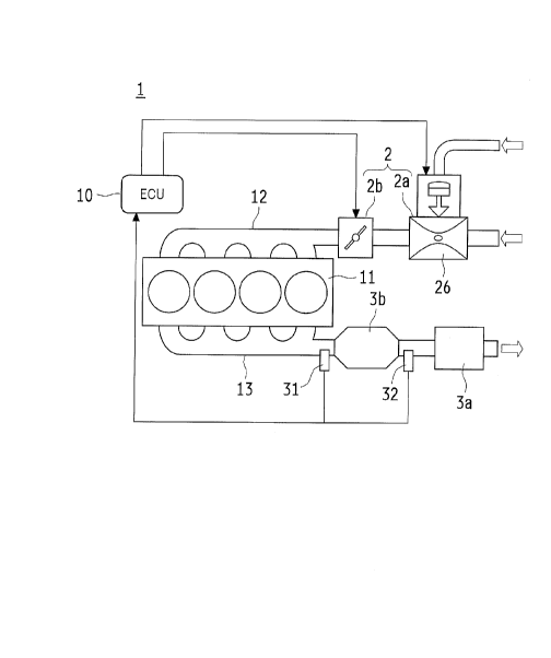
[0015] FIG. 1 schematically shows an entire configuration of a gas engine 1
according to
the present invention; FIG. 2 shows a mixing unit 2a for mixing a fuel gas and
an intake air
of the gas engine 1; FIG. 3 shows a state of a perturbation control performed
by a control
unit 10 of the gas engine 1; FIG. 4 shows a graph for explanation of a method
for calculating
an average opening degree bn; FIG. 5 shows a graph for explanation of valve
characteristics
of a solenoid valve 21 and an AN valve 22; and FIG. 6 shows a control flow of
the control
unit 10 with a change in the calorific value of a fuel gas taken into account.
[0016] The gas engine 1 includes a solenoid valve 21, an A/F valve 22, and a
control unit
for perfoaning a perturbation control by the solenoid valve 21 and the A/F
valve 22. The
10 control unit 10 being configured to: adjust an opening degree of the A/F
valve 22 such that
an average opening degree bn of the solenoid valve 21 that is calculated based
on a
predetermined number of maximal opening degrees bl and a predetermined number
of
minimal opening degrees bs achieves a target opening degree a in a case where
the average
opening degree bn is out of the target opening degree a of the solenoid valve
21 which is set
in the control unit 10 under the corresponding condition; and upon determining
that the
maximal opening degree bl or the minimal opening degree bs of the solenoid
valve 21 keeps
being an upper limit opening degree bmax or a lower limit opening degree bmin
over a
predetermined number of times, replacing the average opening degree bn with
the upper
limit opening degree bmax or the lower limit opening degree bmin, for
comparison against
.. the target opening degree a.
[0017] An entire configuration of the gas engine 1 will firstly be described.
[0018] The gas engine 1 includes: a mixing unit 2a for mixing air with a fuel
gas, the mixing
unit 2a being arranged in an intake path 12 that is connected to a cylinder
head II; and a
throttle valve 2b arranged between the mixing unit 2a and the cylinder head
11. The mixing
.. unit 2a and the throttle valve 2b constitute an intake unit 2, and the
intake unit 2 is controlled
with a signal supplied from the control unit 10.
[0019] As shown in FIG. 2, the mixing unit 2a includes a solenoid valve 21, an
A/F valve
22, a main jet 23, and an adjustment screw 24, which are connected in parallel
between a
regulator 25 and a mixer 26.
[0020] The solenoid valve 21 is formed of a flow rate characteristics valve
designed such
that its opening area in which a fuel gas passes through can be adjusted, to
control a
stoichiometric operation with an excess air ratio (X=1) that provides a
theoretical air-fuel
ratio. The solenoid valve 21 is configured such that a movable valve biased to
close a fluid
passage with a biasing force of a leaf spring, a spring, or the like, is moved
by an
electromagnetic coil and opened to a predetermined opening degree. The
solenoid valve
21 is, for example, opened and closed at a rate of 25 Hz, and its opening
degree can be
CA 02985034 2017-11-03
adjusted by changing the open-close duty cycle. The solenoid valve 21 is not
limited to 25
Hz one, but the solenoid valve 21 may be ones of various frequencies adoptable
for this type
of perturbation control. This configuration enables the solenoid valve 21 to
quickly adjust
the flow rate with a small flow rate adjustment width VI. The flow rate
characteristics
5 valve that forms the solenoid valve 21 may be a proportional control
valve.
[0021] The A/F valve 22 is formed of a proportional control valve of flow rate
characteristics designed such that the opening arca of a path in which a fuel
gas passes can
be adjusted, to control a range from the stoichiometric operation with an
excess air ratio
(k=l) that provides the theoretical air-fuel ratio to a lean operation with an
excess air ratio
(2=1.4 to 1.6) that causes lean combustion. The A/F valve 22 is configured
such that the
opening degree of a movable valve can be adjusted step-by-step by rotation of
a stepping
motor. This configuration does not enable the A/F valve 22 to quickly adjust
the flow rate,
but provides a large flow rate adjustment width V2 such that a width range of
excess air ratios
can be covered.
[0022] The main jet 23 as well as the solenoid valve 21 and the A/F valve 22
is a valve
configured to adjust the amount of fuel flowing from the regulator 25 to the
mixer 26, and
unlike the solenoid valve 21 and the A/F valve 22 described above, its opening
degree is
fixed according to the number of the main jet 23 used.
[0023] The adjustment screw 24 is a valve configured to adjust the amount of
fuel gas by
manual operation, and normally fixed together with the main jet 23 described
above.
[0024] The regulator 25 is configured to control the pressure of the fuel gas
such that the
fuel gas can be always supplied under a constant pressure.
[0025] The mixer 26 includes a venturi tube for mix air with the fuel gas. The
mixer 26
is configured to mix the fuel gas with air by the venturi effect of air sucked
in accordance
.. with the opening degree of the throttle valve 2b which is arranged on the
downstream side.
[0026] A silencer 3a is arranged in an exhaust path 13 which is connected to
the cylinder
head 11, and a three-way catalyst 3b is arranged between the silencer 3a and
the cylinder
head 11. A pre oxygen sensor 31 is arranged on the side of the three-way
catalyst 3b where
an exhaust gas enters, and another post oxygen sensor 32 is arranged on the
side where the
exhaust gas exits.
[0027] In a case of the lean operation, the mixing unit 2a perfoinis a lean
operation in the
excess air ratio range (k=1.4 to 1.6). At this time, a control of the excess
air ratio range
(k=1.4 to 1.6) is performed by the control unit 10 controlling the A/F valve
22 with the
solenoid valve 21 closed, based on a detection result obtained from an entire
region sensor
(not shown) which is arranged on the side of the three-way catalyst 3b where
the exhaust gas
enters.
CA 02985034 2017-11-03
6
=
[0028] In a case of the stoichiometric operation, the mixing unit 2a performs
a perturbation
control of the stoichiometric operation in which the air-fuel ratio varies to
the lean side and
the rich side as centered on the excess air ratio (X=1) of the theoretical air-
fuel ratio. At
this time, the perturbation control is performed by the control unit 10
controlling a variation
in the opening degree by, based on a detection result obtained from the pre
oxygen sensor
31, opening the A/F valve 22 to an opening degree in the middle of an open-
close region,
e.g., to an opening degree of 50%, and in this condition, opening the solenoid
valve 21 to an
opening degree in the middle of an open-close region, e.g., to an opening
degree of 50%,
and repeatedly opening and closing the solenoid valve 21 at a predetermined
pitch from the
opening degree of 50%.
[0029] Here, in the stoichiometric operation, the solenoid valve 21 and the
A/F valve 22
are set to opening degrees in the middle of the open-close regions because a
middle opening
degree enables a more accurate proportional control as compared to a lower
opening degree
region or a higher opening degree region. It therefore is not always necessary
to adopt the
.. middle opening degree if the accuracy of the proportional control is kept
constant over an
entire open-close region by perfoiming a correction control, etc. in a lower
opening degree
region or a higher opening degree region. In a case of the gas engine 1
performing a lean
operation, however, it is preferable that an opening degree higher than the
middle opening
degree is set for the stoichiometric operation in consideration of the fact
that the A/F valve
22 is closed at a time of a lean operation. In the following, for convenience
of illustration,
a description will be given on the assumption that the opening degree of the
solenoid valve
21 is 50% and the opening degree of the A/F valve 22 is 50% in a case where
the
stoichiometric operation is performed by using a fuel gas having a
predetermined calorific
value.
[0030] The control unit 10, in which the relationship is inputted between the
opening
degrees of the solenoid valve 21 and the A/F valve 22 in respective cases of
performing the
stoichiometric operation and the lean operation by using a fuel gas having a
predetetinined
calorific value and detection results obtained from the pre oxygen sensor 31,
the post oxygen
sensor 32, and the entire region sensor (not shown). The control unit 10 is
configured to
control the stoichiometric operation and the lean operation in accordance with
input
information.
[0031] For example, in a case of controlling the stoichiometric operation, the
control unit
10 adjusts the opening degree of the A/F valve 22 while keeping a time average
opening
degree of the solenoid valve 21 at 50% such that a measurement detection
result of the pre
oxygen sensor 31 arranged on the entrance side of the three-way catalyst 3b
can be the excess
CA 02985034 2017-11-03
7
air ratio (2=1) of the theoretical air-fuel ratio. At this time, if a
reference fuel gas is
supplied, the opening degree of the A/F valve 22 is also kept at 50%.
[0032] The perturbation control of the stoichiometric operation in which the
air-fuel ratio
varies to the lean side and the rich side as centered on the excess air ratio
(2,-1) of the
theoretical air-fuel ratio is performed by controlling the opening-closing
degree of the
solenoid valve 21 based on measurement detection results obtained from the pre
oxygen
sensor 31 arranged on the entry side of the three-way catalyst 3b and the post
oxygen sensor
32 arranged on the exit side of the three-way catalyst 3b. This perturbation
control is
performed by the control unit 10 in the following manner.
[0033] As shown in FIG. 3, the pre oxygen sensor 31 measures an oxygen
concentration
of the exhaust gas immediately before flowing into the three-way catalyst 3b.
If the pre
oxygen sensor 31 is determined to the rich side relative to the stoichiometric
operation, the
solenoid valve 21 is closed excessively to the lean side relative to the
stoichiometric
operation setting.
[0034] As a result, an excess oxygen in the exhaust gas is occluded in the
three-way catalyst
3b, and the three-way catalyst 3b is saturated with occluded oxygen, so that
the post oxygen
sensor 32 arranged subsequent to the three-way catalyst 3b shifts to the lean
side after a
predetermined response time from switching of the solenoid valve 21.
[0035] Since the solenoid valve 21 is closed to the lean side relative to the
stoichiometric
operation, the pre oxygen sensor 31 arranged prior to the three-way catalyst
3b is determined
to the lean side. In accordance with this deteimination, the solenoid valve 21
is opened
excessively to the rich side relative to the stoichiometric operation setting.
[0036] Consequently, oxygen occluded in the three-way catalyst 3b is released
to the
exhaust gas, to purify the exhaust gas. Oxygen occluded in the three-way
catalyst 3b is
depleted in due course, so that the post oxygen sensor 32 arranged subsequent
to the three-
way catalyst 3b shifts to the rich side after a predetermined response time
from switching of
the solenoid valve 21.
[0037] Thereafter, the air-fuel ratio is changed (perturbation) at a
predetermined pitch of
approximately 1 to 2 sec, so that the post oxygen sensor 32 arranged
subsequent to the three-
way catalyst 3b has a gentle change in the air-fuel ratio between the lean
side and the rich
side relative to the excess air ratio (2=1) of the theoretical air-fuel ratio.
At this time, the
three-way catalyst 3b is kept in a catalyst-activated state because oxygen is
repeatedly
occluded and released.
[0038] In the control unit 10, a control map as shown in FIG. 3 is inputted.
In a case of
performing the stoichiometric operation by using a fuel gas having a
predetermined calorific
value, the control is performed in accordance with the control map.
CA 02985034 2017-11-03
8
[0039] As shown in FIG. 4, a control parameter of the valve opening degree of
the solenoid
valve 21 is determined by a jump-up amount J by which the valve is rapidly
opened in a
predetermined time, then a rank-up speed R at which the valve is gently opened
in a
predetermined time, and then a delay time D elapsed before the solenoid valve
21 is rapidly
.. closed. Accordingly, as for the opening degree of the solenoid valve 21
which is inputted
in the control unit 10, such an opening degree change condition under the
perturbation
control is also inputted. In the stoichiometric operation, an opening degree
(herein, 50%)
of the solenoid valve 21 which corresponds to the oxygen concentration
obtained when the
pre oxygen sensor 31 has the excess air ratio (2\,=1) of the theoretical air-
fuel ratio is
recognized as the target opening degree a, and the control unit 10 is
configured to control a
variation width of the excess air ratio which varies to the lean side and the
rich side by
varying the opening degree of the solenoid valve 21 to the lean side and the
rich side relative
to the target opening degree a under the above-mentioned opening degree change
condition.
[0040] In an actual operation status in which the perturbation is performed by
the solenoid
valve 21 with predetermined engine rotation frequency and load, the control
unit 10
calculates the average opening degree bn in the actual operation status based
on a history of
the opening degree of the solenoid valve 21 within a certain time period in
which the
operation status can be considered as stable. As shown in FIG. 4, the
calculation of the
average opening degree bn is performed by measuring minimal opening degrees bs
and
maximal opening degrees bl among respective valve opening degrees under the
perturbation
control in three cycles, the minimal opening degree bs being obtained at a
time when the
lean side is switched to the rich side, the maximal opening degree bl being
obtained at a time
when the rich side is switched to the lean side. Although FIG. 4 illustrates
the case where
the calculation is made by averaging the opening degrees in three cycles, the
number of
cycles is not particularly limited to three, and the average opening degree bn
may be
calculated by averaging the opening degrees in one cycle or two cycles, or by
averaging the
opening degrees in three or more cycles. If the average opening degree bn is
calculated
based on a history of the opening degrees in one cycle previous to the actual
operation status,
a status is close to the actual operation status and data processing can be
performed quickly,
but data stability may be impaired. If the average opening degree bn is
calculated based on
a history of the opening degrees in three or more cycles previous to the
actual operation
status, stable data is obtained, but an increased amount of data needs to be
processed which
makes data processing slow. Therefore, how much previous opening degrees in
the history
from the actual operation status is used to calculate the average opening
degree bn is
determined as appropriate in accordance with the used gas engine 1 and
environments of
usage thereof
CA 02985034 2017-11-03
9
[0041] The control unit 10 compares the average opening degree bn in the
actual operation
status, which is calculated in the above-described manner, against the target
opening degree
a under the condition inputted to the control unit 10. If the average opening
degree bn is
lower than the target opening degree a, the opening degree of the A/F valve 22
is reduced to
an extent corresponding to the lowness, and if the average opening degree bn
is equal to or
higher than the target opening degree a, the opening degree of the A/F valve
22 is maintained
or opened to an extent corresponding to the highness. Thus, the control is
performed such
that the average opening degree bn coincides with the target opening degree a.
[0042] Here, in the control of making the average opening degree bn coincide
with the
target opening degree a, if the minimal opening degrees bs or the maximal
opening degrees
bl of the solenoid valve 21, which are measured for calculating the average
opening degree
bn, are continuously at a critical level, that is, continuously at the lower
limit opening degree
bmin obtained when the solenoid valve 21 is fully closed or continuously at
the upper limit
opening degree bmax obtained when the solenoid valve 21 is fully opened, the
control unit
10 determines that the perturbation control with the solenoid valve 21 is not
performed and
a variation in the calorific value of the fuel gas becomes too large,
resulting in the solenoid
valve 21 being continuously on the lower limit opening degree bmin side or the
upper limit
opening degree bmax side. Thus, the opening degree of the A/F valve 22 is
controlled until
the average opening degree bn is replaced with the lower limit opening degree
bmin or the
upper limit opening degree bmax. In this manner, a rapid change in the
calorific value of
the fuel gas which is too rapid to be controlled under the perturbation
control can be
addressed.
[0043] A control performed by the control unit 10 with a change in the
calorific value of a
fuel gas taken into account will now be described.
[0044] In a case where a fuel gas having a predetermined reference calorific
value is
supplied, the control unit 10 performs the above-described control, but in a
case where an
actually supplied fuel gas has a calorific value lower than the reference
value or in a case
where an actually supplied fuel gas has a calorific value higher than the
reference value, it
is necessary that the A/F valve 22 having a large flow rate adjustment width
V, is opened or
closed so that the A/F valve 22 is re-set to an opening degree corresponding
to the fuel gas
calorific value, as shown in FIG. 5. For example, under a state where the A/F
valve 22 is
set to an opening degree corresponding to a low calorie gas or to an opening
degree
corresponding to a high calorie gas, the flow rate adjustment width VII, V1h
of the solenoid
valve 21 is limited even though the solenoid valve 21 is set to the upper
limit opening degree
bmax corresponding to full-open or to the lower limit opening degree bmin
corresponding
CA 02985034 2017-11-03
to the full-close. It may not be possible that a range from a low calorific
value fuel gas to
a high calorific value fuel gas is controlled by the solenoid valve 21 alone.
[0045] Moreover, in a case where a calorific value of the fuel gas changes
during a control
of opening and closing the solenoid valve 21 while maintaining the opening
degree of the
5 A/F valve 22 by the control unit 10 as in the perturbation control
described above, such a
change is absorbed into the perturbation control with the solenoid valve 21,
and it is difficult
to identify whether it is caused by the perturbation control or by the change
in the calorific
value of the fuel gas. In the actual operation status, therefore, when the
calorific value of
the fuel gas changes, the solenoid valve 21 capable of quick adjustment of the
flow rate
10 follows the change, and falls under control of the solenoid valve 21. As
a result, when a
change in the air-fuel ratio occurs due to a change in the calorific value of
the fuel gas, the
perturbation is perfoltned with the solenoid valve 21 shifted in a further
opened direction or
a further closed direction. Thus, the solenoid valve 21, whose control range
is narrow,
immediately may come out of a controllable range and become uncontrollable.
[0046] Therefore, in order that the opening degree can be adjusted not by the
solenoid valve
21 but by the A/F valve 22 when a change in the calorific value of the fuel
gas occurs so that
the opening degree of the solenoid valve 21 is shifted in a further opened or
closed direction,
the control unit 10 performs a control as follows.
[0047] Firstly, a stoichiometric operation of the gas engine 1 is started with
the excess air
ratio (?.=1) of the theoretical air-fuel ratio. The stoichiometric operation
is performed by
adjusting the opening degree of the A/F valve 22 while keeping the time
average value of
the opening degree of the solenoid valve 21 at 50%. At this time, when the
fuel gas has a
predetermined calorific value, the opening degree of the A/F valve 22 is
supposed to be an
opening degree preset in the control unit 10 which means 50%, as long as the
stoichiometric
operation is performed at predetermined engine rotation frequency and load. In
an actual
operation, however, a fuel gas supplied to the gas engine 1 is not always
constant, and
depending on places, a calorific value of a fuel gas varies during a day.
[0048] In this respect, as shown in FIG. 6, to grasp a change in the calorific
value of the
fuel gas, firstly, predetermined engine rotation frequency and load are
detected during a
stoichiometric operation, and a target opening degree a of the solenoid valve
21
corresponding to such a condition, which is set in the control unit 10, is
read out (step 1).
[0049] Then, a predetermined number of minimal opening degrees bs and a
predetermined
number of maximal opening degrees bl of the current solenoid valve 21 in the
actual
operation status are read out, and whether to read out a predetermined number
of lower limit
opening degrees bmin of the solenoid valve 21 or to read out a predetermined
number of
upper limit opening degrees bmax of the solenoid valve 21 is checked (step 2).
At this
CA 02985034 2017-11-03
11
time, in a case where the perturbation control is normally performed, a
minimal opening
degree bs and a maximal opening degree bl that are within a control range of
the solenoid
valve 21 are alternately measured, but in a case where a calorific value of
the fuel gas rapidly
changes so that the perturbation control does not work, the lower limit
opening degree bmin
or the upper limit opening degree bmax of the solenoid valve 21 is
continuously measured.
[0050] If neither the lower limit opening degree bmin nor the upper limit
opening degree
bmax of the solenoid valve 21 is continuously measured, it is determined that
the
perturbation control is nolinally performed, and an average value over a
history of opening
degrees of the solenoid valve 21 within a certain time period is calculated as
the average
opening degree bn, the history of opening degrees being a history of opening
degrees of the
solenoid valve 21 from the read-out of the target opening degree a to the
actual operation
status. At this time, the minimal opening degrees bs and the maximal opening
degrees bl
of the solenoid valve 21 in the previous 10 cycles are measured and averaged,
to calculate
the average opening degree bn (step 3).
[0051] In a case where the calorific value of the fuel gas is unchanged, the
target opening
degree a read out in step 1 is coincident with the average opening degree bn
calculated in
step 2. Thus, the target opening degree a and the average opening degree bn
are compared
against each other (step 4).
[0052] If the average opening degree bn is lower than the target opening
degree a, it means
that the calorific value of the fuel gas is high by an amount corresponding to
the difference,
that is, the solenoid valve 21 is shifting in a closed direction. Thus, the
A/F valve 22 is
closed in accordance with a predetermined rate (step 5).
[0053] If the average opening degree bn is higher than the target opening
degree a, it means
that the calorific value of the fuel gas is low by an amount corresponding to
the difference,
that is, the solenoid valve 21 is shifting in an opened direction. Thus, the
A/F valve 22 is
opened in accordance with a predetelinined rate. If the average opening degree
bn is equal
to the target opening degree a, it means that the calorific value of the fuel
gas is unchanged,
that is, the solenoid valve 21 is not shifting. Thus, the opening degree of
the A/F valve 22
is kept at the current rate (step 6).
[0054] If either the lower limit opening degree bmin or the upper limit
opening degree
bmax of the solenoid valve 21 is continuously measured, it is determined that
a rapid change
in the calorific value that makes the calorific value of the fuel gas out of
the perturbation
control is occurring, and the subsequent control is performed by using not the
average
opening degree bn but either the lower limit opening degree bmin or the upper
limit opening
degree bmax that has been continuously measured (step 7).
CA 02985034 2017-11-03
12
[0055] Firstly, the average opening degree bn is replaced with the lower limit
opening
degree bmin or the upper limit opening degree bmax that has been continuously
measured,
and compared against the target opening degree a read out in step 1 (step 4).
[0056] In a case where the lower limit opening degree bmin replaces, that is,
the lower limit
opening degree bmin has been continuously measured, it means that the
calorific value of
the fuel gas rapidly increases to be out of the perturbation control by an
amount
corresponding to the lowness relative to the target opening degree a. Thus,
the A/F valve
22 is closed in accordance with a predetermined rate (step 5).
[0057] In a case where the upper limit opening degree bmax replaces, that is,
the upper
limit opening degree bmax has been continuously measured, it means that the
calorific value
of the fuel gas rapidly decreases to be out of the perturbation control by an
amount
corresponding to the highness relative to the target opening degree a. Thus,
the A/F valve
22 is opened in accordance with a predetermined rate (step 6).
[0058] Thereafter, the control is repeated from step 1.
[0059] Accordingly, when a fuel gas having a calorific value lower or higher
than the
reference fuel gas is supplied, the gas engine 1 can address it by adjusting
the opening degree
of the A/F valve 22 instead of the solenoid valve 21. Thus, even when the
calorific value
of the fuel gas largely changes, the change can be addressed, and the
perturbation control of
the stoichiometric operation with the solenoid valve 21 can be continuously
performed.
Therefore, exhaust gas purification performance can be maintained for a
prolonged time, so
that the maintenance interval can be prolonged. In addition, it is not
necessary to increase
the amount of noble metal in the catalyst or the volume thereof, which can
prevent an
increase in the costs of catalyst. Moreover, the gas engine 1 can be operated
even with use
of a fuel gas whose calorific value largely changes. Furthermore, the gas
engine 1 can be
used in a plurality of countries and regions where fuel gases have different
calorific values.
[0060] Even in a situation where the calorific value of the fuel gas rapidly
increases or
decreases to be out of the perturbation control, a state where the
perturbation control is
enabled can be restored by replacing the average opening degree bn with the
lower limit
opening degree bmin or the upper limit opening degree bmax and adjusting the
opening
degree of the A/F valve 22.
[0061] As shown in FIG. 5, a gas flow rate adjustment width V1 obtained when
the solenoid
valve 21 is changed from full-close to full-open with a low calorie gas
supplied is largely
different from a gas flow rate adjustment width Vh obtained when the solenoid
valve 21 is
changed from full-close to full-open with a high calorie gas supplied.
Performing the
perturbation control while changing the opening degree by the same amount,
therefore,
makes a variation in the air-fuel ratio unsuccessful. Accordingly, in
performing the
CA 02985034 2017-11-03
13
perturbation control of the stoichiometric operation with the solenoid valve
21, it is
preferable that when the opening degree of the A/F valve 22 is re-set for a
low calorie gas,
the opening-closing degree of the solenoid valve 21 has an amount of change in
the opening
degree with the flow rate adjustment width VI taken into account, while when
the opening
degree of the A/F valve 22 is re-set for a high calorie gas, the opening-
closing degree of the
solenoid valve 21 has an amount of change in the opening degree with the flow
rate
adjustment width Vh taken into account. In this case, the amount of change in
the opening
degree of the solenoid valve 21 with the flow rate adjustment width V1, Vh
taken into account
can be inputted and set in the control unit 10 in association with the opening
degree of the
A/F valve 22.
[0062] In the embodiment above-described, the target opening degree a is
compared
against the average opening degree bn. and by an amount corresponding to the
difference,
the A/F valve 22 is controlled in accordance with the predetermined rate. It
however is
difficult that the target opening degree a and the average opening degree bn
are completely
coincident with each other. In the above-described control, therefore,
frequent opening and
closing of the A/F valve 22 are repeated, which may undesirably increase a
burden on the
control unit 10. Thus, it may be acceptable that not only each of target
opening degrees a
mapped in the control unit 10 but also a dead zone width c which corresponds
to the target
opening degree a is inputted and set in the control unit 10 so that the
control may be
performed by using the dead zone width c.
[0063] The dead zone width c is a value that is set in order to prevent the
A/F valve 22
from being frequently opened and closed in response to a difference between
the target
opening degree a and the average opening degree bn, and is a numerical value
range that is
set such that the opening degree of the A/F valve 22 is not changed unless the
difference
exceeds this value. The dead zone width c, therefore, is appropriately set in
accordance
with the used gas engine 1 and environments of usage thereof.
[0064] FIG. 7 shows a case where the air-fuel ratio of the engine is
controlled by using the
dead zone width c provided in the control unit 10.
[0065] Similarly to step I shown in FIG. 6, predetermined engine rotation
frequency and
load are detected during a stoichiometric operation, and a target opening
degree a of the
solenoid valve 21 corresponding to such a condition, which is set in the
control unit 10, is
read out (step 11).
[0066] Then, a predetermined number of opening degrees of the current solenoid
valve 21
in the actual operation status are read out (step 12).
[0067] If neither the lower limit opening degree bmin nor the upper limit
opening degree
bmax of the solenoid valve 21 is continuously measured, it is determined that
the
CA 02985034 2017-11-03
14
perturbation control is normally performed, and an average value over a
history of opening
degrees of the solenoid valve 21 within a certain time period is calculated as
the average
opening degree bn, the history of opening degrees being a history of opening
degrees of the
solenoid valve 21 from the read-out of the target opening degree a to the
actual operation
status. At this time, the minimal opening degrees bs and the maximal opening
degrees bl
of the solenoid valve 21 in the previous 10 cycles are measured and averaged,
to calculate
the average opening degree bn (step 13).
[0068] The dead zone width e within a period in which the engine rotation
frequency and
load are constant, which is the same as when the target opening degree a is
read out, is read
out from the control unit 10 (step 14).
[0069] When a change in the calorific value of the fuel gas is small, a
difference between
the target opening degree a read out in step 11 and the average opening degree
bn calculated
in step 13 is supposed to be smaller than the dead zone width c. Thus, a
difference (a¨bn)
between the target opening degree a and the average opening degree bn is
compared against
the dead zone width c (step 15).
[0070] If the difference (a¨bn) between the target opening degree a and the
average
opening degree bn is equal to or smaller than the dead zone width c, a change
in the calorific
value of the fuel gas is within an allowable range, and therefore the control
from step 11 is
repeated.
[0071] If the difference (a¨bn) between the target opening degree a and the
average
opening degree bn is greater than the dead zone width c, a change in the
calorific value of
the fuel gas is beyond the allowable range, and therefore the target opening
degree a and the
average opening degree bn are compared against each other (step 16).
[0072] If the average opening degree bn is lower than the target opening
degree a, it means
that the calorific value of the fuel gas is high by an amount corresponding to
the difference,
that is, the solenoid valve 21 is shifting in a closed direction. Thus, the
A/1- valve 22 is
closed in accordance with a predetermined rate (step 17).
[0073] If the average opening degree bn is higher than the target opening
degree a, it means
that the calorific value of the fuel gas is low by an amount corresponding to
the difference,
that is, the solenoid valve 21 is shifting in an opened direction. Thus, the
A/F valve 22 is
opened in accordance with a predetermined rate. If the average opening degree
bn is equal
to the target opening degree a, it means that the calorific value of the fuel
gas is unchanged,
that is, the solenoid valve 21 is not shifting. Thus, the opening degree of
the A/F valve 22
is kept at the current rate (step 18).
[0074] If the lower limit opening degree bmin or the upper limit opening
degree bmax of
the solenoid valve 21 is continuously measured, it is determined that a rapid
change in the
CA 02985034 2017-11-03
calorific value that makes the calorific value of the fuel gas out of the
perturbation control is
occurring, and the subsequent control is performed by using not the average
opening degree
bn but the lower limit opening degree bmin or the upper limit opening degree
bmax (step
19).
5 [0075] Firstly, the average opening degree bn is replaced with the lower
limit opening
degree bmin or the upper limit opening degree bmax that has been continuously
measured,
and compared against the target opening degree a read out in step 11 (step
16). At this time,
a difference of the lower limit opening degree bmin or the upper limit opening
degree bmax
from the target opening degree a, which different is caused by replacing the
average opening
10 degree bn with the lower limit opening degree bmin or the upper limit
opening degree bmax,
is considerably greater than the dead zone width c, and therefore any control
delay due to
the dead zone width c is not caused. Therefore, although the control can be
performed
through step 15, it is preferable to skip step 15 and go step 16 as shown in
FIG. 7 for the
purpose of reducing, even a little of, the burden involved in information
processing.
15 [0076] In a case where the lower limit opening degree bmin replaces,
that is, the lower limit
opening degree bmin has been continuously measured, it means that the
calorific value of
the fuel gas rapidly increases to be out of the perturbation control by an
amount
corresponding to the lowness relative to the target opening degree a. Thus,
the A/F valve
22 is closed in accordance with a predetermined rate (step 17).
[0077] In a case where the upper limit opening degree bmax replaces, that is,
the upper
limit opening degree bmax has been continuously measured, it means that the
calorific value
of the fuel gas rapidly decreases to be out of the perturbation control by an
amount
corresponding to the highness relative to the target opening degree a. Thus,
the A/F valve
22 is opened in accordance with a predetermined rate (step 18).
[0078] Thereafter, the control is repeated from step I I .
[0079] Accordingly, when a fuel gas having a calorific value lower or higher
than the
reference fuel gas is supplied, the gas engine 1 can address it by adjusting
the opening degree
of the A/F valve 22 instead of the solenoid valve 21. Thus, even when the
calorific value
of the fuel gas largely changes, the change can be addressed, and the
perturbation control of
the stoichiometric operation with the solenoid valve 21 can be continuously
performed.
[0080] In addition, controlling with use of the dead zone width c can prevent
the A/F valve
22 from being frequently opened and closed in response to a difference between
the target
opening degree a and the average opening degree bn, and also can reduce a
burden involved
in information processing performed by the control unit 10. Thus, for example,
accidental
occurrence of hunting of the air-fuel ratio can be prevented, and the air-fuel
ratio control can
be stabilized.
CA 02985034 2017-11-03
16
[0081] Even though the control is performed with use of the dead zone width c;
if the
calorific value of the fuel gas rapidly increases or decreased to be out of
the perturbation
control, the opening degree of the A/F valve 22 can be quickly adjusted to
restore a state
where the perturbation control is enabled, without the control being slowed in
response to
the dead zone width c.
[0082] In this embodiment, one mixing unit 2a is provided in the intake path
12, but one
mixing unit 2a may be provided in each cylinder head 11 of the gas engine 1 as
shown in
FIG. 8(a), or one mixing unit 2a may be provided in every two or more (in the
drawing, two)
cylinder heads 11 as shown in FIG. 8(b).
[0083] In this embodiment, the mixing unit 2a is configured to control the
solenoid valve
21 and the A/F valve 22 having different flow rate characteristics, it may be
acceptable that
two, three, or more (in drawing, three) fuel flow rate adjustment valves 20
having the same
flow rate characteristics are provided and the mixing unit 2a is configured to
control them
as shown in FIG. 9. In such a configuration, a fuel flow rate adjustment valve
20 that works
similarly to the solenoid valve 21 of this embodiment and a fuel flow rate
adjustment valve
that works similarly to the A/F valve 22 may be provided; or alternatively
each of the fuel
flow rate adjustment valves 20 may be configured to work similarly to the
solenoid valve 21
of this embodiment and the A/F valve 22 may be configured to work similarly.
In this case,
various valves usable for this type of fuel gas control, as typified by
butterfly valves and
20 solenoid valves, are adoptable as the fuel flow rate adjustment valve
20.
[0084] In the above-described configuration, the gas engine 1 is able to
switch between the
stoichiometric operation and the lean operation, but the gas engine 1 may be
configured to
perform only the stoichiometric operation. Although the gas engine 1 is
configured such
that the excess air ratio in the stoichiometric operation is detected by the
pre oxygen sensor
31, it may be acceptable to use an entire region sensor (not shown) instead of
the pre oxygen
sensor 31 to detect the excess air ratio in the stoichiometric operation.
[0085] Each of the above-described gas engines 1 having such a configuration
can be
suitably used as a drive source of a gas heat pump apparatus (not shown). The
gas engine
1 can also be suitably used as a drive source of a cogeneration apparatus (not
shown).
[0086] Although this embodiment describes the gas engine 1, it may be
applicable not only
to the gas engine 1 but also to various engines in which a perturbation
control is performed.
[0087] It should be noted that the present invention may be embodied in many
different
forms without departing from the spirit or essential characteristics thereof
The above-
described embodiments are therefore to be considered in all respects only as
illustrative and
not restrictive. The scope of the present invention is defined by the claims,
and never
' 84108558
17
bound by the description. All modifications and changes which come within the
scope of the
claims are to be embraced by the present invention.
Reference Signs List
[0088] 1 gas engine
control unit (control means)
13 exhaust path
2 intake unit
21 solenoid valve (first valve)
10 22 A/F valve (second valve)
3b three-way catalyst (exhaust gas purification catalyst)
31 pre oxygen sensor (air-fuel ratio detection sensor)
32 post oxygen sensor
a target opening degree
bn average opening degree
bs minimal opening degree
bl maximal opening degree
bmax upper limit opening degree
bmin lower limit opening degree
CA 2985034 2017-11-14