Note: Descriptions are shown in the official language in which they were submitted.
CA 02985035 2017-11-03
DESCRIPTION
Title of Invention: PROFILED BELT AND METHOD FOR MANUFACTURING
SAME
Technical Field
[0001]
The present invention relates to a profiled belt that includes a belt body and
a
profile provided on a back surface of the belt body, and a manufacturing
method of the
same belt.
Background Art
[0002]
It has been known that a convex profile is provided on a back surface of a
belt
body of a toothed belt, a flat belt or the like, so that conveyance,
arrangement, sorting,
etc. of articles can be performed by profile. In addition, as a method for
providing the
profile on the back surface of the belt body, there have been known some
methods,
including a method for welding/fusing the profile to the back surface of the
belt body
(see Patent Literature 1), a method in which a deleted portion (hole) is
provided in the
belt body, and a connection portion is charged into the deleted portion or a
lock pin is
provided in the deleted portion (see Patent Literature 2), a method in which
the belt
body and the profile are molded integrally (see Patent Literature 3), a method
in which
the profile is outsert-molded on a support protrusion portion provided on the
back
surface of the belt body (see Patent Literature 4), etc.
Citation List
Patent Literature
[0003]
Patent Literature 1: JP-UM-A-5-64114
Patent Literature 2: JP-A-2003-63630
Patent Literature 3: JP-A-2001-122415
Patent Literature 4: JP-A-2005-114175
1
CA 02985035 2017-11-03
Summary of Invention
Problem that the Invention is to solve
[0004]
In the method according to Patent Literature 1, selection of a material of the
profile is restricted, and the profile cannot be replaced. In the method
according to
Patent Literature 2, strength of the belt body is reduced by the hole provided
in the belt
body. Particularly when a tension member embedded in the belt body is cut due
to the
formation of the hole, the strength of the belt body can be reduced on a large
scale. In
the methods according to the Patent Literatures 3 and 4, it is necessary to
prepare a
mold for molding the belt body and the profile. It is therefore difficult to
reduce the
manufacturing cost, and it is also difficult to cope with a change in shape or
size of the
belt body or the profile.
[0005]
An object of the present invention is to provide a profiled belt and a
manufacturing method thereof, in which selection of a material of a profile is
not
restricted excessively, the profile can be replaced, while reduction in
strength of a belt
body can be suppressed, and it is easy to reduce the manufacturing cost and
cope with a
change in shape or size of the belt body or the profile.
Means for solving the Problem
[0006]
According to a first aspect of the present invention, there is provided a
profiled
belt including a belt body, a profile that is provided on a back surface of
the belt body,
and a fixation member that detachably fixes the profile to the belt body,
wherein the belt
body includes a protrusion on the back surface, the profile includes a recess
portion to
which the protrusion is fitted, the fixation member fixes the profile to the
belt body in a
state where the protrusion has been fitted to the recess portion, and the
fixation member
is removably inserted to the profile and the protrusion.
[0007]
According to a second aspect of the present invention, there is provided a
method for manufacturing a profiled belt including a belt body, a profile that
is provided
2
CA 02985035 2017-11-03
on a back surface of the belt body, and a fixation member that detachably
fixes the
profile to the belt body, the method comprising a belt body production step of
producing
the belt body including a protrusion on the back surface, a profile production
step of
producing the profile including a recess portion to which the protrusion is
fitted, and a
fixation step of fixing the profile to the belt body by use of the fixation
member in a
state where the protrusion has been fitted to the recess portion, wherein in
the fixation
step, the fixation member is removably inserted to the profile and the
protrusion so that
the profile is detachably fixed to the belt body by the fixation member.
[0008]
According to the aforementioned first and second aspects, which have not a
configuration in which a profile is welded/fused but a configuration in which
a profile is
detachably fixed to a belt body by a fixation member, selection of a material
of the
profile is not restricted excessively, and the profile can be replaced (for
example, a
profile reaching the end of its lifetime can be replaced by a new one). In
addition, it is
not necessary to provide a hole in the belt body. Therefore, reduction in
strength of
the belt body is suppressed. Further, an expensive mold is not required. It is
therefore easy to reduce the manufacturing cost and deal with a change in
shape or size
of the belt body or the profile.
[0009]
The protrusion may be provided on the back surface by integral molding.
[0010]
According to the aforementioned configuration, the protrusion is hardly
detached from the belt body, as compared with such a case that the protrusion
is bonded
to the belt body. Thus, the profile can be more surely fixed to the belt body
through
the protrusion.
[0011]
The fixation member may include an extension portion that extends in a
parallel direction parallel to the back surface and that penetrates the
profile and the
protrusion.
[0012]
According to the aforementioned configuration, the profile can be more surely
fixed to the belt body by use of the fixation member.
3
CA 02985035 2017-11-03
[0013]
The fixation member may include a plurality of the extension portions, and a
connection portion that connects one ends of the plurality of the extension
portions in
the parallel direction.
[0014]
According to the aforementioned configuration, the extension portions are
provided so that the profile can be more surely fixed to the belt body. In
addition, the
connection portion is provided so that the fixation member can be prevented
from
moving in a direction from the one end toward the other end of the extension
portions.
It is therefore possible to more surely prevent the fixation member from
coming off, and
hence it is possible to more surely fix the profile to the belt body.
[0015]
The profile may include a connection portion receiving portion that receives
the connection portion.
[00161
According to the aforementioned configuration, contact between the fixation
member and another component is suppressed. It is therefore possible to more
surely
prevent the fixation member from coming off, and hence it is possible to more
surely fix
the profile to the belt body.
[0017]
The protrusion may be longer in one direction of a longitudinal direction and
a
width direction of the belt body than in the other direction, and the parallel
direction
may be the one direction.
[0018]
According to the aforementioned configuration, the extension portion is
extended in a longitudinal direction of the protrusion so that the holding
force of the
profile to the protrusion can be improved, as compared with a case where the
extension
portion is extended in a lateral direction of the protrusion.
[0019]
The fixation member may further include an expansion portion that is provided
in an end portion of the extension portion in the parallel direction, the end
portion being
not connected to another element, and that has a size in a perpendicular
direction
4
CA 02985035 2017-11-03
perpendicular to the parallel direction being larger at least in a part to be
connected to
the end portion than a size of the end portion in the perpendicular direction.
[0020]
According to the aforementioned configuration, it is possible to more surely
prevent the fixation member from coming off, and hence it is possible to more
surely fix
the profile to the belt body.
[0021]
The profile may include an expansion portion receiving portion that receives
the expansion portion.
[0022]
According to the aforementioned configuration, contact between the fixation
member and another component is suppressed. It is therefore possible to more
surely
prevent the fixation member from coming off, and hence it is possible to more
surely fix
the profile to the belt body.
[0023]
The expansion portion may have a size in the perpendicular direction being
reduced as going in the parallel direction away from the end portion of the
extension
portion, and the size in the perpendicular direction of the expansion portion
at the
furthest end in the parallel direction from the end portion of the extension
portion is
equal to the size of the extension portion in the perpendicular direction or
smaller than
the size.
[0024]
According to the aforementioned configuration, it is possible to easily
perform
work of inserting the fixation member into the profile and the protrusion from
the end of
the expansion portion, and hence it is possible to easily perform work of
attaching the
profile to the belt body.
[0025]
The fixation member may be made of metal.
[0026]
According to the aforementioned configuration, the fixation member can be
deformed comparatively easily. It is therefore possible to form the extension
portion
easily.
CA 02985035 2017-11-03
5=
[0027]
It is preferable that the fixation member does not protrude from an external
surface of the profile.
[0028]
According to the aforementioned configuration, contact between the fixation
member and another component is suppressed. It is therefore possible to more
surely
prevent the fixation member from coming off, and hence it is possible to more
surely fix
the profile to the belt body.
Advantage of the Invention
[0029]
The present invention provides not a configuration in which a profile is
welded/fused but a configuration in which a profile is detachably fixed to a
belt body by
a fixation member. Accordingly, selection of a material of the profile is not
restricted
excessively, but the profile can be replaced (for example, a profile reaching
the end of
its lifetime can be replaced by a new one). In addition, it is not necessary
to provide a
hole in the belt body. Therefore, reduction in strength of the belt body is
suppressed.
Further, an expensive mold is not required. It is therefore easy to reduce the
manufacturing cost and deal with a change in shape or size of the belt body or
the
profile.
Brief Description of the Drawings
[0030]
FIG. l is a schematic view showing a state in which a profiled belt according
to
a first embodiment of the present invention has been wound around a driving
pulley and
a driven pulley.
FIG. 2 is a partially perspective view showing the profiled belt according to
the
first embodiment of the present invention.
FIG. 3 is a partially perspective view showing a profiled belt according to a
second embodiment of the present invention.
FIG. 4 is a partially perspective view showing a profiled belt according to a
third embodiment of the present invention.
6
CA 02985035 2017-11-03
= =
FIG. 5 is a partially perspective view showing a profiled belt according to a
fourth embodiment of the present invention.
FIG. 6 is a partially perspective view showing an example of a step of forming
extension portions in the profiled belt according to the fourth embodiment of
the present
invention.
FIG. 7 is a partially perspective view showing a profiled belt according to a
fifth embodiment of the present invention.
The part (a) of FIG. 8 is a partially sectional perspective view taken along
line
VIIIA to VIIIA in FIG. 7, showing a profiled belt according to a sixth
embodiment of
the present invention, and the part (b) of FIG. 8 is an enlarged view of a
part VIIIB
shown in the part (a) of FIG. 8.
FIG. 9 is a flow chart showing an embodiment of a method for manufacturing a
profiled belt according to the present invention.
Mode for Carrying Out the Invention
[0031]
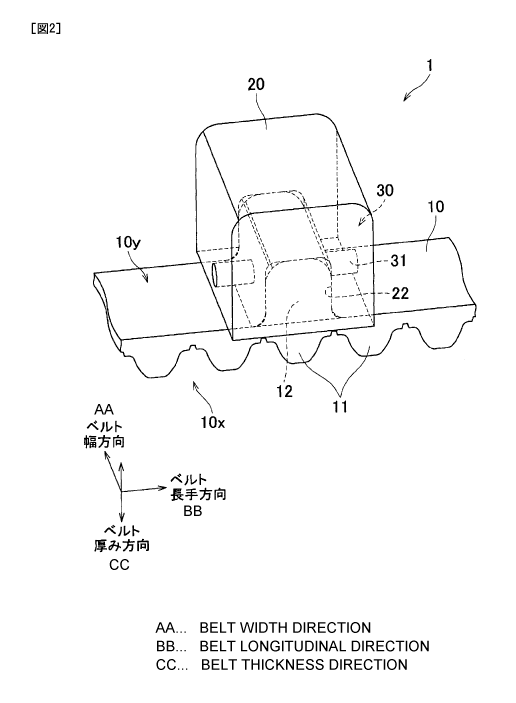
A profiled belt 1 according to a first embodiment of the present invention
includes an endless (annular) belt body 10, and a plurality of profiles 20
provided on a
back surface lOy of the belt body 10. The profiles 20 are provided at
predetermined
intervals in a longitudinal direction of the belt body 10 (hereinafter
referred to as ''belt
longitudinal direction"). The profiled belt I is, for example, wound around a
driving
pulley 51 and a driven pulley 52 so that the profiled belt 1 can run in
accordance with
the rotation of the driving pulley 51 and the driven pulley 52.
[0032]
The belt body 10 is made of an elastic material (such as elastomer of
polyurethane), and formed by cast molding or the like. The belt body 10 is a
toothed
belt, in which a plurality of teeth 11 are provided in an inner surface 10x.
The teeth 11
extend in a width direction of the belt body 10 (hereinafter referred to as
"belt width
direction"), and arranged at predetermined intervals in the belt longitudinal
direction so
as to be spaced from one another. In addition, the belt body 10 includes a
tension
member (not shown) extending in the belt longitudinal direction.
[0033]
7
CA 02985035 2017-11-03
The belt body 10 has a plurality of protrusions 12 (see FIG. 2) on the back
surface 10y. The protrusions 12 are provided to correspond to each of profiles
20 one
by one. The protrusions 12 are arranged at predetermined intervals in the belt
longitudinal direction so as to be spaced from one another. The protrusions 12
are
provided on the back surface lOy by integral molding. The protrusion 12 has a
length
equal to the belt body 10 in the belt width direction.
[0034]
The profile 20 is made of resin (such as ABS resin), and includes a recess
portion 22 to which the protrusion 12 is fitted. The recess portion 22 is open
to a
bottom surface (which is a surface facing the back surface 10y) of the profile
20. The
profile 20 may be, for example, formed by injection molding, or may be formed
in such
a manner that a profile precursor having no recess portion 22 is formed and
the recess
portion 22 is then formed in the precursor by cutting.
[0035]
A through hole that a fixation member 30 penetrates is formed in advance in
each of the profile 20 and the protrusion 12. The through hole penetrates the
profile 20
and the protrusion 12 in the belt longitudinal direction and at their centers
in the belt
width direction respectively.
[0036]
The fixation member 30 is a rod-like member made of metal (such as iron or
aluminum). The fixation member 30 includes an extension portion 31 extending
in a
parallel direction (corresponding to the belt longitudinal direction in the
embodiment)
parallel to the back surface lOy and penetrating the profile 20 and the
protrusion 12.
The extension portion 31 is a columnar member having a constant diameter and
penetrates the through hole formed in advance in the profile 20 and the
protrusion 12.
The fixation member 30 does not protrude from an external surface of the
profile 20.
[0037]
The fixation member 30 serves to fix the profile 20 to the belt body 10 in a
state where the protrusion 21 has been fitted to the recess portion 22. The
fixation
member 30 is removably inserted to the profile 20 and the protrusion 12. By
the
fixation member 30, the profile 20 is detachably fixed to the belt body 10.
[0038]
8
CA 02985035 2017-11-03
In order to attach the profile 20 to the belt body 10, first, the profile 20
is
moved relatively to the belt body 10 in a direction from the back surface lOy
toward the
inner surface 10x so that the protrusion 12 can be fitted to the recess
portion 22. The
profile 20 is disposed thus on the back surface 10y. After that, the fixation
member 30
is inserted in the belt longitudinal direction from a lateral side of the
profile 20 so as to
penetrate the profile 20 and the protrusion 12. As a result, the profile 20 is
fixed to the
belt body 10.
[0039]
In order to remove the profile 20 from the belt body 10, first, the fixation
member 30 is moved relatively to the profile 20 in the belt longitudinal
direction.
Thus, the fixation member 30 is extracted to the outside of the profile 20.
After that,
the profile 20 is moved relatively to the belt body 10 in a direction from the
inner
surface 10x toward the back surface lOy so that the profile 20 is separated
from the belt
body 10. As a result, the profile 20 is removed from the belt body 10.
[0040]
As described above, the embodiment provides not a configuration in which the
profile 20 is welded/fused but a configuration in which the profile 20 is
detachably
fixed to the belt body 10 by the fixation member 30. Accordingly, selection of
a
material of the profile 20 is not restricted excessively, but the profile 20
can be replaced
(for example, the profile 20 reaching the end of its lifetime can be replaced
by a new
one). In addition, it is not necessary to provide a hole in the belt body 10.
Therefore,
reduction in strength of the belt body 10 is suppressed. Further, an expensive
mold is
not required. It is therefore easy to reduce the manufacturing cost and deal
with a
change in shape or size of the belt body 10 or the profile 20.
[0041]
The protrusion 12 is provided on the back surface lOy by integral molding.
[0042]
According to the aforementioned configuration, the protrusion 12 is hardly
detached from the belt body 10, as compared with such a case that the
protrusion 12 is
bonded to the belt body 10. Thus, the profile 20 can be more surely fixed to
the belt
body 10 through the protrusion 12.
[0043]
9
CA 02985035 2017-11-03
The fixation member 30 includes an extension portion 31 extending in a
parallel direction (corresponding to the belt longitudinal direction in the
embodiment)
parallel to the back surface by and penetrating the profile 20 and the
protrusion 12.
[0044]
According to the aforementioned configuration, it is possible to more surely
fix
the profile 20 to the belt body 10 by use of the fixation member 30.
[0045]
The fixation member 30 does not protrude from the external surface of the
profile 20.
[0046]
According to the aforementioned configuration, contact between the fixation
member 30 and another component is suppressed. It is therefore possible to
more
surely prevent the fixation member 30 from coming off, and hence it is
possible to more
surely fix the profile 20 to the belt body 10.
[0047]
Next, a profiled belt 201 according to a second embodiment of the present
invention will be described with reference to FIG. 3. Constituent elements the
same as
those in the first embodiment will be referenced correspondingly, and their
description
will be omitted accordingly.
[0048]
The profiled belt 201 includes a belt body 10, a plurality of profiles 220
provided on a back surface by of the belt body 10, and a fixation member 230
for
detachably fixing the profile 220 to the belt body 10.
[0049]
The fixation member 230 is a U-shaped member made of metal (such as iron or
aluminum). The fixation member 230 includes two extension portions 31, and a
connection portion 32 that connects one ends of the two extension portions 31
in the
parallel direction (corresponding to the belt longitudinal direction in the
embodiment).
The connection portion 32 extends in a direction (corresponding to the belt
width
direction in the embodiment) parallel with the back surface lOy and
perpendicular to the
parallel direction.
[0050]
CA 02985035 2017-11-03
The profile 220 has, in addition to a recess portion 22, a connection portion
receiving portion 222 that receives the connection portion 32. The connection
portion
receiving portion 222 is open to one side surface (one side surface extending
in the belt
width direction) of the profile 220 in the belt longitudinal direction.
[0051]
The fixation member 230 does not protrude from an external surface of the
profile 220, in the same manner as in the first embodiment.
[0052]
In order to attach the profile 220 to the belt body 10, first, the profile 220
is
moved relatively to the belt body 10 in a direction from the back surface by
toward the
inner surface 10x so that the protrusion 12 can be fitted to the recess
portion 22, in the
same manner as in the first embodiment. The profile 220 is disposed thus on
the back
surface by. After that, the fixation member 230 is moved relatively to the
profile 220
in a direction from an one end side (end portions where the connection portion
32 is
provided) of the two extension portions 31 toward the other end side in the
belt
longitudinal direction, and inserted in the belt longitudinal direction from a
lateral side
(a lateral side where the connection portion receiving portion 222 is open) of
the profile
220 so as to penetrate the profile 220 and the protrusion 12. As a result, the
profile
220 is fixed to the belt body 10.
[0053]
In order to remove the profile 220 from the belt body 10, first, the fixation
member 230 is moved relatively to the profile 220 in a direction from the
other end side
of the two extension portions 31 toward the one end side (the end portions
where the
connection portion 32 is provided) in the belt longitudinal direction. Thus,
the fixation
member 230 is extracted to the outside of the profile 220. After that, the
profile 220 is
moved relatively to the belt body 10 in a direction from the inner surface 10x
toward the
back surface by so that the profile 220 is separated from the belt body 10. As
a
result, the profile 220 is removed from the belt body 10.
[0054]
As described above, according to the embodiment, the following effects can be
obtained as well as similar effects to those of the first embodiment based on
the similar
configuration to that of the first embodiment.
11
CA 02985035 2017-11-03
[0055]
The fixation member 230 includes the two extension portions 31, and the
connection portion 32 that connects one ends of the two extension portions 31
in the
parallel direction (corresponding to the belt longitudinal direction in the
embodiment).
[0056]
According to the aforementioned configuration, the two extension portions 31
are provided so that the profile 220 can be more surely fixed to the belt body
10. In
addition, since the connection portion 32 is provided, the fixation member 230
can be
prevented from moving in a direction from the one end side (end portions where
the
connection portion 32 is provided) toward the other end side of the extension
portions
31 in the parallel direction (corresponding to the belt longitudinal direction
in the
embodiment). Thus, it is possible to more surely prevent the fixation member
230
from coming off, and hence it is possible to more surely fix the profile 220
to the belt
body 10.
[0057]
The profile 220 includes the connection portion receiving portion 222 for
receiving the connection portion 32.
[0058]
According to the aforementioned configuration, contact between the fixation
member 230 and another component is suppressed. It is therefore possible to
more
surely prevent the fixation member 230 from coming off, and hence it is
possible to
more surely fix the profile 220 to the belt body 10.
[0059]
Next, a profiled belt 301 according to a third embodiment of the present
invention will be described with reference to FIG. 4. Constituent elements the
same as
those in the first embodiment will be referenced correspondingly, and their
description
will be omitted accordingly.
[0060]
The profiled belt 301 includes a belt body 10, a plurality of profiles 320
provided on a back surface lOy of the belt body 10, and a fixation member 330
for
detachably fixing the profile 320 to the belt body 10.
[0061]
12
f CA 02985035 2017-11-03
The fixation member 330 is a rod-like member made of metal (such as iron or
aluminum) in the same manner as in the first embodiment. The fixation member
330
includes one extension portion 31.
[0062]
The fixation member 330 further includes expansion portions 33 provided on
both ends of the extension portion 31 in the parallel direction (corresponding
to the belt
longitudinal direction in the embodiment). The both ends of the extension
portion 31
are not connected to any other elements.
[0063]
Each expansion portion 33 has a size in a perpendicular direction
(corresponding to the belt width direction and/or the belt thickness direction
in the
embodiment) perpendicular to the parallel direction being larger at least in a
part to be
connected to the end portion (one end or the other end of the extension
portion 31 in the
belt longitudinal direction). The expansion portion 33 provided at one end
(left side in
FIG. 4) of the extension portion 31 in the belt longitudinal direction has a
columnar
shape having a larger diameter than a diameter of the extension portion 31.
The
expansion portion 33 provided at the other end (right side in FIG. 4) of the
extension
portion 31 in the belt longitudinal direction has a shape bent in the belt
width direction
from the other end of the extension portion 31.
[0064]
The profile 320 has, in addition to a recess portion 22, expansion portion
receiving portions 323 that receive each expansion portion 33. The expansion
portion
receiving portions 323 are open to both side surfaces (two side surfaces
extending in the
belt width direction) of the profile 320 in the belt longitudinal direction.
[0065]
The fixation member 330 does not protrude from an external surface of the
profile 220, in the same manner as in the first embodiment.
[0066]
The fixation member 330 may be manufactured as follows. A member having
no expansion portion 33 as in the fixation member 30 according to the first
embodiment
is used as a fixation member precursor, and the precursor is made to penetrate
the
profile 320 and the protrusion 12. After that, the expansion portions 33 are
formed at
13
CA 02985035 2017-11-03
both ends of the extension portion 31 of the precursor in the belt
longitudinal direction
by a desired method (for example, by use of a pair of pressing jigs 500 shown
in FIG.
6). Alternatively, the fixation member 330 may be produced as follows. A
member
provided with only one expansion portion 33 in the fixation member 30
according to the
first embodiment is used as a fixation member precursor, and the precursor is
made to
penetrate the profile 320 and the protrusion 12. After that, the other
expansion portion
33 is formed at an end of the extension portion 31 of the precursor where the
expansion
portion 33 has not been provided yet, by a desired method.
[0067]
In order to attach the profile 320 to the belt body 10, first, the profile 320
is
moved relatively to the belt body 10 in a direction from the back surface lOy
toward the
inner surface 10x so that the protrusion 12 can be fitted to the recess
portion 22, in the
same manner as in the first embodiment. The profile 320 is disposed thus on
the back
surface by. After that, a fixation member precursor as described above is
inserted in
the belt longitudinal direction from a lateral side of the profile 320 so as
to penetrate the
profile 320 and the protrusion 12. Further after that, the expansion portion
33 is
formed as described above and the fixation member 330 having the expansion
portions
33 at the both ends of the extension portion 31 in the belt longitudinal
direction is
produced so that the profile 320 is fixed to the belt body 10.
[0068]
In order to remove the profile 320 from the belt body 10, first, of the two
expansion portions 33 provided in the fixation member 330, the right side one
in FIG. 4
is bent to extend in the belt longitudinal direction, and the fixation member
330 which
does not have one of the expansion portions 33 is moved relatively to the
profile 320 in
the belt longitudinal direction. Thus, the fixation member 330 is extracted to
the
outside of the profile 320. After that, the profile 320 is moved relatively to
the belt
body 10 in a direction from the inner surface 10x toward the back surface 1 Oy
so that
the profile 320 is separated from the belt body 10. As a result, the profile
320 is
removed from the belt body 10.
[0069]
14
CA 02985035 2017-11-03
As described above, according to the embodiment, the following effects can be
obtained as well as similar effects to those of the first embodiment based on
the similar
configuration to that of the first embodiment.
[0070]
The fixation member 330 further includes the expansion portion 33 that is
provided in
an end portion of the extension portion 31 in the parallel direction
(corresponding to
the belt longitudinal direction in the embodiment), the end portion being not
connected
to another element, and that has a size in a perpendicular direction
(corresponding to
the belt width direction and/or the belt thickness direction in the
embodiment)
perpendicular to the parallel direction being larger at least in a part to be
connected to
the end portion than a size of the end portion in the perpendicular direction.
[0071]
According to the aforementioned configuration, it is possible to more surely
prevent the fixation member 330 from coming off, and hence it is possible to
more
surely fix the profile 320 to the belt body 10.
[0072]
The profile 320 includes the expansion portion receiving portion 323 for
receiving the expansion portion 33.
[0073]
According to the aforementioned configuration, contact between the fixation
member 330 and another component is suppressed. It is therefore possible to
more
surely prevent the fixation member 330 from coming off, and hence it is
possible to
more surely fix the profile 320 to the belt body 10.
[0074]
The fixation member 330 is made of metal.
[0075]
According to the aforementioned configuration, the fixation member 330 can
be deformed comparatively easily. It is therefore possible to form the
expansion
portions 33 easily.
[0076]
Next, a profiled belt 401 according to a fourth embodiment of the present
invention will be described with reference to FIG. 5. Constituent elements the
same as
CA 02985035 2017-11-03
those in the first, second or third embodiment will be referenced
correspondingly, and
their description will be omitted accordingly.
[0077]
The profiled belt 401 includes a belt body 10, a plurality of profiles 420
provided on a back surface 10y of the belt body 10, and a fixation member 430
for
detachably fixing the profile 420 to the belt body 10.
[0078]
The fixation member 430 is a U-shaped member made of metal (such as iron or
aluminum) in the same manner as in the second embodiment and includes two
extension
portions 31, and a connection portion 32 that connects one ends of the two
extension
portions 31 in a parallel direction (corresponding to the belt longitudinal
direction in the
embodiment).
[0079]
The fixation member 430 includes an expansion portion 33 provided at the
other end of each extension portion 31 in the parallel direction
(corresponding to the
belt longitudinal direction in the embodiment). The other end of each
extension
portion 31 in the belt longitudinal direction has not been connected to
another element.
[0080]
Each expansion portion 33 has a size in a perpendicular direction
(corresponding to the belt width direction in the embodiment) perpendicular to
the
parallel direction being larger at least in a part to be connected to the end
portion (the
other end of the extension portion 31 in the parallel direction) than a size
(the diameter
of the extension portion 31) of the end portion in the perpendicular
direction. Each
expansion portion 33 is bent in the belt width direction from the other end of
the
extension portion 31 in the belt longitudinal direction so as to extend in the
belt width
direction to approach the other expansion portion 33.
[0081]
The profile 420 has, in addition to a recess portion 22, a connection portion
receiving portion 222 that receives the connection portion 32 and an expansion
portion
receiving portion 323 that receives the two expansion portions 33.
[0082]
16
CA 02985035 2017-11-03
The fixation member 430 does not protrude from an external surface of the
profile 420, in the same manner as in the first embodiment.
[0083]
The fixation member 430 may be manufactured as follows. A member having
no expansion portion 33 as in the fixation member 230 according to the second
embodiment is used as a fixation member precursor 430x (see FIG. 6), and the
fixation
member precursor 430x is made to penetrate the profile 420 and the protrusion
12.
After that, the expansion portion 33 is formed at the other end of the
extension portion
31 of the fixation member precursor 430x in the belt longitudinal direction by
a desired
method (for example, by use of a pair of pressing jigs 500 shown in FIG. 6).
[0084]
Specifically as for FIG. 6, the pair of pressing jigs 500 are brought into
press
contact with both side surfaces (two side surfaces extending in the belt width
direction)
of the profile 420 in the belt longitudinal direction so that the profile 420
can be held in
the belt longitudinal direction between the pair of pressing jigs 500 to form
the
expansion portion 33 at the other end of the extension portion 31 of the
fixation member
precursor 430x in the belt longitudinal direction. From the standpoint of
making it
easy to form the expansion portion 33, of the pair of pressing jigs 500, the
pressing jig
500 facing the other end of the extension portion 31 of the fixation member
precursor
430x in the belt longitudinal direction may have a recess portion in a surface
facing the
other end, the recess portion being similar to a recess portion provided at a
place where
two end portions of a U-shaped needle of a stapler have been bent.
[0085]
In order to attach the profile 420 to the belt body 10, first, the profile 420
is
moved relatively to the belt body 10 in a direction from the back surface lOy
toward the
inner surface 10x so that the protrusion 12 can be fitted to the recess
portion 22, in the
same manner as in the first embodiment. The profile 420 is disposed thus on
the back
surface by. After that, the fixation member precursor 430x as described above
is
moved in a direction from the one end side (end portions where the connection
portion
32 is provided) of the two extension portions 31 in the belt longitudinal
direction toward
the other end side, and inserted in the belt longitudinal direction from a
lateral side of
the profile 420 so as to penetrate the profile 420 and the protrusion 12.
Further after
17
CA 02985035 2017-11-03
that, the expansion portions 33 are formed as described above and the fixation
member
430 having the expansion portions 33 at the other ends of the respective
extension
portions 31 in the belt longitudinal direction is produced so that the profile
420 is fixed
to the belt body 10.
[0086]
In order to remove the profile 420 from the belt body 10, first, the two
expansion portions 33 provided in the fixation member 430 are bent to extend
in the belt
longitudinal direction, and the fixation member 430 having no expansion
portions 33 is
moved relatively to the profile 420 in a direction from the other end side of
the two
extension portions 31 in the belt longitudinal direction toward the one end
side (the end
portions where the connection portion 32 is provided). Thus, the fixation
member 430
is extracted to the outside of the profile 420. After that, the profile 420 is
moved
relatively to the belt body 10 in a direction from the inner surface 10x
toward the back
surface by so that the profile 420 is separated from the belt body 10. As a
result, the
profile 420 is removed from the belt body 10.
[0087]
As described above, according to the embodiment, similar effects to those of
the first to third embodiments based on the similar configuration to those of
the first to
third embodiments can be obtained.
[0088]
Next, a profiled belt 501 according to a fifth embodiment of the present
invention will be described with reference to FIG. 7. Constituent elements the
same as
those in the first embodiment will be referenced correspondingly, and their
description
will be omitted accordingly.
[0089]
The profiled belt 501 includes a belt body 10, a plurality of profiles 520
provided on a back surface by of the belt body 10, and a fixation member 530
for
detachably fixing the profile 520 to the belt body 10.
[0090]
Each fixation member 530 is a rod-like member made of metal (such as iron or
aluminum) in the same manner as in the first embodiment and includes one
extension
portion 31. Although the extension portion 31 extends in the belt longitudinal
18
CA 02985035 2017-11-03
direction in the first embodiment, the extension portion 31 extends in the
belt width
direction in the fifth embodiment. The length of each protrusion 12 is longer
in the
belt width direction than in the belt longitudinal direction.
[0091]
The fixation member 530 does not protrude from an external surface of the
profile 520, in the same manner as in the first embodiment.
[0092]
In order to attach the profile 520 to the belt body 10, first, the profile 520
is
moved relatively to the belt body 10 in a direction from the back surface by
toward the
inner surface 10x so that the protrusion 12 can be fitted to the recess
portion 22, in the
same manner as in the first embodiment. The profile 520 is disposed thus on
the back
surface by. After that, the fixation member 530 is inserted in the belt width
direction
from a lateral side of the profile 520 so as to penetrate the profile 520 and
the protrusion
12. As a result, the profile 520 is fixed to the belt body 10.
[0093]
In order to remove the profile 520 from the belt body 10, first, the fixation
member 530 is moved relatively to the profile 520 in the belt width direction.
Thus,
the fixation member 530 is extracted to the outside of the profile 520. After
that, the
profile 520 is moved relatively to the belt body 10 in a direction from the
inner surface
10x toward the back surface lOy so that the profile 520 is separated from the
belt body
10. As a result, the profile 520 is removed from the belt body 10.
[0094]
As described above, according to the embodiment, the following effects can be
obtained as well as similar effects to those of the first embodiment based on
the similar
configuration to that of the first embodiment.
[0095]
The protrusion 12 is longer in one direction of the belt longitudinal
direction
and the belt width direction (the belt width direction in the embodiment) than
in the
other direction (the belt longitudinal direction in the embodiment). The
parallel
direction as the direction in which the extension portion 31 extends
corresponds to the
one direction (belt width direction).
[0096]
19
CA 02985035 2017-11-03
According to the aforementioned configuration, the extension portion 31 is
extended in the longitudinal direction of the protrusion 12 so that the
holding force of
the profile 520 to the protrusion 12 can be improved as compared with a case
where the
extension portion 31 is extended in the` lateral direction of the protrusion
12.
[0097]
Next, a profiled belt 601 according to a sixth embodiment of the present
invention will be described with reference to the part (a) and the part (b) of
FIG. 8.
Constituent elements the same as those in the first, third or fifth embodiment
will be
referenced correspondingly, and their description will be omitted accordingly.
[0098]
The profiled belt 601 includes a belt body 10, a plurality of profiles 620
provided on a back surface by of the belt body 10, and a fixation members 630
for
detachably fixing the profile 620 to the belt body 10.
[0099]
The fixation member 630 is a rod-like member made of metal (such as iron or
aluminum) in the same manner as in the first, third or fifth embodiment and
includes
one extension portion 31. In the embodiment, the extension portion 31 extends
in the
belt width direction in the same manner as in the fifth embodiment. The
protrusion 12
is longer in the belt width direction than in the belt longitudinal direction.
[0100]
The fixation member 630 further includes expansion portions 33 provided on
both ends of the extension portion 31 in a parallel direction (corresponding
to the belt
longitudinal direction in the embodiment). The both ends of the extension
portion 31
are not connected to any other elements.
[0101]
Each expansion portion 33 has a size in a perpendicular direction
(corresponding to the belt longitudinal direction and/or the belt thickness
direction in
the embodiment) perpendicular to the parallel direction being larger at least
in a part to
be connected to the end portion (one end or the other end of the extension
portion 31 in
the belt width direction) than a size (the diameter of the extension portion
31) of the end
portion in the perpendicular direction. The expansion portion 33 provided at
one end
(left deep side in the part (a) of FIG. 8) of the extension portion 31 in the
belt width
CA 02985035 2017-11-03
direction has a shape of a truncated cone whose bottom surface is a circle
having a
larger diameter than the diameter of the extension portion 31. That is, the
size of the
expansion portion 33 in the perpendicular direction is reduced as going in the
parallel
direction (corresponding to the belt width direction in the embodiment) away
from one
end of the extension portion 31 in the belt width direction. The size D33 (the
diameter
of the upper surface of the truncated cone) in the perpendicular direction of
the
expansion portion at the furthest end in the parallel direction from the end
portion of the
extension portion is equal to the size D31 (the diameter of the extension
portion 31) of
the extension portion in the perpendicular direction or smaller than the size
(see the part
(b) of FIG. 8). The expansion portion 33 provided at the other end (right
front side in
the part (a) of FIG. 8) of the extension portion 31 in the belt width
direction has a
columnar shape having a larger diameter than the diameter of the extension
portion 31.
[0102]
The profile 620 has, in addition to a recess portions22, an expansion portion
receiving portions 323 that receive the extension portions 33. The expansion
portion
receiving portions 323 are open to both side surfaces (two side surfaces
extending in the
belt longitudinal direction) of the profile 620 in the belt width direction.
[0103]
The fixation member 630 does not protrude from an external surface of the
profile 620, in the same manner as in the first, third or fifth embodiment.
[0104]
In order to attach the profile 620 to the belt body 10, first, the profile 620
is
moved relatively to the belt body 10 in a direction from the back surface 10y
toward the
inner surface 10x so that the protrusion 12 can be fitted to the recess
portion 22, in the
same manner as in the fifth embodiment. The profile 620 is disposed thus on
the back
surface by. After that, the fixation member 630 is inserted in the belt width
direction
from a lateral side of the profile 620 so that an end (the part reduced in
diameter) of the
expansion portion 33 on the left deep side in the part (a) of FIG. 8 can serve
as a head.
Thus, the fixation member 630 is made to penetrate the profile 620 and the
protrusion
12. As a result, the profile 620 is fixed to the belt body 10.
[0105]
21
CA 02985035 2017-11-03
k
In order to remove the profile 620 from the belt body 10, first, the end (the
part
reduced in diameter) of the expansion portion 33 on the left deep side in the
part (a) of
FIG. 8 is pressed in a direction from one end (an end portion where the
expansion
portion 33 on the left deep side in the part (a) of FIG. 8 is provided) of the
extension
portion 31 in the belt width direction toward the other end (an end portion
where the
expansion portion 33 on the right front side in the part (a) of FIG. 8 is
provided), so that
the fixation member 630 can be moved relatively to the profile 620 in the belt
width
direction. Thus, the fixation member 630 is extracted to the outside of the
profile 620.
After that, the profile 620 is moved relatively to the belt body 10 in a
direction from the
inner surface 10x toward the back surface lOy so that the profile 620 is
separated from
the belt body 10. As a result, the profile 620 is removed from the belt body
10.
[0106]
When the fixation member 630 is made to penetrate the profile 620 and the
protrusion 12, and when the fixation member 630 is extracted from the profile
620 and
the protrusion 12, a wall defining a through hole formed in the protrusion 12
is pushed
by the expansion portion 33 and thereby the through hole of the protrusion 12
is slightly
enlarged. However, after the expansion portion 33 passes through the through
hole,
the size of the through hole returns to its original size due to the
elasticity of the
material of the protrusion 12 (that is, the material of the belt body 10).
[0107]
As described above, according to the embodiment, the following effects can be
obtained as well as similar effects to those of the first, third or fifth
embodiment based
on the similar configuration to that of the first, third or fifth embodiment.
[0108]
The size of the expansion portion 33 on the left deep side in the part (a) of
FIG.
8 in the perpendicular direction (corresponding to the belt longitudinal
direction and/or
the belt thickness direction in the embodiment) is reduced as going in the
parallel
direction (corresponding to the belt width direction in the embodiment) away
from an
end portion of the extension portion 31. The size D33 in the perpendicular
direction of
the expansion portion at the furthest end in the parallel direction from the
end portion of
the extension portion is equal to the size D31 of the extension portion in the
perpendicular direction or smaller than the size (see the part (b) of FIG. 8).
22
CA 02985035 2017-11-03
[0109]
According to the aforementioned configuration, it is possible to easily
perform
work of inserting the fixation member 630 into the profile 620 and the
protrusion 12
from the end of the expansion portion 33, and hence it is possible to easily
perform
work of attaching the profile 620 to the belt body 10.
[0110]
Next, an embodiment of a method for manufacturing a profiled belt according
to the present invention will be described with reference to FIG. 9.
[0111]
The manufacturing method according to the embodiment includes a belt body
production step Si of producing a belt body 10 including a protrusion 12 on a
back
surface 10y, a profile production step S2 of producing a profile 20, 220, 320,
420, 520
or 620 having a recess portion 22 to which the protrusion 12 is fitted, and a
fixation step
S3 of fixing the profile 20, 220, 320, 420, 520 or 620 to the belt body 10 by
use of a
fixation member 30, 230, 330, 430, 530 or 630 in a state where the protrusion
12 has
been fitted to the recess portion 12.
[0112]
The materials of the belt body 10, the profile 20, 220, 320, 420. 520 or 620
and
the fixation member 30, 230, 330, 430, 530 or 630, and specific methods for
producing
the belt body 10 and the profile 20, 220, 320, 420, 520 or 620 have been
described
above in the aforementioned embodiments.
[0113]
In the embodiment, in the belt body production step Si, a through hole to be
penetrated by the fixation member 30, 230, 330, 430, 530 or 630 is formed in
the
protrusion 12. In addition, in the profile production step S2, the through
hole to be
penetrated by the fixation member 30, 230, 330, 430, 530 or 630 is formed in
the profile
20. 220, 320, 420, 520 or 620.
[0114]
In the fixation step S3, the fixation member 30, 230, 330, 430, 530 or 630 is
removably inserted to the profile 20, 220, 320, 420, 520 or 620 and the
protrusion 12 so
that the profile 20, 220, 320, 420, 520 or 620 can be detachably fixed to the
belt body
23
CA 02985035 2017-11-03
by the fixation member 30, 230, 330, 430, 530 or 630. Specific methods of the
fixation step S3 have been described in the aforementioned embodiments.
[0115]
As described above, according to the embodiment, similar effects to those of
the first to sixth embodiments based on a similar configuration to those of
the first to
sixth embodiments can be obtained.
[0116]
Although the preferred embodiments of the present invention have been
described above, the present invention is not limited to the aforementioned
embodiments, but various changes in design can be performed on the present
invention
within the scope of the claims.
[0117]
The number of profiles provided on a belt may be any number not smaller than
1.
The shape and dimensions of each profile may be changed desirably. For
example, the profile may be shorter than the belt body as to the belt width
direction, or a
side surface of the profile in the belt longitudinal direction (a side surface
extending in
the belt width direction) may be inclined with respect to the belt thickness
direction, or
a protrusion portion may be provided in a side surface in the belt
longitudinal direction
(a side surface extending in the belt width direction).
Each profile may have no connection portion receiving portion or no expansion
portion receiving portion.
The number of protrusions provided in each profile is not limited to one, but
two or more protrusions may be provided in each profile.
Each protrusion may be shorter than the belt body with respect to the belt
width
direction.
The present invention is not limited to a manner in which the protrusions are
provided on the back surface by integral molding. For example, the protrusions
may
be bonded to the back surface by a bonding agent or the like.
The material of the protrusions or the profiles is not limited especially, but
may
be changed desirably.
24
CA 02985035 2017-11-03
The fixation members are not limited to the aforementioned form as long as the
fixation members are removably inserted to the profiles and the protrusions
and the
profiles are detachably fixed to the belt body by the fixation members. For
example,
the fixation members may protrude from the external surfaces of the profiles.
The
material of the fixation members is not limited especially, but resin may be
used for
example. Each fixation member may include three or more extension portions.
The
extending direction of the extension portion may be either the belt
longitudinal direction
or the belt width direction, or may be a direction other than the belt
longitudinal
direction and the belt width direction (a direction crossing the two
directions). Further,
the extension portion may extend not in a parallel direction to the back
surface but in the
belt thickness direction. When the extension portion extends in the belt
thickness
direction, the fixation member is inserted in the belt thickness direction
from above the
profile (on the back surface side of the belt body) so as to penetrate the
profile and not
to penetrate the protrusion but to be partially inserted into the protrusion.
An
expansion portion formed to be reduced in diameter toward its end as shown in
the
expansion portion 33 on the left deep side in the part (a) of FIG. 8 may be
provided in
each of the both ends of the extension portion extending in the belt width
direction.
An expansion portion formed to be reduced in diameter toward its end as shown
in the
expansion portion 33 on the left deep side in the part (a) of FIG. 8 may be
provided in
an end portion of the extension portion extending in the belt longitudinal
direction.
Through holes or recess portions to and from which the fixation members are
inserted and removed do not have to be formed in advance in the profiles and
the
protrusions. In this case, the fixation members may be made up of a material
higher in
hardness than the profiles and the protrusions, or ends of the fixation
members in their
insertion directions to the profiles and the protrusions may be formed into
edged shapes,
so that through holes or recess portions can be formed in the profiles and the
protrusions
when the fixation members are inserted into the profiles and the protrusions
for the first
time.
In the sixth embodiment, the fixation member 630 having the expansion
portion 33 is made to penetrate the profile 620 and the protrusion 12, or
extracted from
the profile 620 and the protrusion 12, but the present invention is not
limited thereto.
For example, as shown in the third embodiment, a fixation member precursor
having no
26
expansion portion 33 may be first produced, and the precursor is made to
penetrate the
profile 620 and the protrusion 12, and the both ends of the extension portion
31 of the
precursor are pressed by a desired method to thereby form the expansion
portions 33.
Thus, the fixation member 630 may be produced. Alternatively, a member
provided
with only one of the expansion portions 33 may be prepared as a fixation
member
precursor. The precursor is made to penetrate the profile 620 and the
protrusion 12,
and an end portion of the extension portion 31 of the precursor where the
expansion
portion 33 has not been provided yet is pressed by a desired method to thereby
form the
other expansion portion 33. Thus, the fixation member 630 may be produced.
[0118]
The present application is based on Japanese Patent Application No. 2015-
099908 filed on May 15, 2015, and Japanese Patent Application No. 2015-130348
filed
on June 29, 2015.
Description of Reference Numerals and Signs
[0119]
1,201,301,401,501,601 profiled belt
belt body
10x inner surface
by back surface
11 tooth
12 protrusion
20,220,320,420,520,620 profile
22 recess portion
222 connection portion receiving portion
30,230,330,430,530,630 fixation member
31 extension portion
32 connection portion
33 expansion portion
323 expansion portion receiving portion
CA 2985035 2019-05-09