Language selection

Search

Patent 2985102 Summary

Third-party information liability

Some of the information on this Web page has been provided by external sources. The Government of Canada is not responsible for the accuracy, reliability or currency of the information supplied by external sources. Users wishing to rely upon this information should consult directly with the source of the information. Content provided by external sources is not subject to official languages, privacy and accessibility requirements.

Claims and Abstract availability

Any discrepancies in the text and image of the Claims and Abstract are due to differing posting times. Text of the Claims and Abstract are posted:

  • At the time the application is open to public inspection;
  • At the time of issue of the patent (grant).
(12) Patent Application: (11) CA 2985102
(54) English Title: RAILWAY CAR TRUCK FRICTION SHOE
(54) French Title: SABOT DE FRICTION DESTINE A UN WAGON
Status: Dead
Bibliographic Data
(51) International Patent Classification (IPC):
  • B61F 5/12 (2006.01)
(72) Inventors :
  • ALEYNIKOV, IGOR (United States of America)
  • MONACO, JAY P. (United States of America)
  • PEETZ, SHAWN (United States of America)
  • PETRUNICH, TOM (United States of America)
  • SCHORR, RALPH (United States of America)
  • WIKE, PAUL STEVEN (United States of America)
(73) Owners :
  • AMSTED RAIL COMPANY, INC. (United States of America)
(71) Applicants :
  • AMSTED RAIL COMPANY, INC. (United States of America)
(74) Agent: GOWLING WLG (CANADA) LLP
(74) Associate agent:
(45) Issued:
(22) Filed Date: 2017-11-07
(41) Open to Public Inspection: 2018-06-12
Examination requested: 2017-11-07
Availability of licence: N/A
(25) Language of filing: English

Patent Cooperation Treaty (PCT): No

(30) Application Priority Data:
Application No. Country/Territory Date
15/375,887 United States of America 2016-12-12

Abstracts

English Abstract


A friction shoe for a railway car truck is provided. The railway truck
comprises two
parallel sideframes, a suspension spring assembly supported by the sideframes,
and a bolster
transversely mounted between the sideframes and supported by the suspension
spring assembly.
Each sideframe has at least one vertical support face, and the bolster has at
least one sloped
support face. The friction shoe comprises a bottom base engaging and supported
by a suspension
control spring, a sloped face engaging the sloped wall of the bolster. The
friction shoe further
includes a vertical face including a pocket, with a friction liner in the
pocket. The friction liner
engaging the vertical column of the sideframe. The friction shoe friction
liner comprised of a
material providing a damping force of between 700 and 16,250 pounds and a
normal force of
between 2000 and 12,000 pounds.


Claims

Note: Claims are shown in the official language in which they were submitted.


What is claimed is:
1. A friction shoe for a railway car truck,
the railway car truck comprising
two parallel sideframes, a suspension spring assembly supported by the
sideframes, and a
bolster transversely mounted between the sideframes and supported by the
suspension spring
assembly,
each sideframe having at least one vertical column,
the bolster having at least one sloped wall,
the friction shoe comprising:
a bottom surface engaging and supported by a suspension control spring,
a sloped face engaging the sloped wall of the bolster,
and a vertical face including a liner pocket,
a friction liner bonded in the liner pocket on the vertical face of the
friction shoe,
the friction liner engaging the vertical column of the sideframe,
the friction shoe friction liner provides a damping force of between 7500 and
16,250
pounds when the friction shoe is moving downward at a velocity of between 0
and 19 inches per
second.
2. The friction shoe of claim 1 wherein
the friction shoe friction liner comprised of a material providing a normal
force of
between 2000 and 12,000 pounds.

3. The friction shoe of claim 1 wherein
the friction liner is a molded material such as RF-55.
4. The friction shoe of claim 1 wherein
the friction liner is comprised of one or more of the following:
carbon/graphite, ceramic, or polymer blend material.
5. The friction shoe of claim 1 wherein
the friction liner is comprised of sintered iron or alloyed steel.
6. The friction shoe of claim 1 wherein
the friction liner is bonded without a pocket on the friction shoe body or un-
bonded with
a pocket in the friction shoe body.
7. A friction shoe for a railway car truck,
the railway car truck comprising
two parallel sideframes, a suspension spring assembly supported by the
sideframes, and a
bolster transversely mounted between the sideframes and supported by the
suspension spring
assembly,
each sideframe having at least one vertical column,
the bolster having at least one sloped wall,
the friction shoe comprising:
a bottom surface engaging and supported by a suspension control spring,
6

a sloped face engaging the sloped wall of the bolster,
and a vertical face including a liner pocket,
a friction liner bonded in the liner pocket on the vertical face of the
friction shoe,
the friction liner engaging the vertical column of the sideframe,
the friction shoe friction liner comprised of a material providing a damping
force of
between 700 and 10,000 pounds when the friction shoe is moving upward at a
velocity of
between 0 and 19 inches per second.
8. The friction shoe of claim 7 wherein
the friction shoe friction liner comprised of a material providing a normal
force of
between 2000 and 12,000 pounds.
9. The friction shoe of claim 1 wherein
the friction liner is a molded material such as RF-55.
10. The friction shoe of claim 7 wherein
the friction liner is comprised of one or more of the following:
carbon/graphite, ceramic, or polymer blend material.
11. The friction shoe of claim 7 wherein
the friction liner is comprised of sintered iron or alloyed steel.
12. The friction shoe of claim 7 wherein
7

the friction liner is bonded without a pocket on the friction shoe body or un-
bonded with
a pocket in the friction shoe body.
8
Description

Note: Descriptions are shown in the official language in which they were submitted.


= H8324324CA
RAILWAY CAR TRUCK FRICTION SHOE
BACKGROUND AND SUMMARY OF THE INVENTION
The invention relates generally to railway car truck friction damping
arrangements, and more particularly to a railway car truck friction shoe.
The present invention is directed to a friction wedge or shoe for a railroad
car truck and
in particular to a friction shoe including a body having a sloped face and a
vertical face. The
vertical face includes an indentation or pocket over most of its surface. A
generally planar
friction liner is inserted into the pocket. The friction liner is bonded to
the friction shoe body.
The friction liner is usually comprised of a rigid molded material having
selected friction
characteristics. Such friction characteristics include a consistent friction
coefficient with a small
difference between static and dynamic friction. The total energy dissipation
of the friction liner
and thusly the friction shoe is greater than in prior friction shoes. The
friction shoe dissipates
greater energy throughout the range of suspension travel and friction shoe and
bolster velocities
moving vertically along the sideframe column wear plate.
Railroad car trucks of a design known as a three piece railway car truck
include a pair of
spaced apart side frames and a bolster that extends transversely between the
side frames. The
bolster is resiliently supported at each end on a respective side frame by a
plurality of suspension
springs comprised of a combination of load and control springs. Wedge shaped
friction shoes are
used in such railroad car trucks to dampen movement of the bolster with
respect to the side frame
of the railroad car truck. Friction shoes are usually generally triangular
wedge shaped such that
the friction shoe sloped face in contact with a sloped wall of the bolster
pocket can act as a
motion damping wedge between the bolster and a wear plate on a vertical column
of the side
frame.
1
CA 2985102 2017-11-07

= H8324324CA
The column wear plate on the side frame vertical column is usually comprised
of steel.
The friction shoe is wedged into engagement between a sloped wall of the
bolster pocket and the
side frame vertical column by a suspension control spring. Resistance to
sliding movement of the
friction shoe with respect to the side frame, which in turn provides dampening
of vertical bolster
movement, is provided by the frictional forces generated between the friction
shoe and the
column wear plate on the side frame vertical column.
It is an object of the present invention to provide an improved railway car
truck friction
shoe that, with a rigid molded friction liner, the damping frictional force on
the vertical
movement of the bolster is better controlled with greater energy dissipation.
BRIEF DESCRIPTION OF THE DRAWING FIGURES
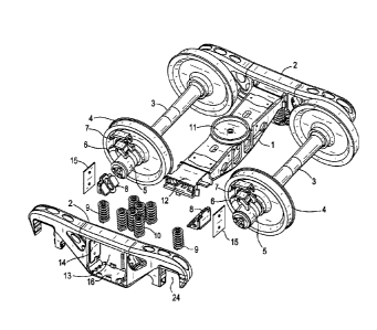
FIG. 1 is an exploded perspective view of a railway car truck in accordance
with an embodiment
of the present invention;
FIG. 2 is a detailed partial perspective view of a portion of a railway car
truck in accordance with
an embodiment of the present invention;
DETAILED DESCRIPTION OF THE PREFERRED EMBODIMENT
Referring now to Fig. 1, a friction shoe 8 of the present invention is shown
in a railroad
car truck. The railway car truck includes two side frames 2 which are spaced
apart and generally
parallel to one another. Each side frame 2 includes a window 13 formed by a
pair of spaced apart
vertical columns 14. A planar column wear plate 15 is connected to the
interior surface of each
side frame vertical column 14. The railway car truck also includes a bolster 1
which extends
generally transversely between the side frames 2. Each end 12 of the bolster 1
is located within a
respective side frame window 13 and is vertically supported on a side frame 2
by a plurality of
helical coil suspension load springs 10. Suspension load springs 10 are
themselves supported on
2
CA 2985102 2017-11-07

= H8324324CA
a spring seat 16 of each sideframe 2. Suspension load springs 10 are
resiliently compressible to
thereby allow the ends of the bolster 1 to move vertically upwardly and
downwardly within the
windows 13 and with respect to the side frames 2. Each bolster end 12 includes
a plurality of
sloped walls 23. Each sloped wall 23 is adapted to engage a sloped face 20 of
a respective
friction shoe 8. Friction shoe 8 is seen to provide a damping force to the
vertical motion of
bolster 1 while supported on suspension control springs 9 as the railway car
travels on the rails.
Suspension control springs 9 are also supported on the spring seat 16 of each
sideframe 2.
Railway wheels 4 are mounted on axles 3. Axle bearings 5 are mounted on the
ends of
axles 3. Bearing spacer 6 and spacer pad 7 are provided to receive axle
bearings in sideframe
pedestal openings 24. Center bowl 11 on the top surface of bolster 1 is
provided to help support
the railway freight car on the truck.
As best shown in Fig. 2, Friction shoe 8 includes a body 17 and a friction
liner 18. The
friction shoe body 17 includes a generally vertical liner pocket 21 that is
adapted to receive the
friction liner 18. The friction liner 18 functions as the vertical face 19 of
the friction shoe 8. The
friction shoe body 17 is generally triangular or wedge-shaped. The friction
shoe body 17
includes a base having a generally horizontal bottom surface 22. The bottom
surface 22 is
adapted to engage the top end of a suspension control spring 9. The friction
shoe body 17 also
includes a sloped face 20 that extend at an inclined angle between the bottom
surface 22 and the
vertical face 19. Friction shoe sloped faces 20 are adapted to engage the
sloped walls 23 of the
bolster 1.
Friction shoe friction liner material of choice is RF-55 from Scan-Pac
Manufacturing.
The damping force by the friction shoe friction liner material can vary as may
be selected
from the various materials for friction liner 18 and the thickness of friction
liner 18 and degree
3
CA 2985102 2017-11-07

= H8324324CA
the vertical face is impinged against side frame column wear plate 15 and the
angle of the bolster
pocket slope wall 23.
Such damping forces can vary from 700 to 16,250 pounds with a velocity range
of movement of
the friction shoe friction liner of between 0 and 19 inches per second.
Normal force to the friction liner 18 can vary from 2000 to 12,000 pounds.
4
CA 2985102 2017-11-07

Representative Drawing
A single figure which represents the drawing illustrating the invention.
Administrative Status

For a clearer understanding of the status of the application/patent presented on this page, the site Disclaimer , as well as the definitions for Patent , Administrative Status , Maintenance Fee  and Payment History  should be consulted.

Administrative Status

Title Date
Forecasted Issue Date Unavailable
(22) Filed 2017-11-07
Examination Requested 2017-11-07
(41) Open to Public Inspection 2018-06-12
Dead Application 2020-08-31

Abandonment History

Abandonment Date Reason Reinstatement Date
2019-04-30 R30(2) - Failure to Respond
2020-08-31 FAILURE TO PAY APPLICATION MAINTENANCE FEE

Payment History

Fee Type Anniversary Year Due Date Amount Paid Paid Date
Application Fee $400.00 2017-11-07
Registration of a document - section 124 $100.00 2017-11-07
Request for Examination $800.00 2017-11-07
Owners on Record

Note: Records showing the ownership history in alphabetical order.

Current Owners on Record
AMSTED RAIL COMPANY, INC.
Past Owners on Record
None
Past Owners that do not appear in the "Owners on Record" listing will appear in other documentation within the application.
Documents

To view selected files, please enter reCAPTCHA code :


To view images, click a link in the Document Description column. To download the documents, select one or more checkboxes in the first column and then click the "Download Selected in PDF format (Zip Archive)" or the "Download Selected as Single PDF" button.

List of published and non-published patent-specific documents on the CPD .

If you have any difficulty accessing content, you can call the Client Service Centre at 1-866-997-1936 or send them an e-mail at CIPO Client Service Centre.


Document
Description 
Date
(yyyy-mm-dd) 
Number of pages   Size of Image (KB) 
Abstract 2017-11-07 1 22
Description 2017-11-07 4 148
Claims 2017-11-07 4 79
Drawings 2017-11-07 2 61
Representative Drawing 2018-05-08 1 24
Cover Page 2018-05-08 2 63
Examiner Requisition 2018-10-30 4 217