Note: Descriptions are shown in the official language in which they were submitted.
Foldable Five-Star Foot
BACKGROUND OF THE DISCLOSURE
[0001] Technical Field
[0002] The present disclosure belongs to the technical field of base structure
of
supporting devices, and in particular relates to a foldable five-star foot.
[0003] Description of the Related Art
[0004] Swivel chair feet are also called five-star feet, which are common
accessories
of swivel chairs and office chairs. The swivel chair feet are equipped with
lifting cylinders
to support swivel chairs. The existing swivel chair feet are usually radiative
integrated
structures. On one hand, when one of the legs is broken, the whole five-star
foot is
required to be replaced, causing unnecessary waste. On the other hand, the
integrated
structure occupies space, in particular the space of container when the five-
star foot is
stored or transported, resulting in high transport cost and increasing
expenses of
enterprises. Existing easily operable foldable five-star feet are easily
folded, but the use
strength of the five-star feet is lowered by different degrees. Besides, among
the existing
products, the folded feet tend to separate from the center body, adding
unnecessary
complicated operations for the next installation. Moreover, existing five-star
feet have the
problem of tending to unfold by accidents after being folded, affecting use.
[0005] A Chinese patent with patent number CN 105124963 A, published on Dec.
9,
2015, discloses a five-star foot capable of contained, including a center body
and legs
disposed on the center body, wherein the center body is provided with mounting
portions
corresponding to the legs; the legs are hinged with the mounting portions; the
center body
is provided with limiting mechanisms for limiting the rotation of the legs;
and the legs and
the center body are connected in a hinged way, and the legs are limited and
fixed through
the limiting mechanisms.
3032P-F5F-CAP1 1
CA 2985211 2017-11-10
[0006] However, such five-star foot has problems of unstable structure and
poor
service effect.
BRIEF SUMMARY OF THE DISCLOSURE
[0007] The objective of the present disclosure is to provide a foldable five-
star foot
that can complete the connection and fixation of the legs and the center
through an
efficient clamping structure, and ensure that the five-star foot is capable of
being
effectively folded. The five-star foot has the advantages of simple and
reliable structure,
convenient folding, large application scope and easy popularization.
[0008] The technical solution adopted by the present disclosure to solve the
above
problems is as follows. A foldable five-star foot includes a center body and
five legs; each
one of the legs is provided with a first mounting block and a second mounting
block,
wherein each one of the first mounting blocks corresponds to a first mounting
groove,
each one of the second mounting blocks corresponds to a second mounting
groove, the
first mounting groove and the second mounting groove are formed on the center
body;
wherein the first mounting groove and the second mounting groove are both
internally
provided with a pair of a first connecting block and a second connecting
block, each one
of the first connecting blocks is connected with each corresponding one of the
first
mounting blocks, and each one of the second connecting blocks is connected
with a
corresponding one of the second mounting blocks. In this technical solution,
the mode of
matching between two grooves and two connecting blocks is adopted, so the five-
star foot
has advantages of high connection strength and good plastic molding effect
along with
preventing plastics from shrinking and collapsing.
[0009] According to a further preferred technical solution, each one of the
first
mounting blocks is provided with a first connecting groove; each one of the
second
mounting blocks is provided a second connecting groove; each one of the first
connecting
3032P-FSF-CAP1 2
CA 2985211 2017-11-10
grooves is clamped with each corresponding one of the first connecting blocks
and each
one of the second connecting grooves is clamped with each corresponding one of
the
second connecting blocks to connect and fix each corresponding one of the
legs.
[00010] According to a further preferred technical solution, each one of the
first
connecting blocks is provided with a first limiting block for limiting and
fixing each
corresponding one of the unfolded legs, and each one of the first mounting
blocks and
each one of the second mounting blocks arc provided with a first limiting
portion matched
with each corresponding one of the first limiting blocks.
[00011] According to a further preferred technical solution, each one of the
second
connecting blocks is provided with a second limiting block for limiting and
fixing each
corresponding one of the unfolded legs; each one of the first mounting blocks
and each
one of the second mounting blocks are provided with a second unfolding
limiting portion
and a second folding limiting portion, wherein each one of the second
unfolding limiting
portions and each one of the second folding limiting portions are matched with
each
corresponding one of the second limiting blocks, in the technical solution,
the second
limiting blocks located in the middle portions of the first mounting grooves
and the second
mounting grooves has an effect of limiting and fixing the unfolded and folded
legs,
playing the majority of the limiting and fixing role from the axial middles of
the legs, and
ensuring the strength and stability of the fixed connection.
[00012] According to a further preferred technical solution, each one of the
first
mounting blocks and each one of the second mounting blocks are respectively
provided
with a connecting block slide through which each one of the first connecting
blocks passes
to enter each corresponding one of the first connecting grooves; a connecting
block
clamping point which prevents each one of the first mounting blocks from
slipping out
and protrudes toward the inside of each one of the connecting block slides is
disposed
between each one of the connecting block slides and each corresponding one of
the first
3032P-FSF-CAP1 3
CA 2985211 2017-11-10
connecting grooves; and each one of the first connecting grooves is provided
with a
clamping point open cavity in which each one of the clamping block clamping
points
deforms and rebounds. In the technical solution has the advantage of ensuring
that the first
connecting is smoothly clamped and preventing the first connecting block from
slipping
off by accident. The connecting block clamping point rebounds after the first
connecting
block enters the first connecting groove, playing the role of preventing the
first connecting
block from slipping off to a limited degree; besides, the clamping point
cavity ensures that
the connecting block clamping block is capable of smoothly moving back when
the legs
are removed out, namely when the first connecting block is pulled out, thus
ensuring
smooth dismantling of the leg.
[00013] According to a further preferred technical solution, the distance from
an end
corner of each one of the connecting block clamping points that protrudes
toward each
corresponding one of the sliding block connecting slides to a lateral side of
each
corresponding one of the connecting block slides h is 0.5-3.0cm. In the
technical solution,
the connecting block clamping point has the characteristic that the
inclination angle of a
lateral side which is connected with the connecting block slide is smaller
than the
inclination angle of the upper shorter side of the connecting block clamping
point,
ensuring that the first connecting blocks enters the first connecting groove
without much
labor and slides out of the first connecting groove with much labor; moreover,
the distance
reserved between the connecting block clamping point and the connecting block
slide for
the slip-out action is smaller than the distance of the connecting block
slide, and the whole
connecting block slide is the path where the first connecting block speeds up
in sliding to
enter the first connecting groove, so the entrance of the first connecting
block is more
difficult than slipping off, ensuring the connection effect of the legs.
[00014] According to a further preferred technical solution, the center body
is
provided with an upper stopper portion, and each one of the legs is provided
with a leg
3032P-FSF-CAP I 4
CA 2985211 2017-11-10
upper protruding portion that is matched with the upper stopper portion for
limiting and
fixing each corresponding one of the legs. In the technical solution, each one
of the upper
stopper portions, matched with each corresponding one of the leg upper
protruding
portions, serve as the upper limiting and supporting structure of each one of
the legs,
ensuring the stability of the connection structure of the legs and the center
body in the
force bearing state.
[00015] According to a further preferred technical solution, the first
mounting groove
is internally provided with a first mounting block stopper which is clamped
with the first
mounting blocks on each one of the folded legs, wherein the first mounting
block stopper
is provided with first stopper protruding points, each one of the first
mounting blocks is
provided with a first protruding point groove which is clamped with each
corresponding
one of the first stop protruding points; the second mounting groove is
internally provided
with a second mounting block stopper which is matched with the second mounting
blocks
of each one of the folded legs, wherein the second mounting block stopper is
provided
with each second stopper protruding points, and each one of the second
mounting blocks
is provided with a second protruding point groove which is clamped with each
corresponding one of the second stopper protruding points.
[00016] According to a further preferred technical solution, the inner and
outer sides
of each one of the second limiting blocks are two lateral faces which
respectively
correspond to the second unfolding limiting portion and the second folding
limiting
portion and are used to limit and fix each corresponding one of the legs; each
one of the
first limiting blocks is provided with inside faces for limiting and fixing
each
corresponding one of the unfolded legs, and the vertical length and overall
volume of each
one of the second limiting blocks are greater than the vertical length and
overall volume of
each one of the first limiting blocks. In the technical solution, the second
limiting blocks
are clamped and limited from the axial middle portions of the legs; as the
main clamping
3032P-FSF-CAP I 5
CA 2985211 2017-11-10
components in the axial direction, the second limiting blocks are bigger than
the first
limiting blocks, ensuring the effect of "main bearing and clamping point in
the middle,
and auxiliary clamping points on two sides", and ensuring the connection
strength of the
legs 2 and the center body.
[00017] According to a further preferred technical solution, each one of the
first
mounting blocks is provided with a mounting black notch and each one of the
second
mounting blocks is provided with a mounting block notch. In the technical
solution, the
mounting block notches prevent the thicker parts of the first mounting blocks
and the
second mounting blocks from shrinking and collapsing, avoiding the collapse
caused by
large thickness, ensuring strength in use, and saving materials.
[00018] The present disclosure can complete the connection and fixation of the
legs
and the center through an efficient clamping structure, and ensure that the
five-star foot is
capable of being effectively folded. The five-star foot has the advantages of
simple and
reliable structure, convenient folding, large application scope and easy
popularization.
BRIEF DESCRIPTION OF THE SEVERAL VIEWS OF THE DRAWINGS
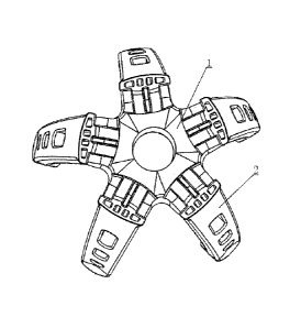
[00019] FIG. 1 is a structural view of the present disclosure in a folded
state;
[00020] FIG. 2 is a structural view of the present disclosure in an unfolded
state;
[00021] FIG. 3 is a schematic view of a side structure a center body in the
present
disclosure;
[00022] FIG. 4 is a schematic view of a side structure of the center body in
the
present disclosure;
[00023] FIG. 5 is a schematic view of a side structure of a leg connection in
the
present disclosure;
[00024] FIG. 6 is a schematic view of a side structure of the leg connection
in the
present disclosure;
3032P-FSF-CAP1 6
CA 2985211 2017-11-10
[00025] FIG. 7 is a structural view of a clamping point position of a
connecting block
in the present disclosure.
DETAILED DESCRIPTION OF THE DISCLOSURE
[00026] The following are merely preferred embodiments of the present
disclosure,
and should not be regarded as limit to the scope of the present disclosure.
[00027] Embodiments: As shown in FIG. 1-7, a foldable five-star foot includes
a
center body 1 and five legs 2. The center body 1 is provided with a first
mounting groove
101a and a second mounting groove 102a for realizing folding and unfolding
actions of
the center body 1 and legs 2 by means of rotation. Correspondingly, each one
of the legs 2
is provided with a first mounting block 201 and a second mounting block 202,
forming
two groups of connecting structures. The first mounting blocks 201 and the
second
mounting blocks 202 are clamped in the first mounting groove 101a and the
second
mounting groove 102a to ensure the reliability and effectiveness of
connection, wherein
the first mounting groove 101a is internally provided with a pair of a first
connecting
block 103 and a second connecting block 104, the second mounting groove 102a
is
provided with a pair of a first connecting block 103 and a second connecting
block 104,
each one of the first connecting blocks 103 is matched with a groove position
on each
corresponding one of the first mounting blocks 201, and each one of the second
connecting blocks 104 is matched with a groove position on each corresponding
one of the
second mounting blocks 202, thus performing clamping connection and limiting
fixation.
In this embodiment, the legs 2 are connected with the center body 1, adopting
the mode of
matching between two grooves and two connecting blocks. Compared with the mode
of
direct clamping between a single groove and a single connecting block, the
present
disclosure has the characteristic of saving materials on the basis of ensuring
strength.
Besides, coordinated with the characteristics of a little narrow outer sides
of the first
3032P-FSF-CAP1 7
CA 2985211 2017-11-10
mounting groove 101a and the second mounting groove 102a and natural elastic
deformation of the inner sides of the first and second mounting grooves, the
clamping
installation is compact and firm. In particular, when the five-star foot is
made of plastics
and when the plastic block has a relatively large thickness, the injection
plastic products
tend to present shrinkage and collapse of different degrees according to the
existing
molding processing conditions, and the collapse degree is directly relevant to
the thickness
of the plastic block. The two-groove structure adopted just reduces the
thickness of the
plastic block at the joint, lowers the effects of the plastic collapse on the
quality of the
five-star foot itself, and also ensures the strength of connection between the
center body 1
and the legs 2.
[00028] Each one of the first mounting blocks 201 is provided with a first
connecting
groove 203d in a clamping connection with each corresponding one of the first
connecting
blocks 103 and a second connecting groove 204 in a clamping connection with
each
corresponding one of the second connecting blocks 104. Correspondingly, each
one of the
second mounting block 202 is also provided with a first connecting groove 203d
in a
clamping connection with each corresponding one of the first connecting blocks
103 and a
second connecting groove 204 in a clamping connection with each corresponding
one of
the second connecting blocks 104. The first connecting grooves 203d are
disposed in pair
on the outer side of each one of the first mounting blocks 201 and on the
outer side of each
one of the second mounting blocks 202.The second connecting grooves 204 are
disposed
in pair on the inner side of each one of the first mounting blocks 201 and on
the inner side
of each one of the second mounting blocks 202. Such configuration mode
corresponds to
the inside-outside position relationship in which the first connecting blocks
103 are
disposed on two sides of the first mounting groove 101a and on the two sides
of the
second mounting groove 102a and the second connecting blocks 104 stand upright
on a
3032P-FSF-CAP1 8
CA 2985211 2017-11-10
partition board between the first mounting groove 101a and the second mounting
groove
102a.
[00029] In this embodiment, each one of the first connecting blocks 103 is
provided
with a first limiting block 105 for limiting each corresponding one of the
legs 2 after each
corresponding one of the legs 2 is completely unfolded; each one of the first
limiting
blocks 105 is effectively clamped with a first unfolding limiting portion 205
disposed on
each one of the legs 2, wherein the first limiting portions 205, also
corresponding to the
characteristic, namely two sides of each one of the first connecting blocks
103, are also
respectively disposed on two outer sides of each one of the first mounting
blocks 201 and
on the two outer sides of each one of the second mounting blocks 202, limiting
and fixing
each one of the legs 2 from two sides thereof, and playing a one-to-one
correspondence
role.
[00030] Similarly, each one of the second connecting blocks 104 is provided
with a
second limiting block 106 for limiting each corresponding one of the legs 2
after each
corresponding one of the legs 2 is completely unfolded; each one of the second
limiting
blocks 106 is effectively clamped with a second unfolding limiting portion
206b disposed
on each one of the legs 2, wherein each one of the second unfolding limiting
portions
206b, also corresponding to the characteristic, namely the middle position of
each one of
the second connecting blocks 104, is clamped and fixed with the axial middle
position of
each one of the legs 2, ensuring the main fixing effect. The two second
unfolding limiting
portions 206b are respectively disposed on the inner side of each one of the
first mounting
blocks 201 and on the inner side of each one of the second mounting blocks
202, playing a
one-to-one correspondence role.
[00031] The difference between the second limiting block 106 and the first
limiting
block 105 is as follows. Each one of the second limiting blocks 106 is
provided with two
planes for limiting and fixing, wherein the plane close to the inner sides of
the first
3032P-FSF-CAP1 9
CA 2985211 2017-11-10
mounting groove 101a and the second mounting groove 102a is matched with each
one of
the second unfolding limiting portions 206b when each one of the legs 2 is
completely
unfolded, realizing unfolding limiting; the other plane of each one of the
second limiting
block 106 that is away from the inner sides of the first mounting blocks 201
and the
second mounting blocks 202 is used for realizing folding limiting on each one
of the legs
2 after each one of the legs 2 is completely folded. The limiting function is
conducted by
means of the second folding limiting portions 206a disposed on the inner sides
of the first
mounting groove 101a and the second mounting groove 102a. The key is that,
when the
rotating angle is of each one of the legs 2 from the unfolding state to the
folded state is a,
each one of the second folding limiting portions 206a and each one of the
second
unfolding limiting portions 206b serve as two limiting planes, forming an
included angle
which should be also be a, and the two planes should be vertical tangent faces
which
constitute the round ring of each one of the second connecting grooves 204,
wherein a is
in a scope of 90 -110 , In this way, it can be ensured that the clamping and
fixing effects
are obtained in the unfolding state and the folded state. In this embodiment,
each one of
the second limiting blocks 106 is a "main limiting block" with a dual effect
of unfolding
limiting and folding limiting, having a "long and large" characteristic in
comparison with
each one of the first limiting blocks 105. Each one of the first limiting
blocks 105 merely
has a relatively small limiting plane for unfolding limiting, and is a small-
sized protruding
"auxiliary limiting block". The design of performing main limiting in the
middle of each
one of the legs 2 and auxiliary limiting on two sides of each one of the leg
2, compared
with the design of performing main limiting on two sides of each one of the
leg 2, has the
advantages of preventing the legs 2 from being broken to the maximum extent,
ensuring
limiting strength, saving materials and simplifying manufacturing process.
[00032] In the process that the legs 2 are installed on and clamped with the
center
body 1, each one of the second connecting blocks 104 is directly clamped in
each
3032P-FSF-CAP1 10
CA 2985211 2017-11-10
corresponding one of the open connecting grooves 204, realizing simple and
effective
clamping and fixing. However, when each one of the first connecting blocks 103
is
clamped in each corresponding one of the first connecting grooves 203d from
the outer
sides of each corresponding one of the first mounting blocks 201 and each one
of the
second mounting blocks 202, a docking link and an anti-slipping off treatment
are needed
for the purpose of, first, ensuring the most basic feasibility and
effectiveness of the
clamping action, and second, ensuring the persistence and durability after the
legs 2 are
clamped and fixed.
[00033] In this embodiment, in order to ensure the feasibility and
effectiveness of the
clamping action, each one of the first mounting blocks 201 and each one of the
second
mounting blocks 202 are both provided with a connecting block slide 203a on
respective
outer side for the purpose of allowing each one of the first connecting blocks
103 to enter
each corresponding one of the first connecting grooves 203d to complete the
clamping
action, and a connecting block clamping point 203b which extends toward the
interior of
each one of the connecting block slides 203a is disposed at a lateral position
between each
corresponding one of the sliding block slides 203a and each corresponding one
of the first
connecting blocks 203d. When each one of the first connecting block clamping
points
203b enters each corresponding one of the first connecting grooves 203d, each
one of the
connecting block clamping points 203b generates deformation toward a lateral
side of
each corresponding one of the connecting block slides 203a due to extrusion by
each
corresponding one of the first connecting blocks 103, so that each one of the
first
connecting blocks 103 can smoothly enter each corresponding one of the first
connecting
blocks 203d, and after each one of the first connecting blocks 103 enters each
corresponding one of the first connecting grooves 203d, each one of the
connecting block
clamping points 203b rebounds and recovers to the original shapes and
positions due to
the disappearance of the extrusion effect, ensuring that the each one of the
first connecting
3032P-FSF-CAP1 11
CA 2985211 2017-11-10
blocks 103 is prevented from slipping out of each corresponding one of the
first
connecting grooves 203d, ensuring the firmness of connection between the legs
2 and the
center body 1, and avoiding damage caused by separation between the legs and
the center
body during storage and transportation. In order to ensure the effectiveness
of the
deformation action after the connecting block clamping points 203b are
extruded, each
one of the connecting block slides 203a is provided with a clamping point open
cavity
203c reserved for each one of the connecting block clamping points 203b, and
each one of
the clamping point open cavities 203c used for accommodating each
corresponding one of
the connecting block clamping points 203b when each corresponding one of the
connecting block clamping points 203b deforms toward the lateral side and used
for
ensuring smooth rebounding achieves the effect of preventing each
corresponding one of
the first connecting blocks 103 from slipping out, and ensures the
effectiveness of the
deformation action. In this embodiment, each one of the connecting block
clamping points
203b extends toward the interior of each corresponding one of the connecting
block slides
203a at a distance h of 0.5-3.0cm, and it is ensured that after each one of
the first
connecting blocks 103 completely enters each corresponding one of the first
connecting
grooves 203d, each one of the connecting block clamping points 203b can
smoothly
rebound to recover the initial state, and then the anti-slipping off effect is
obtained.
Moreover, the extending distance h of each one of the connecting block
clamping points
203b is suitable, so the dismantling of the legs 2 can be smoothly
implemented, ensuring
the persistence and durability of the clamping and fixing of the legs 2.
[00034] After the clamping between the legs 2 and the center body 1 is
completed,
two groups of structures for realizing and strengthening the limiting and
clamping effects
exist between the legs 2 and the center body 1. The first clamping structure
includes two
parts, namely an upper stopper portion 107 disposed on the center body 1 and a
leg upper
protruding portion 207 disposed at the upper position of the front end of each
one of the
3032P-FSF-CAP1 12
CA 2985211 2017-11-10
legs 2, wherein the two parts are matched to perform limiting, serving as the
main part for
clamping and fixing of the legs 2 and the center body 1, bearing a huge
pressure applied
by the center body 1 onto the legs 2, and ensuring the firmness of the five-
star foot as a
support structure. The second clamping structure includes two parts, namely a
first
mounting block stopper portion 101b and a second mounting block stopper
portion 102b
respectively disposed in the first mounting groove 101a and the second
mounting groove
102a, wherein the two parts are matched with the clamped first mounting blocks
201 and
the second mounting blocks 202. The first mounting block stopper portion 101b
and the
second mounting block stopper portion 102b are respectively clamped with each
one of
the first mounting blocks 201 and each one of the second mounting block 202
from the
outer circular faces, so that the first mounting block stopper portion 101b
and the second
mounting block stopper portion 102b have the characteristic of narrowing from
the top
down and presenting circular arc shaped outer sides, ensuring further clamping
and fixing
of the first mounting blocks 201 and the second mounting blocks 202. On the
other hand,
the first mounting block stopper 101b and the second mounting block stopper
102b are
respectively provided with first stopper protruding points 108 and second
stopper
protruding points 109, wherein each one of the first stopper protruding points
108 is
docked and clamped with a first protruding point groove 208 formed on the
outer circular
face of each one of the mounting blocks 201 and each one of the second stopper
protruding points 109 is docked and clamped with a second protruding point
groove 209
formed on the outer circular face of each one of the second mounting blocks
202, further
ensuring the stability of the clamping action of the legs 2 on the center body
1. In
particular during installation of the five-star foot, the clamping effect of
the first stopper
protruding points 108 and the second stopper protruding points 109 is good
enough to
ensure that the clamping of the legs 2 and the center body 1 is not damaged
when an
installation person holds one of the legs 2 in hand, which means that the
center body 1
3032P-FSF-CAP1 13
CA 2985211 2017-11-10
does not fall down, thus avoiding accidents and finally ensuring the
supporting effect of
the five-star foot.
[00035] In this embodiment, on each one of the first mounting blocks 201 and
on
each one of the second mounting blocks 202, a wheel-shaped protrusion for
forming each
one of the first connecting blocks 203d is provided mounting block notches 210
for
preventing large plastic materials from collapsing during molding. The
mounting block
notches 210 are circularly arrayed and uniformly distributed on each one of
the
wheel-shaped protrusions such that all of the first mounting blocks 201 and
the second
mounting blocks 202 have the characteristic of saving materials on the basis
of possessing
sufficient strength.
[00036] The above is detailed description of preferred embodiments of the
present
disclosure, but the present disclosure is not limited to the above
embodiments. Those
ordinarily skilled in the art can make various modifications with their own
knowledge
within the principle of the present disclosure. All of those modifications
should fall within
the protective scope of the Claims of the present disclosure.
3032P-FSF-CAP1 14
CA 2985211 2017-11-10