Note: Descriptions are shown in the official language in which they were submitted.
1
USE OF SYNGAS COMPRISING CARBON MONOXIDE AND WATER IN THE
SYNTHESIS OF METHANOL
FIELD OF THE INVENTION
The present invention relates to a novel method for methanol
synthesis. More specifically, the invention concerns a novel
treatment of the make-up gas used in a methanol synthesis
loop.
BACKGROUND OF THE INVENTION
Methanol is synthesized from a synthesis gas, which consists
of H2 and carbon oxides, i.e. CO and CO2. The conversion from
syngas can be formulated as a hydrogenation of either carbon
monoxide or carbon dioxide, accompanied by the reverse shift
reaction, and can be summarized by the following reaction
sequence:
CO + 2H2 <-> CH3OH
CO2 + 3H2 <-> CH3OH + H20
CO2 + H2 < - > CO + H20
The conversion is performed over a catalyst, which is most
often a copper-zinc oxide catalyst on an alumina support.
Examples of this catalyst include applicant's catalysts
MK-121 and MK-151 FENCETM.
Producing methanol theoretically requires a synthesis gas
(syngas) with a module M equal to 2. The module M is defined
as
M = (H2-0O2)/(CO+CO2) =
Date Recue/Date Received 2022-05-10
2
As syngas typically also contains inert compounds, the
optimum module may become slightly higher than 2, typically
2.05, allowing purge of the inert compounds which inevitably
also will result in purge of reactants H2, CO and CO2.
For a syngas with a module less than the optimum module as
defined above, surplus carbon oxides are present, and the
module must be adjusted to the required level, e.g. by
recovery of H2 from the purge stream and recycle of the
recovered H2 to the synthesis section. In known processes
this is done by recovering H2 from the purge in a separation
unit, e.g. a PSA unit or a membrane unit, which produces a
H2-enriched gas for recycle and a H2-depleted waste gas.
In a typical methanol production process, make-up gas is
mixed with H2-rich recycle gas and passed to the synthesis
reactor, optionally via a sulfur guard if the make-up gas
contains enough sulfur to impact the lifetime of the
methanol synthesis catalyst. After mixing the make-up gas
with the recycle gas, the combined gas is sent to the
methanol reactor, in which hydrogen and carbon oxides react
to form methanol as shown in the above reaction sequence.
Until now it has been normal practice to add CO2 to the
make-up gas in the methanol synthesis loop in order to
maintain a sufficient selectivity of the methanol synthesis
catalyst. This is because, in general, the selectivity of
the methanol synthesis catalyst decreases when operating at
too high CO/CO2 ratios, which can be compensated for by
increasing the CO2 content in the make-up gas.
Date Recue/Date Received 2022-05-10
3
However, this addition of CO2 to the make-up gas can be a
problem, especially in coal-based methanol plants, because
the CO2 normally will originate from a CO2 removal step,
where the resulting CO2 is received at ambient pressure.
Moreover, this CO2 will normally be contaminated with sulfur.
It has now surprisingly turned out that the problem
mentioned above can be solved by adding water to the make-up
gas instead of CO2.
A number of prior art documents deal with the synthesis of
methanol. Thus, EP 1 080 059 B1 describes a process wherein
methanol is synthesized in a synthesis loop in at least two
synthesis stages from a synthesis gas comprising hydrogen
and carbon oxides. With said process, the problem of using a
preliminary synthesis step or operating at low circulation
ratios, leading to relatively high partial pressures, which
in turn lead to excessive reaction and heat evolution in the
catalyst bed, can be avoided.
Use of more than one methanol reactor is described in US
2010/0160694 Al, which concerns a process for the synthesis
of methanol comprising passing a syngas mixture comprising a
loop gas and a make-up gas through a first synthesis reactor
containing a methanol synthesis catalyst to form a mixed gas
containing methanol, cooling said mixed gas containing
methanol and passing it through a second synthesis reactor
containing a methanol synthesis catalyst, where further
methanol is synthesized to form a product gas stream. This
product gas stream is cooled to condense out methanol, and
unreacted gas is returned as the loop gas to said first
Date Recue/Date Received 2022-05-10
4
synthesis reactor. This set-up includes the use of a
combination of a steam raising converter (SRC) cooled by
boiling water under pressure as the first methanol reactor
and a tube cooled converter (TCC) as the second methanol
reactor.
The use of more than one methanol reactor is also disclosed
in US 8,629,190 B2. Synthesis gas is passed through a first,
preferably water-cooled reactor, in which a part of the
carbon oxides in the gas is catalytically converted to
methanol, and the resulting mixture of synthesis gas and
methanol vapor is supplied to a second, preferably
gas-cooled reactor in series with the first reactor. In said
second reactor, a further part of the carbon oxides is
converted to methanol. The mixture withdrawn from the first
reactor is guided through a gas/gas heat exchanger in which
the mixture is cooled to a temperature below its dew point.
Subsequently, methanol is separated from the gas stream and
withdrawn, while the remaining gas stream is fed to the
second reactor.
US 2009/0018220 Al describes a process for synthesizing
methanol, wherein a make-up gas with a stoichiometric number
or module M (M = ([H2-0O2])/([CO2]+[C0])) of less than 2.0,
preferably less than 1.8, is combined with unreacted
synthesis gas to form a gas mixture, which is used to
produce methanol in a single synthesis reactor. The make-up
gas is obtained by reforming a hydrocarbon feedstock, such
as methane or natural gas, and removing water from the
resulting reformed gas mixture.
Date Recue/Date Received 2022-05-10
5
US 5,079,267 and US 5,266,281 both describe a process for
the production of methanol from synthesis gas produced in a
steam reformer. The synthesis gas is cooled followed by
removal of CO2 and H20 from the gas. Then H20 is removed to
obtain a residual level of H20 of 10 ppm or lower, and CO2 is
removed to obtain a residual level of CO2 of 500 ppm,
preferably 100 ppm or lower. The synthesis gas undergoes
142/C0 stoichiometric adjustment before it is sent to the
methanol synthesis reactor.
Finally, US 7,019,039 describes a high efficiency process
for producing methanol from synthesis gas, wherein the
stoichiometric number or module M = ([H2-0O2])/([CO2]+[C0])
of the make-up gas has been increased to about 2.05 by
rejecting CO2 from the gas mixture for a series of
single-pass reactors.
In none of the prior art documents, the possibility of
replacing the CO2 addition to the make-up gas with an
addition of water is suggested.
SUMMARY OF THE INVENTION
Thus, the present invention relates to a process for
methanol production from synthesis gas.
In the following, the invention will be further described with
reference to the appended Figure 1, which is exemplary and not
to be construed as limiting for the invention.
Date Recue/Date Received 2022-05-10
6
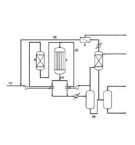
BRIEF DESCRIPTION OF THE DRAWING
Figure 1 shows a plant which can be used for methanol
synthesis.
DETAILED DESCRIPTION
Figure 1 shows a plant which can be used according to the
present invention. The make-up gas (1), to which water has
been added, is mixed with H2-rich recycle gas (2) and passed
to the methanol reactor (A). From this reactor a product
stream and a purge stream are withdrawn. The purge stream is
heated in a preheater and mixed with the process steam to
obtain a mixed stream, which is passed to a shift conversion
unit, where steam and CO react to H2 and CO2. The reacted gas
is cooled to below its dew point in a cooler. The cooled
stream is passed to a process condensate separator, and the
vapor stream from the condensate separator is passed to a
hydrogen recovery unit (D). From this unit a hydrogen-
enriched stream and a hydrogen-depleted waste gas stream are
withdrawn. The hydrogen-enriched gas may be compressed in a
recycle compressor to form the hydrogen-enriched recycle
stream, which is added to the make-up gas (1) as described
above.
The process for methanol production from synthesis gas of
the present invention, comprises:
- providing a make-up gas (1) containing hydrogen and carbon
monoxide, in which the content of carbon dioxide is less
than 0.1 mole%,
Date Recue/Date Received 2022-05-10
7
- mixing the make-up gas (1) with a hydrogen-rich recycle
gas (2) and passing the gas mixture to a methanol synthesis
reactor (A), optionally via a sulfur guard (B), and
- subjecting the effluent (3) from the synthesis reactor (A)
to a separation step, thereby providing crude methanol (4)
and the hydrogen-rich recycle gas (2),
wherein the customary addition of carbon dioxide to the
make-up gas is replaced by addition of water in an amount to
obtain a water content of 0.1 to 5 mole% in the make-up gas
(1).
The amount of added water preferably corresponds to a
content of 0.5 to 2.5 mole%, most preferably 0.8 to 1.2
mole% in the make-up gas.
By adding water to the make-up gas instead of adding carbon
dioxide, the otherwise necessary compression of CO2 is
omitted and thus a CO2 compressor is saved to the benefit of
the process economy.
At the same time, the amount of poisonous sulfur in the
make-up gas is markedly reduced.
The presence of sufficient CO2 in the make-up gas is still
necessary. The improvement over the prior art lies in the
fact that the water addition will ensure sufficient CO2 for
the methanol synthesis via the shift reaction
CO + H20 <-> CO2 + H2.
Date Recue/Date Received 2022-05-10
8
The invention is illustrated further in the examples 1-4,
which follow. The examples illustrate four different cases
with constant converter pressure drop and various make-up
gas (MUG) compositions, viz.
Case 1: No CO2; no H20 in MUG
Case 2: 1 mole% CO2; no H20 in MUG
Case 3: No CO2; 1 mole% H20 in MUG
Case 4: No CO2; 2 mole% H20 in MUG
The carbon loop efficiency listed in the examples is a
direct measure of the methanol synthesis efficiency.
In case 1 the carbon loop efficiency is significantly lower
than in cases 2 to 4. This illustrates the necessity of the
presence of CO2 or a CO2 generator in the make-up gas.
Cases 2 to 4 illustrate that CO2 in the make-up gas can be
replaced by H20 as it is possible to obtain similar carbon
loop efficiencies.
Example 1
This example shows the impact of the MUG composition on the
synthesis loop performance in the base case: 29% CO, 67% H2/
3% N2 and 1% CH4; no CO2 and no H20 in the MUG.
The following results were found:
Recycle ratio 2.799
Steam production 3.535 kg/h
BWR Me0H production 272.795 MTPD
LPS Me0H production 163.873 MTPD
Date Recue/Date Received 2022-05-10
9
HPS Me0H production 178.042 MTPD
Water content in crude Me0H 0.82 wt%
Carbon loop efficiency 11.33%
Carbon BWR reactor efficiency 5.07%
MUG 1.454 Nm3/h
Recycle 4.069 Nm3/h
Flash 80.410 Nm3/h
Purge 1.281 Nm3/h
Total purge 1.282 Nm3/h
Gas compositions, measured as recycle gas composition (RGC),
converter inlet gas composition (CIGC) and converter outlet
gas composition (COGC) were as follows:
RGC CIGC COGC
H2, mole% 66.69 66.77 66.06
CO, mole% 28.04 28.29 27.78
CO2, mole% 0.126 0.093 0.13
N2, mole% 3.400 3.295 3.37
CH4, mole% 1.132 1.097 1.12
Data for the boiling water reactor (BWR):
Space-time yield, kg Me0H/kg catalyst/h 0.210
BWR inlet bed pressure, kg/cm2-g 81.475
BWR outlet bed pressure, kg/cm2-g 79.475
Pressure drop, kg/cm2 2.00
Number of tubes 4405
Total catalyst mass, kg 5.412
Duty of BWR, MW 2.449
Date Recue/Date Received 2022-05-10
10
Temperatures:
BWR temperature, C 230
Approach temperature to Me0H equilibrium, C 179.35
BWR inlet temperature, C 208.00
BWR outlet temperature, C 233.55
Maximum catalyst temperature (hot spot), C 233.91
Example 2
This example shows the impact of the MUG composition on the
synthesis loop performance in case 2: 1 mole% CO2 and no H20
in the MUG.
The following results were found:
Recycle ratio 2.987
Steam production 6.123 kg/h
BWR Me0H production 1.479 MTPD
LPS Me0H production 1.383 MTPD
HPS Me0H production 1.426 MTPD
Water content in crude Me0H 1.525 wt%
Carbon loop efficiency 95.58%
Carbon BWR reactor efficiency 62.62%
MUG 1.454 Nm3/h
Recycle 4.342 Nm3/h
Flash 654.137 Nm3/h
Purge 2.176 Nm3/h
Total purge 2.241 Nm3/h
Gas compositions, measured as RGC, CIGC and COGC were as
follows:
Date Recue/Date Received 2022-05-10
11
RGC CIGC COGC
H2, mole% 67.86 67.65 62.16
CO, mole% 4.952 10.73 4.54
CO2, mole% 1.191 1.143 1.12
N2, mole% 19.334 15.237 17.72
CH4, mole% 6.044 4.779 5.56
Data for the boiling water reactor (BWR):
Space-time yield, kg Me0H/kg catalyst/h 1.139
BWR inlet bed pressure, kg/cm2-g 81.475
BWR outlet bed pressure, kg/cm2-g 79.475
Pressure drop, kg/cm2 2.00
Number of tubes 4405
Total catalyst mass, kg 5.412
Duty of BWR, MW 42.449
Temperatures:
BWR temperature, C 230
Approach temperature to Me0H equilibrium, C 49.67
BWR inlet temperature, C 208.00
BWR outlet temperature, C 240.95
Maximum catalyst temperature (hot spot), C 247.85
Example 3
This example shows the impact of the MUG composition on the
synthesis loop performance in case 3: No CO2 and 1 mole% H20
in the MUG.
The following results were found:
Date Recue/Date Received 2022-05-10
12
Recycle ratio 3.175
Steam production 5.886 kg/h
BWR Me0H production 1.429 MTPD
LPS Me0H production 1.326 MTPD
HPS Me0H production 1.366 MTPD
Water content in crude Me0H 1.606 wt%
Carbon loop efficiency 94.96%
Carbon BWR reactor efficiency 61.69%
MUG 1.454 Nm3/h
Recycle 4.617 Nm3/h
Flash 594.468 Nm3/h
Purge 2.677 Nm3/h
Total purge 2.737 Nm3/h
Gas compositions, measured as RGC, CIGC and COGC were as
follows:
RGC CIGC COGC
H2, mole% 72.71 71.35 67.20
CO, mole% 4.815 10.37 4.45
CO2, mole% 0.996 0.757 0.94
N2, mole% 15.838 12.763 14.64
CH, mole% 5.019 4.057 4.65
Data for the boiling water reactor (BWR):
Space-time yield, kg Me0H/kg catalyst/h 1.101
BWR inlet bed pressure, kg/cm2-g 81.475
BWR outlet bed pressure, kg/cm2-g 79.475
Pressure drop, kg/cm2 2.00
Date Recue/Date Received 2022-05-10
13
Number of tubes 4405
Total catalyst mass, kg 5.412
Duty of BWR, MW 40.778
Temperatures:
BWR temperature, C 230
Approach temperature to Me0H equilibrium, C 58.97
BWR inlet temperature, C 208.00
BWR outlet temperature, C 240.70
Maximum catalyst temperature (hot spot), C 245.90
Example 4
This example shows the impact of the MUG composition on the
synthesis loop performance in case 4: No CO2 and 2mo1e% H20
in the MUG.
The following results were found:
Recycle ratio 3.339
Steam production 5.813 kg/h
BWR Me0H production 1.408 MTPD
LPS Me0H production 1.303 MTPD
HPS Me0H production 1.365 MTPD
Water content in crude Me0H 3.523 wt%
Carbon loop efficiency 96.75%
Carbon BWR reactor efficiency 74.78%
MUG 1.454 Nm3/h
Recycle 4.854 Nm3/h
Flash 538.024 Nm3/h
Date Recue/Date Received 2022-05-10
14
Purge 2.773 Nm3/h
Total purge 2.827 Nm3/h
Gas compositions, measured as RGC, CIGC and COGC were as
follows:
RGC CIGC COGC
H2, mole% 75.94 73.88 70.36
CO, mole% 2.098 7.84 1.95
CO2, mole% 1.121 0.863 1.06
N2, mole% 15.341 12.497 14.22
CH4, mole% 4.894 3.997 4.55
Data for the boiling water reactor (BWR):
Space-time yield, kg Me0H/kg catalyst/h 1.084
BWR inlet bed pressure, kg/cm2-g 81.475
BWR outlet bed pressure, kg/cm2-g 79.475
Pressure drop, kg/cm2 2.00
Number of tubes 4405
Total catalyst mass, kg 5.412
Duty of BWR, MW 40.270
Temperatures:
BWR temperature, C 230
Approach temperature to Me0H equilibrium, C 44.05
BWR inlet temperature, C 208.00
BWR outlet temperature, C 237.36
Maximum catalyst temperature (hot spot), C 246.67
Date Recue/Date Received 2022-05-10