Note: Descriptions are shown in the official language in which they were submitted.
84070054
ENERGY-EFFICIENT INTEGRATED LIGHTING, DAYLIGHTING, AND HVAC WITH
ELECTROCHROMIC GLASS
CROSS-REFERENCE TO OTHER APPLICATION
[0001] This application claims the benefit of the filing date of United States
Provisional Patent Application 62/159,745 filed May 11, 2015. This application
also shares
some subject matter in common with United States Patent Application 14/709,271
filed May 11,
2015, for "Energy-Efficient Integrated Lighting, Daylighting, and HVAC with
Controlled
Window Blinds."
TECHNICAL FIELD
[0002] The present disclosure is directed, in general, to building-control
systems, and in
particular to control of automated lighting, heating, cooling, and
electrochromic glass
systems.
BACKGROUND OF THE DISCLOSURE
[0003] Building automation systems encompass a wide variety of systems that
aid in
the monitoring and control of various aspects of building operation. Building
automation
systems include security systems, fire safety systems, lighting systems, and
HVAC
systems. The elements of a building automation system are widely dispersed
throughout
a facility. For example, an HVAC system may include temperature sensors and
ventilation damper controls, as well as other elements, that are located in
virtually every
area of a facility. These building automation systems typically have one or
more
centralized control stations from which system data may be monitored and
various
aspects of system operation may be controlled and/or monitored.
[0004] To allow for monitoring and control of the dispersed control system
elements,
building automation systems often employ multi-level communication networks to
communicate operational and/or alarm information between operating elements,
such as
sensors and actuators, and the centralized control station. One example of a
building
¨ 1 -
CA 2985603 2019-03-13
CA 02985603 2017-11-09
WO 2016/182592
PCT/US2015/051577
automation system is the Site Controls Controller, available from Siemens
Industry, Inc.
Building Technologies Division of Buffalo Grove, Illinois. ("Siemens"). In
this system,
several control stations connected via an Ethernet, MSTP or another type of
network may
be distributed throughout one or more building locations, each having the
ability to
monitor and control system operation.
- 2 -
CA 02985603 2017-11-09
WO 2016/182592
PCT/US2015/051577
SUMMARY OF THE DISCLOSURE
[0005] This disclosure describes methods for integrated room management in a
building
management system and corresponding systems and computer-readable mediums.
According to one embodiment, a method includes determining a solar heat gain
coefficient (SHGC) for a room in a building, based on the geographic location
of the
room and orientation of the exterior window(s), at a plurality of time
intervals. The
method includes determining predicted open-loop room temperatures ("open-loop"
means with the terminal cooling or heating equipment turned off) for the room
at the
plurality of time intervals based on the SHGC and a plurality of window glass
tint levels.
The method includes determining illumination in the room and the thermal
energy of the
terminal heating or cooling equipment required to condition the room, at each
window
glass tint level and at each time interval, based on the measured exterior
illumination
level of the sun for each window glass tint level, measured artificial
lighting energy
consumed, and measured artificial lighting heat produced to bring the room to
a
predetermined illumination level. The method includes determining room climate
energy, at each of the time intervals, required to maintain the room at a
predetermined
temperature based on the predicted open-loop room temperature response and the
calculated thermal energy of the terminal heating or cooling equipment and
illumination
heat at each of the time intervals. The method includes adding the calculated
thermal
energy of the terminal heating or cooling equipment to thc electrical lighting
thermal
energy to determine a total room energy at each of the time intervals as a
function of the
window glass tint levels based on the room climate energy and illumination
energy
required to condition and illuminate the room. The method includes
determining, from
the total room energy, an optimal glass tint level at each of the time
intervals, wherein the
optimal glass tint level minimizes the total room energy at each of the time
intervals. The
method includes controlling the glass tint levels in the room at each of the
time intervals
according to the optimal glass tint levels, unless there is an override
condition. The
system can enter an override condition in response to detecting beam solar
radiation in
the room. The system can enter an override condition in response to a manual
user
control of the electrochromic glass (ECG) tint level, and thereafter controls
the glass tint
levels according to the manually set tint level.
¨ 3 ¨
84070054
[0006] Another
method includes determining a solar heat gain coefficient (SHGC) for a
room in a building at a plurality of time intervals. The method includes
determining predicted
open-loop room temperatures for the room at the plurality of time intervals
based on the
SHGC and a plurality of electrochromic glass (ECG) tint levels. The method
includes
determining illumination heat and illumination energy for the room, at each
ECG tint level
and at each time interval, based on a measured solar illumination level for
each ECG tint
level, artificial lighting energy consumed, and artificial lighting heat
produced to bring the
room to a predetermined illumination level. The method includes determining
climate energy,
at each of the time intervals, required to maintain the room at a
predetermined temperature
based on the predicted open-loop room temperatures and the illumination heat
at each of the
time intervals. The method includes determining a total room energy at each of
the time
intervals as a function of the ECG tint levels based on the climate energy,
illumination energy,
and predicted room temperatures. The method includes determining, from the
total room
energy, an optimal ECG tint level at each of the time intervals, wherein the
optimal ECG tint
level minimizes the total room energy at each of the time intervals. The
method includes
controlling the ECG tint levels in the room at each of the time intervals
according to the
optimal ECG tint level, unless there is an override condition.
[0006a] According to one aspect of the present invention, there is provided a
method for
integrated room management in a building management system, the method
performed by a
data processing system and comprising: a) determining predicted room
temperatures for a
room at a plurality of time intervals and a plurality of electrochromic glass
(ECG) tint levels;
b) determining an optimal ECG tint level at each of the time intervals,
wherein the optimal
ECG tint level minimizes a total room energy at each of the time intervals;
and c) controlling
the ECG tint levels in the room at each of the time intervals according to the
optimal ECG tint
level.
[0006b] According to another aspect of the present invention, there is
provided a building
management system comprising: i) a processor; ii) an accessible memory; iii) a
climate
control for a room in a building; lighting for the room; and iv)
electrochromic glass (ECG) for
windows of the room, the building management system particularly configured to
a)
- 4 -
CA 2985603 2018-09-12
84070054
determine a solar heat gain coefficient (SHGC) for the room at a plurality of
time intervals; b)
determine open-loop room temperatures for the room at the plurality of time
intervals based
on the SHGC and a plurality of ECG tint levels; c) determine illumination heat
and
illumination energy for the room, at each ECG tint level and at each time
interval, based on an
exterior illumination level for each ECG tint level, artificial lighting
energy consumed by the
lighting, and artificial lighting heat produced by the lighting to bring the
room to a
predetermined illumination level; d) determine climate energy, at each of the
time intervals,
required to maintain the room at a predetermined temperature by the climate
control based on
the predicted room temperatures and the illumination heat at each of the time
intervals; e)
determine a total room energy at each of the time intervals as a function of
the ECG tint levels
based on the climate energy, illumination energy, and predicted room
temperatures; 0
determine, from the total room energy, an optimal ECG tint level at each of
the time intervals,
wherein the optimal ECG tint level minimizes the total room energy at each of
the time
intervals; and g) control the ECG tint level in the room at each of the time
intervals according
to the optimal ECG tint level, unless there is an override condition.
[0007] The
foregoing has outlined rather broadly the features and technical advantages of
the present disclosure so that those skilled in the art may better understand
the detailed
description that follows. Additional features and advantages of the disclosure
will be
described hereinafter that form the subject of the claims. Those skilled in
the art will
appreciate that they may readily use the conception and the specific
embodiment disclosed as
a basis for modifying or designing other structures for carrying out the same
purposes of the
present disclosure. Those skilled in the art will also realize that such
equivalent constructions
do not depart from the spirit and scope of the disclosure in its broadest
form.
[0008] Before undertaking the DETAILED DESCRIPTION below, it may be
advantageous to set forth definitions of certain words or phrases used
throughout this patent
document: the terms "include" and "comprise," as well as derivatives thereof,
- 4a -
CA 2985603 2018-09-12
CA 02985603 2017-11-09
WO 2016/182592
PCT/US2015/051577
mean inclusion without limitation; the term "or" is inclusive, meaning and/or;
the phrases
"associated with" and "associated therewith," as well as derivatives thereof,
may mean to
include, be included within, interconnect with, contain, be contained within,
connect to or
with, couple to or with, be communicable with, cooperate with, interleave,
juxtapose, be
proximate to, be bound to or with, have, have a property of, or the like; and
the term
"controller" means any device, system or part thereof that controls at least
one operation,
whether such a device is implemented in hardware, firmware, software or some
combination of at least two of the same. It should be noted that the
functionality
associated with any particular controller may be centralized or distributed,
whether
locally or remotely. Definitions for certain words and phrases arc provided
throughout
this patent document, and those of ordinary skill in the art will understand
that such
definitions apply in many, if not most, instances to prior as well as future
uses of such
defined words and phrases. While some
terms may include a wide variety of
embodiments, the appended claims may expressly limit these terms to specific
embodiments.
¨ 5 ¨
CA 02985603 2017-11-09
WO 2016/182592
PCT/US2015/051577
BRIEF DESCRIPTION OF THE DRAWINGS
[0009] For a more complete understanding of the present disclosure, and the
advantages
thereof, reference is now made to the following descriptions taken in
conjunction with the
accompanying drawings, wherein like numbers designate like objects, and in
which:
[0010] FIGURE 1 illustrates a block diagram of a building automation system in
which
the energy efficiency of a heating, ventilation, and air conditioning (HVAC)
system may
be improved in accordance with the present disclosure;
[0011] FIGURE 2 illustrates details of one of the field panels of FIGURE 1 in
accordance with the present disclosure;
[0012] FIGURE 3 illustrates details of one of the field controllers of FIGURE
1 in
accordance with the present disclosure;
[0013] FIGURE 4 illustrates a block diagram of a room that can be managed
using
disclosed techniques;
[0014] FIGURE 5 illustrates an example of a system model that can be analyzed
in
accordance with disclosed embodiments;
[0015] FIGURE 6 illustrates an equivalent thermal network for lumped heat
capacities
and thermal resistances of room air and outside walls with room thermal masses
in
corresponding to the system illustrated in Fig. 5; and
[0016] FIGURE 7 illustrates a flowchart of a process in accordance with
disclosed
embodiments.
¨ 6 ¨
CA 02985603 2017-11-09
WO 2016/182592
PCT/US2015/051577
DETAILED DESCRIPTION
100171 FIGURES 1 through 7, discussed below, and the various embodiments used
to
describe the principles of the present disclosure in this patent document are
by way of
illustration only and should not be construed in any way to limit the scope of
the
disclosure. Those skilled in the art will understand that the principles of
the present
disclosure may be implemented in any suitably arranged device. The numerous
innovative teachings of the present application will be described with
reference to
exemplary non-limiting embodiments.
[0018] Disclosed embodiments include systems and methods for optimization of
room
control for the perimeter building zones that have facades with windows with
ECG.
"Optimization- control refers to minimization of energy and maintenance of
acceptable
lighting and thermal comfort conditions for room occupants. Occupant comfort
in a
building environment includes both thermal comfort (temperature and relative
humidity
in the right range) and good lighting conditions (which includes absence or
minimization
of glare). Daylighting, the control of illumination from daylight, will be
adjusted by
means of controlling the ECG tint level. One non-limiting example of an ECG
that can
be used in some implementations is the SageGlass electrochromic glass
manufactured by
SAGE Elcctrochromics, Inc.
[0019] Disclosed embodiments can be used with many different building types,
and are
particularly advantageous for use in office buildings since office buildings
generally
require a given illumination level (e.g. in footcandles or lux) on workplane
surfaces to
provide adequate lighting for its workers.
[0020] Specific terms that may be used herein are described below. A candela
(cd)is a
measure of intensity of light source in a given direction. A do is a unit used
to express
the thermal insulation provided by garments and clothing ensembles, where 1 do
= 0.155
m2- C/W (0.88 ft2-h- F/Btu). Energy (beat) flux refers to energy flow per unit
area
(BTU/hr-ft2). Fenestration is an architectural term that refers to the
arrangement,
proportion, and design of window, skylight, and door systems in a building.
Fenestration
- 7 -
CA 02985603 2017-11-09
WO 2016/182592
PCT/US2015/051577
can serve as a physical and/or visual connection to the outdoors, as well as a
means to
admit solar radiation for daylighting, and for heat gain to a space.
[0021] Footcandles (fc) indicates the density of light landing on a surface,
and is
generally measured in lumens per sq.ft. Glare refers to luminances within the
field of
vision that are too great for the eye to adapt to. The indoor solar
attenuation coefficient
(IAC) represents the fraction of heat flow that enters the room, some energy
having been
excluded by the shading. Depending on the type of shade, it may vary angularly
and with
shade type and geometry. Illuminance is a measure of light incident on a
surface,
generally measured in lumens per sq.ft. Luminance measures the brightness of a
surface
when viewed from a particular direction and is generally expressed in candelas
per square
meter. Lumen (lm) refers to the total amount of light emanating from a light
source. Lux
refers to the International System of Units (SI) unit of light density
equivalent to
footcandles (the English unit), where 1 lux = 1 lumen per square meter.
[0022] The use of daylighting in building designs is increasingly being
recognized as a
primary way to not only reduce electrical lighting energy consumption in
buildings but to
enhance indoor environmental quality (IEQ) for the people (workers) present in
the
building. When designing for maximum daylight, designers must evaluate and
balance a
number of environmental factors, such as heat gain and loss, glare control,
visual quality,
and variations in daylight availability. Daylighting can enhance IEQ in
several ways: by
providing a natural view to the outdoors, providing natural daylight to work
surfaces, and
reducing glare from electrical lighting. Studies have shown that when IEQ is
enhanced,
worker productivity increases, student test scores increase, and absenteeism
is reduced.
100231 Offices with sufficient natural daylight and a visual connection to the
outdoors
have been proven to increase occupant productivity and comfort, leading to
better
employee retention and reduced absenteeism. Successful daylighting designs can
use
diffuse light from the sky through both skylights and window facades, and use
daylighting as the primary source of illumination inside a building.
Successful
daylighting designs when the daylighting controls are integrated with the
electric lighting
¨ 8 ¨
CA 02985603 2017-11-09
WO 2016/182592
PCT/US2015/051577
system provide not only electrical lighting energy savings, but a quality
visual
environment, with worker productivity increases and reduced absenteeism.
[0024] Daylighting reduces the need for electrical lighting of building
interiors, which, if
integrated into the overall approach to lighting, can result in a significant
decrease in
electrical lighting requirements. A well-designed daylit building is estimated
to reduce
lighting energy use by 50% to 80%. According to the U.S. Department of Energy,
the
energy used in U.S. office buildings consumed by HVAC systems accounts for 51%
of
the total energy required and 25% of the lighting energy required. Therefore,
a primary
target for reducing energy consumption in office buildings is to minimize HVAC
and
lighting energy.
[0025] Electrochromic glass (ECG) is glass or glazing whose light transmission
properties are altered when voltage is applied across the thickness of the
glass. Generally,
the opacity of the glass changes from translucent to transparent, changing
from blocking
some (or all) wavelengths of light to letting light pass through. ECG can be
used to
control daylight into a perimeter space by light transmission through the
window glass.
In general, maximizing daylighting will minimize the need for electric
lighting, and while
the maximizing of daylighting will reduce heating loads in winter (the heating
season),
the solar heat gain through windows will also increase cooling loads in summer
(the
cooling season). In addition, in an office environment, direct daylighting
into a space can
also cause glare, and minimization of glare must be included along with
thermal comfort
as the top priority to provide a comfortable environment for employees.
Therefore, one
objective is to provide maximum daylighting for the dynamic shading systems
while
minimizing glare, and then once glare has been minimized (such as on a cloudy
day, or
when the sun is not directly striking the window surfaces) to maximize
daylighting, up to
the point where the cooling load from the added solar heat gain becomes
excessive.
[0026] The general control objectives of the dynamic shading systems can be
summed up
as balancing the need to block direct sunlight, thereby reducing glare and
solar heat gains
during the cooling season, the need to allow the maximum possible amount of
daylight
(and solar heat gain) during the heating season, the need to control direct
sunlight by
¨ 9 ¨
CA 02985603 2017-11-09
WO 2016/182592
PCT/US2015/051577
diffusing it into the space without causing glare on sunny days, the need to
transmit all
available daylight on overcast days, and in general the need to eliminate
glare and create
a pleasant luminous environment.
[0027] Current building management systems cannot integrate lighting and
daylighting
controls with HVAC controls to minimize total energy consumption while
maintaining
occupant comfort. Perimeter zones gain heat and light by the influx of solar
radiation
through the windows, which must be removed by cooling (or less heating) energy
supplied to the space. Cooling and heating the space can be supplied by a
variety of
methods, depending on the type of HVAC supply air distribution system and
terminal
heating/cooling equipment.
[0028] In general, maximizing daylighting in a perimeter zone during the
cooling season
will minimize the need for electric lighting, but may increase cooling loads
in the zone to
maintain the required space temperature conditions, and may cause glare.
Similarly,
maximizing daylighting in a perimeter zone during the heating season will
minimize the
need for electric lighting and reduce heating loads, but may cause occupant
discomfort
from direct sunlight penetrating deep into the space due to the relatively low
position of
the sun in wintertime as it arches across the sky.
[0029] Perimeter zones gain heat and light by the influx of solar radiation
through the
windows, which must be removed by cooling (or less heating) energy supplied to
the
space. Cooling and heating the space can be supplied by a variety of methods,
depending
on the type of HVAC supply air distribution system and terminal
heating/cooling
equipment.
[0030] In general, maximizing daylighting in a perimeter zone during the
cooling season
will minimize the need for electric lighting, but may increase cooling loads
in the zone to
maintain the required space temperature conditions, and may cause glare.
Similarly,
maximizing daylighting in a perimeter zone during the heating season will
minimize the
need for electric lighting and reduce heating loads, but may cause occupant
discomfort
from direct sunlight penetrating deep into the space due to the relatively low
position of
- 10 -
CA 02985603 2017-11-09
WO 2016/182592
PCT/US2015/051577
the sun in wintertime as it arches across the sky. Therefore, there are both
energy and
comfort trade-offs that should be made in the development of the system model.
[0031] When the ECG transmits or passes all or substantially all of the
exterior lighting,
minimal electrical lighting energy is needed but maximum cooling from the
radiant
cooling panels may be needed to meet required space temperature conditions.
Likewise,
when the ECG blocks all or substantially all of the exterior lighting, minimal
radiant
cooling is needed to meet space temperature conditions, but maximum electrical
lighting
may be needed to make up for the loss of daylighting by the high tint level of
the ECG.
In general, an optimal ECG glass tint level exists where total energy
consumption is
minimized.
[0032] However, the general problem of optimizing the ECG tine level to
minimize
energy consumption for a zone can be complex. The amount of daylighting
available is
highly variable, and depends not only on outside sun conditions, passing
clouds, time of
day, and season of year, but also on the design of the ECG itself. In
addition, the
"optimal" ECG tint level that may result in minimal total energy consumption
may also
produce glare conditions within the space and should not be chosen as the
optimal tint
level for the occupants of the space. Therefore, disclosed embodiments include
an
advanced analytical approach that can determine the overall ECG tint level
that will
minimize energy, with the constraint of minimizing glare.
[0033] FIGURE 1 illustrates a block diagram of a building automation system
100 in
which disclosed embodiments can be implemented. The building automation system
100
is an environmental control system configured to control at least one of a
plurality of
environmental parameters within a building, such as temperature, humidity,
lighting
and/or the like. For example, for a particular embodiment, the building
automation
system 100 may comprise the Site Controls Controller building automation
system that
allows the setting and/or changing of various controls of the system. While a
brief
description of the building automation system 100 is provided below, it will
be
understood that the building automation system 100 described herein is only
one example
of a particular form or configuration for a building automation system and
that the system
¨ 11 ¨
CA 02985603 2017-11-09
WO 2016/182592
PCT/US2015/051577
100 may be implemented in any other suitable manner without departing from the
scope
of this disclosure.
[0034] For the illustrated embodiment, the building automation system 100
comprises a
site controller 102, a report server 104, a plurality of client stations 106a-
c, a plurality of
field panels 108a-b, a plurality of field controllers 110a-e and a plurality
of field devices
112a-d. Although illustrated with three client stations 106, two field panels
108, five
field controllers 110 and four field devices 112, it will be understood that
the system 100
may comprise any suitable number of any of these components 106, 108, 110 and
112
based on the particular configuration for a particular building.
[0035] The site controller 102, which may comprise a computer or a general-
purpose
processor, is configured to provide overall control and monitoring of the
building
automation system 100. The site controller 102 may operate as a data server
that is
capable of exchanging data with various elements of the system 100. As such,
the site
controller 102 may allow access to system data by various applications that
may be
executed on the site controller 102 or other supervisory computers (not shown
in
FIGURE 1).
[0036] For example, the site controller 102 may be capable of communicating
with other
supervisory computers, Internet gateways, or other gateways to other external
devices, as
well as to additional network managers (which in turn may connect to more
subsystems
via additional low-level data networks) by way of a management level network
(MLN)
120. The site controller 102 may use the MLN 120 to exchange system data with
other
elements on the MLN 120, such as the report server 104 and one or more client
stations
106. The report server 104 may be configured to generate reports regarding
various
aspects of the system 100. Each client station 106 may be configured to
communicate
with the system 100 to receive information from and/or provide modifications
to the
system 100 in any suitable manner. The MLN 120 may comprise an Ethernet or
similar
wired network and may employ TCP/IP, BACnet, and/or other protocols that
support
high-speed data communications.
¨ 12 ¨
CA 02985603 2017-11-09
WO 2016/182592
PCT/US2015/051577
100371 The site controller 102 may also be configured to accept modifications
and/or
other input from a user. This may be accomplished via a user interface of the
site
controller 102 or any other user interface that may be configured to
communicate with
the site controller 102 through any suitable network or connection. The user
interface
may include a keyboard, touchscreen, mouse, or other interface components. The
site
controller 102 is configured to, among other things, affect or change
operational data of
the field panels 108, as well as other components of the system 100. The site
controller
102 may use a building level network (BLN) 122 to exchange system data with
other
elements on the BLN 122, such as the field panels 108.
[0038] Each field panel 108 may comprise a general-purpose processor and is
configured
to use the data and/or instructions from the site controller 102 to provide
control of its
one or more corresponding field controllers 110. While the site controller 102
is
generally used to make modifications to one or more of the various components
of the
building automation system 100, a field panel 108 may also be able to provide
certain
modifications to one or more parameters of the system 100. Each field panel
108 may
use a field level network (FLN) 124 to exchange system data with other
elements on the
FLN 124, such as a subset of the field controllers 110 coupled to the field
panel 108.
[0039] Each field controller 110 may comprise a general-purpose processor and
may
correspond to one of a plurality of localized, standard building automation
subsystems,
such as building space temperature control subsystems, lighting control
subsystems, or
the like. For a particular embodiment, the field controllers 110 may comprise
the model
TEC (Terminal Equipment Controller) available from Siemens. However, it will
be
understood that the field controllers 110 may comprise any other suitable type
of
controllers without departing from the scope of the present invention.
[0040] To carry out control of its corresponding subsystem, each field
controller 110 may
be coupled to one or more field devices 112. Each field controller 110 is
configured to
use the data and/or instructions from its corresponding field panel 108 to
provide control
of its one or more corresponding field devices 112. For some embodiments, some
of the
field controllers 110 may control their subsystems based on sensed conditions
and desired
¨ 13 ¨
CA 02985603 2017-11-09
WO 2016/182592
PCT/US2015/051577
set point conditions. For these embodiments, these field controllers 110 may
be
configured to control the operation of one or more field devices 112 to
attempt to bring
the sensed condition to the desired set point condition. It is noted that in
the system 100,
information from the field devices 112 may be shared between the field
controllers 110,
the field panels 108, the site controller 102 and/or any other elements on or
connected to
the system 100. In specific embodiments described herein, field devices 112
can include
ECG controllers that control ECG tint levels (the opacity of the glass and how
much light
is passed through the glass), temperature sensors, lighting/illumination
controls or
sensors, beam detectors that detect direct sunlight, and others. In some
embodiments, the
thermal environment of a room can be measured by dry bulb temperature and
relative
humidity sensors that functions the field devices 112.
[0041] In order to facilitate the sharing of information between subsystems,
groups of
subsystems may be organized into an FLN 124. For example, the subsystems
corresponding to the field controllers 110a and 110b may be coupled to the
field panel
108a to form the FLN 124a. The FLNs 124 may each comprise a low-level data
network
that may employ any suitable proprietary or open protocol.
[0042] Each field device 112 may be configured to measure, monitor and/or
control
various parameters of the building automation system 100. Examples of field
devices
112 include lights, thermostats, temperature sensors, fans, damper actuators,
heaters,
chillers, alarms, HVAC devices, and numerous other types of field devices. The
field
devices 112 may be capable of receiving control signals from and/or sending
signals to
the field controllers 110, the field panels 108 and/or the site controller 102
of the building
automation system 100. Accordingly, the building automation system 100 is able
to
control various aspects of building operation by controlling and monitoring
the field
devices 112.
[0043] As illustrated in FIGURE 1, any of the field panels 108, such as the
field panel
108a, may be directly coupled to one or more field devices 112, such as the
field devices
112c and 112d. For this type of embodiment, the field panel 108a may be
configured to
provide direct control of the field devices 112e and 112d instead of control
via one of the
¨ 14 ¨
CA 02985603 2017-11-09
WO 2016/182592 PCT/US2015/051577
field controllers 110a or 110b. Therefore, for this embodiment, the functions
of a field
controller 110 for one or more particular subsystems may be provided by a
field panel
108 without the need for a field controller 110.
[0044] FIGURE 2 illustrates details of one of the field panels 108 in
accordance with the
present disclosure. For this particular embodiment, the field panel 108
comprises a
processor 202, a memory 204, an input/output (I/O) module 206, a communication
module 208, a user interface 210 and a power module 212. The memory 204
comprises
any suitable data store capable of storing data, such as instructions 220 and
a database
222. It will be understood that the field panel 108 may be implemented in any
other
suitable manner without departing from the scope of this disclosure.
[0045] The processor 202 is configured to operate the field panel 108. Thus,
the
processor 202 may be coupled to the other components 204, 206, 208, 210 and
212 of the
field panel 108. The processor 202 may be configured to execute program
instructions or
programming software or firmware stored in the instructions 220 of the memory
204,
such as building automation system (BAS) application software 230. In addition
to
storing the instructions 220, the memory 204 may also store other data for use
by the
system 100 in the database 222, such as various records and configuration
files, graphical
views and/or other information.
[0046] Execution of the BAS application 230 by the processor 202 may result in
control
signals being sent to any field devices 112 that may be coupled to the field
panel 108 via
the I/O module 206 of the field panel 108. Execution of the BAS application
230 may
also result in the processor 202 receiving status signals and/or other data
signals from
field devices 112 coupled to the field panel 108 and storage of associated
data in the
memory 204. In one embodiment, the BAS application 230 may be provided by the
Site
Controls Controller software commercially available from Siemens Industry,
Inc.
However, it will be understood that the BAS application 230 may comprise any
other
suitable BAS control software.
[0047] The I/O module 206 may comprise one or more input/output circuits that
are
configured to communicate directly with field devices 112. Thus, for some
- 15 -
CA 02985603 2017-11-09
WO 2016/182592
PCT/US2015/051577
embodiments, the I/O module 206 comprises analog input circuitry for receiving
analog
signals and analog output circuitry for providing analog signals.
[0048] The communication module 208 is configured to provide communication
with the
site controller 102, other field panels 108 and other components on the BLN
122. The
communication module 208 is also configured to provide communication to the
field
controllers 110, as well as other components on the FLN 124 that is associated
with the
field panel 108. Thus, the communication module 208 may comprise a first port
that may
be coupled to the BLN 122 and a second port that may be coupled to the FLN
124. Each
of the ports may include an RS-485 standard port circuit or other suitable
port circuitry.
[0049] The field panel 108 may be capable of being accessed locally via the
interactive
user interface 210. A user may control the collection of data from field
devices 112
through the user interface 210. The user interface 210 of the field panel 108
may include
devices that display data and receive input data. These devices may be
permanently
affixed to the field panel 108 or portable and moveable. For some embodiments,
the user
interface 210 may comprise an LCD-type screen or the like and a keypad. The
user
interface 210 may be configured to both alter and show information regarding
the field
panel 108, such as status information and/or other data pertaining to the
operation of,
function of and/or modifications to the field panel 108.
[0050] The power module 212 may be configured to supply power to the
components of
the field panel 108. The power module 212 may operate on standard 120 volt AC
electricity, other AC voltages or DC power supplied by a battery or batteries.
[0051] FIGURE 3 illustrates details of one of the field controllers 110 in
accordance with
the present disclosure. For this particular embodiment, the field controller
110 comprises
a processor 302, a memory 304, an input/output (I/O) module 306, a
communication
module 308 and a power module 312. For some embodiments, the field controller
110
may also comprise a user interface (not shown in FIGURE 3) that is configured
to alter
and/or show information regarding the field controller 110. The memory 304
comprises
any suitable data store capable of storing data, such as instructions 320 and
a database
322. It will be understood that the field controller 110 may be implemented in
any other
¨ 16 ¨
CA 02985603 2017-11-09
WO 2016/182592 PCT/US2015/051577
suitable manner without departing from the scope of this disclosure. For some
embodiments, the field controller 110 may be positioned in, or in close
proximity to, a
room of the building where temperature or another environmental parameter
associated
with the subsystem may be controlled with the field controller 110.
[0052] The processor 302 is configured to operate the field controller 110.
Thus, the
processor 302 may be coupled to the other components 304, 306, 308 and 312 of
the field
controller 110. The processor 302 may be configured to execute program
instructions or
programming software or firmware stored in the instructions 320 of the memory
304,
such as subsystem application software 330. For a particular example, the
subsystem
application 330 may comprise a temperature control application that is
configured to
control and process data from all components of a temperature control
subsystem, such as
a temperature sensor, a damper actuator, fans, and various other field
devices. In addition
to storing the instructions 320, the memory 304 may also store other data for
use by the
subsystem in the database 322, such as various configuration files and/or
other
information.
[0053] Execution of the subsystem application 330 by the processor 302 may
result in
control signals being sent to any field devices 112 that may be coupled to the
field
controller 110 via the I/O module 306 of the field controller 110. Execution
of the
subsystem application 330 may also result in the processor 302 receiving
status signals
and/or other data signals from field devices 112 coupled to the field
controller 110 and
storage of associated data in the memory 304.
100541 The I/O module 306 may comprise one or more input/output circuits that
are
configured to communicate directly with field devices 112. Thus, for some
embodiments, the I/O module 306 comprises analog input circuitry for receiving
analog
signals and analog output circuitry for providing analog signals.
[0055] The communication module 308 is configured to provide communication
with the
field panel 108 corresponding to the field controller 110 and other components
on the
FLN 124, such as other field controllers 110. Thus, the communication module
308 may
- 17 -
CA 02985603 2017-11-09
WO 2016/182592
PCT/US2015/051577
comprise a port that may be coupled to the FLN 124. The port may include an RS-
485
standard port circuit or other suitable port circuitry.
[0056] The power module 312 may be configured to supply power to the
components of
the field controller 110. The power module 312 may operate on standard 120
volt AC
electricity, other AC voltages, or DC power supplied by a battery or
batteries.
[0057] The heating and cooling energy being supplied to a zone can be
explicitly defined
and quantified by heat transfer equations, but the amount of daylighting
available from
ECG adjustment is highly variable, depending on outside sun conditions, time
of day,
season of year, and glare considerations. Other objectives include blocking
direct
sunlight, thereby reducing glare and solar heat gains during the cooling
season, allowing
the maximum possible amount of daylight (and solar heat gain) during the
heating
season, controlling direct sunlight by diffusing it into the space without
causing glare on
sunny days, transmitting all available daylight on overcast days, and
eliminating glare
and creating a pleasant luminous environment.
[0058] Glare can be very difficult to measure and extremely complicated to
calculate
analytically. In addition, the perception of glare by the occupants of a
perimeter building
space depends on their viewing directions (e.g. the orientation of their
locations) with
respect to the source of glare. However, glare from windows can be controlled
by
controlling the ECG tint level.
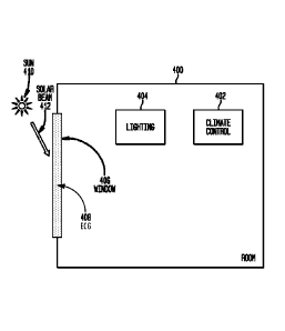
100591 FIGURE 4 illustrates a block diagram of a room 400 that can be managed
using
disclosed techniques. Room 400 includes climate control 402, which can include
heating, cooling, and ventilation systems, all of which consume energy, and
which can
regulate the temperature and humidity of room 400. Room 400 also includes
lighting
404, which consumes energy, and which can be varied in illumination depending
on the
natural light in the room. Room 400 has a window 406 with ECG 408. The sun 410
can
illuminate room 400 through window 406, and the amount of illumination can be
adjusted using ECG 408. Room 400 can lose heat or gain heat through window
406,
depending on weather conditions, the sun 410, the ECG 408, and other factors.
When the
sun 410 has a solar beam 412 (direct sunlight) into window 406, glare in room
400 can be
¨ 18 ¨
CA 02985603 2017-11-09
WO 2016/182592
PCT/US2015/051577
a significant problem, but disclosed embodiments can adjust the tint level of
ECG 408 to
control glare. Glare control can be used to override the calculated optimum
ECG tint
level described below (to minimize total energy consumption) whenever solar
beam
radiation is detected during occupied hours. In the specific example of the
process
below, the climate control 402 is implemented as radiant heating and cooling
ceiling
panels.
[0060] Disclosed embodiments can use an analytical process for managing energy
consumption based on finding the room temperature response to solar radiation
from
various ECG tint levels, for any time of day or season of year. This can
include solving
two coupled first-order differential equations. A differential equation can be
used to
properly model the room temperature response to incoming solar radiation
through ECG
system since, in the real world, room temperature does not respond instantly
to incoming
solar radiation through ECG, but lags in time response due to the thermal
capacitance of
the room and heat flows into and out of the room.
[0061] FIGURE 5 illustrates an example of a system model that can be analyzed
in
accordance with disclosed embodiments. This example illustrates a system with
a radiant
ceiling panel system used for terminal heating and cooling, but those of skill
in the art
will recognize that with only minor changes to the mathematics, this basic
solution
approach can be applied to a wide variety of terminal heating or cooling
devices.
[0062] FIGURE 5 illustrates a number of system elements that represent energy
and heat
transferred into and out of a room 502 having electrical lighting 504 and
radiant ceiling
panels 506. Fig. 5 also illustrates a window 508 with ECG 510. In this figure
or as
described herein,
= = supply duct air pressure;
= = air pressure in adjacent space (or outside air pressure);
= l. = supply air temperature;
= T = room air temperature;
= T, = weighted average wall temperature;
¨ 19 ¨
CA 02985603 2017-11-09
WO 2016/182592
PCT/US2015/051577
= rh = supply air mass flow rate;
= rh = exhaust air mass flow rate;
= rilexf = exfiltration air mass flow rate;
= h,õ = supply air cnthalpy;
= P = room air pressure (absolute);
= T T= room (dry bulb) air temperature (absolute);
= = air (dry bulb) temperature in adjacent space (or outside air dry bulb
temperature);
= m = mass of air in room;
= h = enthalpy of air in room;
= p= density of air in room;
= p,õ = density of supply air to room;
= = energy flux transmission of solar heat through windows;
= 4-õNõ"69t.tma. = thermal heat energy into the space from electric
lighting;
= internal heat generation from people and equipment in room;
= .0,= radiant heat transfer from radiant ceiling panels;
= = convective heat transfer from radiant ceiling panels
= = convection coefficient of inner wall surface of room
= = convection coefficient of outer wall surface of room
= = area of inner wall surface of room
= A = area of outer wall surface of room
= = outside wall thickness
= lcç, kw= thermal conductivity of outside wall
[0063] Note that sign convention used in this figure for energy inflow into
the zone is
positive, and for energy outflow it is negative. The radiative and convective
heat transfer
is shown leaving the zone, which represents a typical cooling application.
¨ 20 ¨
CA 02985603 2017-11-09
WO 2016/182592
PCT/US2015/051577
100641 FIGURE 6 illustrates an equivalent thermal network for lumped heat
capacities of
room air and outside walls with room thermal masses in corresponding to the
system
illustrated in Fig. 5. In this figure, RI represents the area transmittance
between room air
and walls and is equal to the thermal resistance R-value divided by the area
of heat
transfer surface; Ro represents the area transmittance between center of wall
and ambient
surroundings and is equal to the thermal resistance R-value divided by the
area of heat
transfer surface; Cair represents the thermal capacitance of the room air; Cw
represents the
thermal capacitance of the surrounding walls; hi, represents the convection
heat transfer
coefficient at inner wall(s) surface; Ai, represents the area of inner wall(s)
surface; ho,
represents the convection heat transfer coefficient at outside wall(s)
surface; Ao,
represents the area of outside vv-all(s) surface; 1(0, represents the thermal
conductivity of
outside wall(s); and Axoõ represents the thickness of outside wall(s).
[0065] FIGURE 7 illustrates a flowchart of a process in accordance with
disclosed
embodiments for integrated room management in a building management system.
Such a
process can be performed by a data processing system such as building
automation
system 100, and is referred to generically as the "system" below.
[0066] The system can determine a solar heat gain coefficient (SHGC) for a
room in a
building, such as based on the geographic location of the room and orientation
of the
outside window(s), at a plurality of time intervals (702). The time intervals
can be, for
example every fifteen minutes during business hours of a given day, or can be
other
appropriate intervals on a time and date that the room is expected to be
occupied. In
other cases, the SHGC may be given by the manufacturer as a function of the
incoming
solar radiation flux.
[0067] The SHGC can be calculated using the equation:
aT(t,a)
air ¨ PinC 77t )-4g lelect light (t i
at ,
Tõ, ¨ t
(T ,)
(T,õ, ¨ )
R,
SHGC(ti,a,)¨
EtiAp, (cos ,13, cost.)
- 21 -
CA 02985603 2017-11-09
WO 2016/182592
PCT/US2015/051577
where
(
E LSM -LON
= cosL coso cos 15 t; + 12 + sinL- sino
_ 60 15
= lelecilighting is the instantaneous lighting thermal energy output
generated by the
BTU
lights in units of and can be
calculated as
hr
kW
x (3, 413 BTU 1 ht.
elect lighting(derating per dimming level) Nx
l'anIP )elect kW
= Cair is the thermal capacitance of the room air;
= L = Local latitude;
= g = solar declination angle; g = 23.45sin- 360(284+r where 11= the
365
day number of the year;
= Eti =
Equation of time in decimal minutes =9.87s1n(2B)- 7 .53cosB -1.5s ,
= ____________________
where ZE--4 , and 1 = the day number of the year;
= L514= Local Standard Meridian. Standard meridians are found every 15
from 0 at Greenwich, U.K. In the United States and Canada, these values are
(i.e. the values of LSM in the above equation) are:
o Atlantic Standard Time Meridian: 60 W
o Eastern Standard Time Meridian: 75 W
o Central Standard Time Meridian: 90 W
o Mountain Standard Time Meridian: 105 W
o Pacific Standard Time Meridian: 120 W
o Alaska Standard Time Meridian: 135 W
o Hawaii Standard Time Meridian: 150 W
= LON = Local longitude;
= t = local standard time in decimal hours;
- 22 -
CA 02985603 2017-11-09
WO 2016/182592 PCT/US2015/051577
= cosy = cos (q) ¨ vi) = cos (p = cos vf + situp = sinv , where vf is a
fixed value,
depending on the surface azimuth angle orientation of the window;
= ,8 = solar altitude angle above the horizontal;
= y = surface solar azimuth angle;
= 0 = solar azimuth angle. The solar azimuth angle is ZERO at solar noon
and
at solar midnight and increases positively in the counterclockwise direction
for morning hours and increases positively in the clockwise direction for
afternoon hours.
= P = surface azimuth angle. Surfaces that face west have a positive
surface
azimuth tv, while those facing east have a negative surface azimuth tv.
= E = solar irradiance measurement;
= i = the specific time interval;
= Arooffl = floor area of the room (ft2).
= ARcp= area of the radiant ceiling panels (ft2).
= q1, = heat transmission flux through the windows in units of BTU
hr ft2
= Tin = measured indoor air temperature, F;
= T0õ, = measured outdoor air temperature, F;
= T = weighted average wall temperature, F;
= Apf¨ total projected area of fenestration (approximately the window's
opening
in the wall less installation clearances), ft2;
= _________________________________________________ U = overall heat transfer
coefficient of the window BTU, F;
hr ft2
= 4, = radiation heat flux in units of BTU
hr = ft2
BTU
= 4, = heat flux from natural convection in
hr = ft2
= T= measured indoor space dry-bulb air temperature, F;
lb
= P = absolute room air pressure (4);
ft
¨ 23 ¨
CA 02985603 2017-11-09
WO 2016/182592
PCT/US2015/051577
(
ft¨lb
= ___________________________________ R= Gas constant for air = 53.47
lb¨ R1
= V= volume of the room (ftR);
= = the volumetric flow rate of air in, out, or exfiltrating (exf) from the
room;
= ,= constant pressure;
= i i= supply airflow rate into the room
= cõ ,= specific heat of dry air = 0.240 BTU
lb F
,1
= A, = , where R= gas constant for
air (=347 Piõ = the absolute
RT.
212
duct pressure C+3, and 2 = absolute supply air temperature ( R);(10
Ft' lb
= p = ¨, where P= the absolute room
pressure ,
= 4g = internal heat generation from people and equipment in room;
[0068] In general, a subscript i for a variable indicates that it represents
that variable's
value at the time interval I.
[0069] The system determines predicted room temperatures for the room at the
plurality
of time intervals based on the SHGC and a plurality of ECG tint levels (704).
100701 To determine the predicted room temperatures, the system determines the
open-
loop room temperature response at each time interval to get the predicted room
temperature as a function of time, T(t). This can be calculated using:
dT(t) = p.õ1),(T,¨T) 4,1et light (0
dt pV
air
UA (T,õ¨T)+EllApiSHGC(ti(VLT)) T ¨T
+ ________________________________
And
¨ 24 ¨
CA 02985603 2017-11-09
WO 2016/182592
PCT/US2015/051577
dT+V,õ,
dt Roc,,
Where:
1
= ___________ RI - is the thermal resistance to heat transfer (due to
convection) from the
wall to the room
Ax1 w
= ___________ R, __ + is the thermal resistance to heat transfer (due to
convection
110,4 A,õ k 49
and conduction) from the outside wall surface to the room
= C, = põcV is the thermal capacitance of the outside wall
using variables as described herein, and where
= ,8 = solar altitude angle above the horizontal at time interval t=ti;
= SHGC(t,(VLT)) is the solar heat gain coefficient at time interval t=ti,
which
depends on the visible light transmittance (VLT). The value of
sHGc(ti(nr)) can be calculated by the functional relationship between the
VLT and SHGC as shown in below for an exemplary implementation;
= Et, is the measured total solar irradiance (beam + diffuse) at time
interval t=t,
(a constant).
100711 Using this equation, the system can calculate the predicted room
temperature for
the each time interval for each ECG tint level.
[0072] The system determines illumination heat and illumination energy for the
room, at
each ECG tint level and at each time interval, based on an exterior
illumination level for
each ECG tint level, artificial lighting energy consumed, and artificial
lighting heat
produced to bring the room to a predetermined illumination level (706).
[0073] To do so, the system can determine the value of k from direct
measurements of
Et, and /mom using:
- 25 -
CA 02985603 2017-11-09
WO 2016/182592
PCT/US2015/051577
daylighting = kEõ.71pf (A,7,)
using variables as described herein and where
= "room = indoor illumination level (fc);
= /daylight = indoor illumination level from daylighting (fc);
= k = constant of proportionality relating the measured indoor illumination
level
(fc) to the measured solar irradiance flux for the given projected area of
fenestration (Apf) and solar angles f3 and 7 ;
(BTU
= Eti = measured total solar irradiance flux at time interval i
hrji)
= Apf = projected area of fenestration (approximately = window area); and
= f (A,7,)is the functional relationship between solar angles 13 and 7 to
be
established by testing in the room.
[0074] This step can include calculating the predicted workplane surface light
illumination level for each projected ECG tint level, and the heat output of
the lights at
the corresponding dimming level. The artificial lighting energy consumed and
artificial
lighting heat produced to bring the room to the predetermined illumination
level are
measured for the installed lighting 404 based on the energy and heat produced
by the
lighting used to raise I room to the predetermined illumination level. The
energy and heat
required will be less when natural lighting 'daylight is high, and higher when
'daylight is low.
These measurements need only be performed once, at various lighting/dimming
levels,
for the installed lighting 404 in any given room.
[0075] The system determines room climate energy, at each of the time
intervals,
required to maintain the room at a predetermined temperature based on the
predicted
open-loop room temperatures and the illumination heat at each of the time
intervals
(708). For any given climate control 402, the system can determine energy
required to
heat or cool the room to the predetermined temperature from the predicted
temperatures
and the heat produced from the installed lighting 404 (in the amount needed
for to ensure
the illumination level as described above).
¨ 26 ¨
CA 02985603 2017-11-09
WO 2016/182592
PCT/US2015/051577
100761 The system determines a total room energy at each of the time intervals
as a
function of the ECG tint levels based on the climate energy, illumination
energy, and
predicted open-loop room temperatures (710). Here, the system can add the
energy
required to heat or cool the room to the predetermined temperature, by climate
control
402 from the predicted temperatures and for each ECG tint level, to the
illumination
energy required to ensure the predetermined illumination to get a projected
total room
energy curve as a function of the ECG tint levels. The system determines, from
the total
room energy, an optimal ECG tint level at each of the time intervals. The
optimal ECG
tint level is the level that minimizes the total room energy at each of the
time intervals
(712). If the electrochromic glass manufacturer offers continuously variable
tint levels
for their ECG, this can be performed by taking the first derivative (or
minimum) of this
projected total room energy curve with respect to the ECG tint level, setting
it equal to
zero, and solving for the ECG tint level. This will be the optimal ECG tint
level that
minimizes the total room energy, while maintaining occupant comfort for
illumination
and temperature. In various embodiments, the optimal ECG tint level provides
external
illumination to the room while preventing glare.
[0077] The system can control the ECG tint levels in the room at each of the
time
intervals according to the optimal ECG tint level (714). Once the optimal ECG
tint levels
for each time interval are known, the system can adjust ECG 408 so that they
are tinted at
the optimal ECG tint level. This can be performed at all times, at each time
interval, only
when the room is occupied, or unless there is an override condition as
described below.
[0078] The system can enter an override condition in response to detecting
beam solar
radiation in the room, which can produce unpleasant glare, and in this
override condition,
control the ECG tint level in the room (716). Such a case may require
additional lighting
or room climate energy since some of the radiant energy from the sun will be
blocked.
[0079] The system can enter an override condition in response to a manual user-
desired
tint level of the ECG in the room, and in this override condition, controls
the ECG tint
levels according to the manual user control (718). Such a case may require
additional or
- 27 -
CA 02985603 2017-11-09
WO 2016/182592
PCT/US2015/051577
even less lighting or climate energy since the amount of radiant energy from
the sun will
be changed.
[0080] The system can enter an override condition in response to a room
condition (720).
For example, the system can determine that the room is empty, so no lighting
is required,
that it is night, so there is no external lighting and the ECG tint level can
be completely
opaque, substantially transparent, or otherwise.
[0081] Of course, those of skill in the art will recognize that, unless
specifically indicated
or required by the sequence of operations, certain steps in the processes
described above
may be omitted, performed concurrently or sequentially, or performed in a
different
order.
[0082] Those skilled in the art will recognize that, for simplicity and
clarity, the full
structure and operation of all data processing systems suitable for use with
the present
disclosure is not being depicted or described herein. Instead, only so much of
a system as
is unique to the present disclosure or necessary for an understanding of the
present
disclosure is depicted and described. The remainder of the construction and
operation of
data processing system 100 may conform to any of the various current
implementations
and practices known in the art.
[0083] It is important to note that while the disclosure includes a
description in the
context of a fully functional system, those skilled in the art will appreciate
that at least
portions of the mechanism of the present disclosure are capable of being
distributed in the
form of instructions contained within a machine-usable, computer-usable, or
computer-
readable medium in any of a variety of forms, and that the present disclosure
applies
equally regardless of the particular type of instruction or signal bearing
medium or
storage medium utilized to actually carry out the distribution. Examples of
machine
usable/readable or computer usable/readable mediums include: nonvolatile, hard-
coded
type mediums such as read only memories (ROMs) or erasable, electrically
programmable read only memories (EEPROMs), and user-recordable type mediums
such
as floppy disks, hard disk drives and compact disk read only memories (CD-
ROMs) or
digital versatile disks (DVDs).
¨ 28 ¨
CA 02985603 2017-11-09
WO 2016/182592
PCT/US2015/051577
100841 Although an exemplary embodiment of the present disclosure has been
described
in detail, those skilled in the art will understand that various changes,
substitutions,
variations, and improvements disclosed herein may be made without departing
from the
spirit and scope of the disclosure in its broadest form.
100851 None of the description in the present application should be read as
implying that
any particular element, step, or function is an essential element which must
be included in
the claim scope: the scope of patented subject matter is defined only by the
allowed
claims. Moreover, none of these claims arc intended to invoke 35 USC 112(f)
unless
the exact words "means for" are followed by a participle.
- 29 -