Note: Descriptions are shown in the official language in which they were submitted.
BORON NITRIDE NANOTUBE NEUTRON DETECTOR
[0001]
[0002]
FIELD OF THE INVENTION
[0003] The present invention relates to detecting thermal neutrons and fast
neutrons by
inclusion of boron nitride nanotubes (BNNTs).
BACKGROUND - INTRODUCTION
[0004] Thermal neutron detectors usually employ materials with 10B (boron
with 10 nucleons,
i.e. 5 protons and 5 neutrons) or 3He (2 protons and 1 neutron). 157Gd, 6Li
and a few other isotopes
are also sometimes used but methods for incorporating them in large volume
detectors have not
been developed with the exception of some 6Li-based efforts.
[0005] Natural boron is approximately 20% 10B and 80% 1 IB. The 10B-based
detectors are
more common because almost all 3He comes from reprocessing nuclear waste, 3He
is in high
demand, and 3He is consequently very expensive. Most 10B-based detectors
utilize BF3 and are
typically a few cm in diameter with the BF3 at typically from one half to
three atmosphere pressure.
BF3 is toxic and must be carefully contained. For 10B, 3He and 6Li -based
detectors, most employ
systems to detect the electronic pulses or light coming from the ionization
produced
1
Date Recue/Date Received 2022-04-13
CA 02985795 2017-11-1D
WO 2016/183455 PCT/US2016/032385
by the resultant decay products as the ions slow down in surrounding media. A
variety of
ionization chambers, multi wire proportional chambers (MWPC), gas electron
multiplier (GEM),
straw tube, solar blind photomultipliers, solid state photomultipliers, linear
strip sensors, etc. are
used. Typical sizes for BF3-based thermal neutron detectors are several cm in
diameter and
length and with associated high voltages in the range of 1,500 ¨ 2,000 volts.
Sizes of 3He-based
thermal neutron detectors range from a few cm in most dimensions to ones for
scientific research
that may approach a meter in area with a several cm in thickness. 6Li-based
detectors typically
disperse 6Li in various plastic scintillator materials. To achieve adequate
sensitivity, 3He-based
detectors frequently require operation at pressures of several atmospheres,
the addition of other
gases such as propane and CF4, and a range of high voltages.
[0006] 3He has a large cross section of 5,330 barns for the absorption of
thermal
neutrons and the reaction proceeds as:
n + 3He p (0.573 MeV) + 3H (0.191 MeV)
While 3He has certain advantage in some implementations for achieving
relatively high spatial
resolution, 3He-based detection has limitations due to its limitations for
making large,
lightweight, and efficient thermal neutron detectors that can operate well at
atmospheric pressure
as well as at pressures from 0.001 atmosphere to over 5 atmospheres.
[0007] The primary limitation for 6Li-based detectors is that they
typically require a solid
or liquid scintillation material that results in unwanted background signals
from other ionizing
particles that may be present in the environment. In addition, the 6Li cross
section for absorption
of thermal neutrons is less than the 10B cross section for absorption of
thermal neutrons.
2
CA 02985795 2017-11-1D
WO 2016/183455 PCT/US2016/032385
[0008] 10B has a large cross section of 3,835 barns for the absorption of
thermal
neutrons that can be exploited for the detection of the presence of thermal
neutrons. The thermal
neutron absorption reaction proceeds as:
94%: n + 10B 4 11B* 4He (1.47 MeV) + 7Li (0.84 MeV) + gamma (0.48 MeV)
6%: n + 10B 11B* 4He (1.78 MeV) + 7Li (1.02 MeV)
The 11B* state lasts about 1E-12 seconds. The gamma, when present, comes from
the decay of
an excited state of 7Li.
[0009] Following absorption of the neutron the 4He and 7Li lose their
kinetic energy by
ionization loss in the surrounding material and the 0.48 MeV gamma, when
present, is absorbed
by the surrounding material. The occurrence of the neutron absorption on the
10B can be
inferred by detecting the ionization losses of the 4He and 7Li ions or for 94%
of the decays or by
detecting the 0.48 MeV gamma when present. Some systems do both. For example,
in some
media the ionization losses produce light that can be detected by photon
detectors such as
photomultiplier tubes, solar blind photomultipliers, silicon photomultiplier
(SiPM) arrays, large
area avalanche photodiodes (LAAPD), etc. MWPCs, GEMs, straw tube and linear
strip detectors
that collect the ion pairs created in the surrounding media can also be used
[0010] Position and time sensitive fast neutron detectors often employ
scattering (also
known as recoil) methods where the fast neutrons scatter from light nuclei,
such as protons or
helium (4He), to produce the respective recoiling protons or helium ions that
then ionize the
surrounding materials. The ionization energy is then detected by scintillation
or proportional
counters. Issues with this methodology include relatively low efficiency and
background noise
from the inclusion of relatively low energy, i.e. slow, neutrons and other
particles in the signal.
Thermalizing fast neutron detectors infer the existence of fast neutrons by
first slowing the fast
3
CA 02985795 2017-11-1D
WO 2016/183455 PCT/US2016/032385
neutrons in hydrogen-rich moderators and then detecting the thermal neutrons.
All of these
methods also have issues with eliminating gamma ray backgrounds through a
variety of
techniques to include pulse shape discrimination. In addition, the
thermalizing methods also
spread the signal that can be much less than a microsecond to time periods of
many tens to
hundreds of microseconds. In addition, methods that rely on producing thermal
neutrons for fast
neutron detection have backgrounds from the presence of other thermal neutrons
that are
typically present. Fast neutron fission chambers are available that typically
use proportional
counter technology. They have good rejection of gamma rays and when made with
238U as
primarily sensitive to fast neutrons. The neutron fission chambers may have
good timing
resolution, but typically are limited in spatial resolution and total cross
section.
BUFF SUMMARY
[0011] A major challenge for neutron detection is to have a cost effective
yet
sufficiently-sensitive detector that provides both spatial and temporal
information over a very
broad range of volumes to include sub-cubic centimeter to many cubic meters.
In addition, the
detector should have excellent rejection of background radiation such as gamma
rays and be able
to discriminate thermal neutrons from fast neutrons. The preferred neutron
detector's spatial and
temporal resolutions in some embodiments should be sufficient to provide
information on the
energies of the thermal and fast neutrons.
[0012] Boron nitride nanotubes (BNNTs) provide a mechanism to finely
distribute 10B
in a scintillating gas, liquid, or solid. Neutrons are detected in a four step
process: 1) absorption
of the neutron on 10B (the Event); 2) decay of the resultant excited state
11B*; 3) 4He and 7Li
decay products ionize the scintillating gas, liquid, or solid; and 4) detect
the resultant scintillation
photons and/or ion pairs.
4
[0013] In the case of fast neutrons, 238U is used as an energy selector
sensitive to fast neutrons
with energies above 0.5 MeV. BNNT or BNNT coated with polymers can be used as
a scaffolding
to finely distribute atoms of 238U. In addition, thin wires and/or sheets of
238U, typically in the
form of alloys of 238U, can be used to distribute the 238U atoms. Fast
neutrons absorb on the
238U and resulting in a fission reaction that releases significant energy.
Photon and/or ion pair
sensitive detectors of appropriate sensitivity and structure are used to
detect the time and location
of the fast neutron Event.
[0014] Some embodiments may take the foul' of a boron nitride nanotube
("BNNT") based
neutron detector comprising: a chamber; at least one photon detector
positioned in the chamber; a
BNNT material positioned in the chamber; and a scintillating material in the
chamber; wherein the
scintillating material is one of a gas and a liquid, and wherein the at least
one photon detector is
positioned to detect at least a portion of photons emitted from ions
traversing the scintillating
material produced by neutron absorption in the chamber. The chamber may
include at least one
mirror surface, such as aluminum, positioned to reflect photons toward the at
least one photon
detector.
[0015] The BNNT material may be in one or more forms, such BNNT aerogels,
wires, rods,
and sheets. In some embodiments particularly suited for thermal neutron
detection, the BNNT
material may include an enhanced fraction of 10B. For example, the BNNT
material may be
formed from a boron feedstock having an enhanced fraction of 10B. Depending on
the form of the
BNNT material, some embodiments may include a scaffolding, to stabilize the
BNNT material
within the chamber.
Date Recue/Date Received 2022-04-13
[0016] The scintillating material may take various forms, and in some
embodiments may be
present in more than one form. For example, in some embodiments the
scintillating material may
be dispersed in the BNNT material. In some embodiments, the BNNT material
comprises a
scintillating material coating. Some embodiments may include a scintillation
gas disposed within
the chamber. In some embodiments, the BNNT material may be positioned in a
scintillation gas.
The scintillation gas may be, for example, at least one of nitrogen, helium,
neon, argon, krypton,
and xenon. In some embodiments, the BNNT material may be suspended in a non-
scintillating
liquid within the chamber.
[0017] BNNT material may be configured in various m an n ers For example,
BNNT material
may form layers or grid-like structures. As one example, BNNT material may be
arranged in
various planes to form a series of planar structures, such as successive
sheets or wire grids. As
another example, BNNT material may be in the form of wires in spaced layers,
such that the
orientation of wires in successive layers is generally orthogonal.
[0018] Some embodiments particularly suited for fast neutron detection may
include a
238U material, which may be, for example, a 238U alloy. The BNNT material may
provide
scaffolding for the 238U material. In such fast neutron embodiments, the BNNT
material may be
formed from a boron feedstock having an enhanced fraction of 1 IB.
[0019] Some embodiments may take the form of a method of detecting neutrons
comprising:
detecting at least a portion of photons emitted from ions traversing a
scintillating material produced
by neutron absorption in a chamber having BNNT material, wherein the
scintillating material is
one of a gas and a liquid. It should be appreciated that the various features
described herein may
be incorporated into the disclosed methods of detecting neutrons.
6
Date Recue/Date Received 2022-04-13
[0020]
Some embodiments may take the form of a BNNT based neutron detection system
comprising a plurality of neutron detectors, each neutron detector comprising:
a chamber; at least
one photon detector positioned in the chamber; a BNNT material positioned in
the chamber; a
scintillating material in the chamber; wherein the scintillating material is
one of a gas and a liquid;
wherein the at least one photon detector is positioned to detect at least a
portion of photons emitted
from ions traversing the scintillating material produced by neutron absorption
in the chamber.
6a
Date Recue/Date Received 2023-01-04
CA 02985795 2017-11-1D
WO 2016/183455 PCT/US2016/032385
DESCRIPTION OF THE DRAWINGS
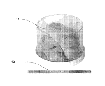
[0021] Fig. 1 shows as-produced BNNT Material,
[0022] Fig. 2 illustrates a neutron being absorbed on a 10B in the BNNT
Material and
emitting light in the surrounding scintillation material.
[0023] Fig. 3 illustrates a side view of a BNNT-based neutron detector.
[0024] Fig. 4 illustrates a 3-D view of a BNNT-based neutron detector.
[0025] Fig. 5 illustrates a cylindrical shaped BNNT-based neutron detector.
[0026] Fig. 6 illustrates a BNNT grid-based neutron detector.
[0027] Fig. 7 illustrates a BNNT planner-based neutron detector.
[0028] Fig. 8 illustrates multiple geometries of a BNNT planner-based
neutron detector.
[0029] Fig. 9 illustrates a large highly segmented BNNT-based neutron
detector.
[0030] Fig. 10 shows data from a BNNT-based neutron detector with xenon
scintillation
gas.
[0031] Fig. 11 shows data from a BNNT-based neutron detector with nitrogen
scintillation gas.
[0032] Fig. 12 shows fission cross sections for neutron capture for a
number of
fissionable materials.
[0033] Fig. 13 shows the absorption cross section for thermal and fast
neutrons on 252Cf.
[0034] Fig. 14 illustrates the absorption of a fast neutron on 238U in a
wire.
[0035] Fig. 15 illustrates a multi wire geometry for spreading the 238U.
[0036] Fig. 16 illustrates a multi wire geometry for spreading the 238U
[0037] Fig. 17 illustrates photon detectors for detecting the light coming
from the fast
neutron induced fission decays in 238U.
7
CA 02985795 2017-11-1D
WO 2016/183455 PCT/US2016/032385
[0038] Fig. 18 illustrates enhanced 238U distribution by the inclusion of
11B BNNT
Material as a scaffolding for dispersing 238U.
[0039] Fig. 19 illustrates a M1NPC method of detecting the fission decays
from fast
neutrons absorbed on 238U.
[0040] Fig. 20 illustrates a MWPC method of detecting the fission decays
from fast
neutrons absorbed on 238U.
DESCRIPTION
[0041] Disclosed herein are thermal neutron detectors, and methods for
neutron
detection, incorporating Boron Nitride Nanotubes. BNNTs can be used to provide
10B-based
thermal neutron detection in large volumes, with high efficiency at
atmospheric pressure, as well
as from 0.001 to 5 atmospheres and with photon detectors that can operate at
voltages below 100
volts as well as with photon detectors that operate at high voltages, e.g.
voltages from 100 volts
to 5,000 volts. In particular, high quality BNNTs, such as those produced by
the high
temperature, method have few defects, no catalyst impurities, 1- to 10-walls
with the peak in the
distribution at 2-walls and rapidly decreasing with larger number of walls.
BNNT diameters
typically range from 1.5 to 6 nm but may extend beyond this range, and lengths
typically range
from a few hundreds of nm to hundreds of microns but may extend beyond this
range. For the as-
produced BNNT material, high quality high temperature method BNNTs typically
make up
about 50% of the bulk material and may have impurities of boron, amorphous BN
and h-BN.
These impurities for the as-produced BNNT material are typically a few lOs of
nm in size or less
but may extend beyond this range. The production parameters of the high
temperature process
can be adjusted to have more or less boron as compared to the amorphous BN and
h-BN
impurities. Having less boron typically increases the optical transparency of
the bulk BNNT
8
CA 02985795 2017-11-1D
WO 2016/183455 PCT/US2016/032385
material. Various purification processes can be used to increase the amount of
BNNTS as
compared to the boron, BN and h-BN impurities. For estimates in this
disclosure, the typical as-
produced material will be considered, and the fraction of boron only impurity
will be considered
negligible, i.e. for BNNT Material all of the material will be considered to
be some form of BN.
The BNNT-based neutron detection process works equally with material at higher
levels of
BNNT purity where the boron, BN and h-BN impurities have been reduced or
eliminated. Thus,
it should be appreciated that the apparatus and methods disclosed herein are
not intended to be
limited to a particular quality of BNNT materials, unless it is explicitly
stated herein.
[0042] The density of the as-produced high temperature method BNNT Material
is
typically roughly 0.5 grams per liter (0.5g/L) and easily varies by +/- 50%.
This value of the "tap
density" can be compared to the density 2,100 g/L for h-BN. Figure 1 shows a
photograph of
BNNT Material 11 produced using a high temperature method. The as-produced
high
temperature method BNNT Material 11 has the appearance of a "puff ball" or
"cotton ball" as
shown in Figure 1, in which the BNNT Material is typically on the scale of
several centimeters to
several tens of centimeters 12. The BNNT material 11 can easily be compacted.
[0043] A BNNT aerogel material can be produced where the tap density is
less than the
0.5g/L density of BNNT material produced by a high temperature method. There
are many
possible methods for generating a BNNT aerogel material. One example is to: 1)
suspend the
BNNT Material in a solvent, such as ethyl alcohol; 2) lightly sonicate the
suspension; 3)
evaporate the liquid from the suspension leaving just the low density aerogel
BNNT Material.
BNNT, BN and h-BN are stable in air to over 900C, so heat can be used.
However, the small
amount of boron present may react with oxygen and possibly nitrogen at
temperatures above
9
CA 02985795 2017-11-1D
WO 2016/183455 PCT/US2016/032385
around 900Cused. The resultant boron oxide can be removed by rinsing with
distilled water. The
evaporation of alcohols, water, and similar materials can be done in vacuum,
air, or nitrogen.
[0044] BNNT Material can be made starting with a boron feedstock consisting
of natural
boron, 10B, and/or 11B. It should be appreciated that boron feedstocks are
available with
varying fractions of natural boron, 10, and 11B. Some boron feedstocks are
available with an
enhanced fraction of either the 10B or the 11B isotope, and are frequently
referred to as
"enriched" in the desired isotope. For purposes of this disclosure, there is
generally no difference
in the synthesis process, or the properties of the resulting BNNT Material,
other than the slight
increase of about 6% in mass in going from pure 10B to pure 11B. BNNT
materials produced
using natural boron, 10B, and 11B resemble the material shown in Figure 1.
[0045] As illustrated in Figure 2, when a neutron 21 interacts with a 10B
22 in a BNNT
or the boron, amorphous RN or h-BN impurities in the BNNT Material 23, 4He ion
24 and 7Li
ion 25 (and possibly gamma) are produced and travel into the surrounding BNNT
Material 23.
The BNNT, boron, amorphous RN and h-BN in the BNNT Material 23 are minimally
changed or
impacted as long as the fraction of material interacted with does not become
significant. The 4He
24 ion gains electrons and remains as a mobile gas species in the
scintillation gas, liquid or solid,
whereas the 7Li 25 may bond to the BNNT, boron, amorphous BN and h-BN or in
some cases
bond to the surrounding scintillation material if it is other than a noble gas
or nitrogen gas. The
7Li bonding has little impact, if any, on the boron species, provided that the
boron species
bonded with 7Li represents a small (<0.1%) fraction of the bulk material and
typically is much
less than this amount.. The 7Li 25 may alternatively interact with the
surrounding gas or other
material that may be present in containment volume 28. The 7Li ion interaction
might become an
issue if the amount of neutrons being absorbed, i.e. the number of Events, was
extremely high, as
CA 02985795 2017-11-1D
WO 2016/183455 PCT/US2016/032385
in the case of placing the detector in close proximity of a nuclear reactor
core. Note, for some
BF3 systems there is a related issue of fluorine atoms releasing that can
interfere with some
modes of detecting the decay signals. The fluorine atom release can become an
issue for BF3 at
relatively lower number of Events as compared to BNNT-based detectors. The
0.48 MeV
gammas are very penetrating to most materials, and largely escape any detector
not explicitly
designed to stop them.
[0046] In some embodiments, detection of 4He ion 24 and 7Li ion 25 produced
in the
neutron 21 absorption on 10B 22, the Event, can be achieved in a two-step
process: 1) surround
the BNNT Material 23 and any boron, amorphous BN, and h-BN impurities, with a
scintillating
material 26, such that as the 4He 24 and 7Li 25 ions lose energy through
ionization, in the
scintillating material light is emitted along the ionization path 27; and 2)
collect the emitted light
and convert it to an appropriate electronic signal. The scintillating material
26 can be a solid,
liquid, or gas. The 4He 24 and 7Li 25 ions may lose some of their energy in
the BNNT Material
23 with its boron, amorphous RN, and h-RN impurities. In some embodiments, the
thermal
neutron detector will be designed such that most of the ionization occurs in
the scintillating
material and relatively small amounts of the ionization occur in the BNNT
Material 23 itself. The
ratio of ionization in the BNNT Material compared to the scintillating
material is controlled by
the ratio of the respective masses of material present with some adjustment
for the atomic
numbers of the materials.
[0047] Embodiments may be configured to decrease the impact of background
noise. For
example, cosmic rays provide a background of energetic muons at a rate of
roughly 1 per 70 mA2
per second-sr with some variation depending on elevation, latitude, etc. These
cosmic rays
typically lose about 2 MeV in ionization energy for every gram/cinA2 they pass
through. This
11
CA 02985795 2017-11-1D
WO 2016/183455 PCT/US2016/032385
means that if the 10B were in a 1 cc cube of plastic or liquid scintillator,
there would be a
background signal mimicking the signal from the neutron capture on 10B about
once every
minute. Some embodiments of a detector are generally larger than lcc, which
may add to the
complexity of extracting signal from the background. For example, a 1 m^2
detector would
likely see at least over one hundred background counts per second. The
resultant background
rates at such surface areas may be much higher than many situations of
interest can tolerate.
Attempting to reduce or eliminate this cosmic rate background can partially be
accomplished
with an array of veto counters, as are known in the neutron detector art, but
such a system may
add further complexity, weight and size. In some embodiments, the BNNT
Material 23 may be
coated with a scintillating material. The coating may be at the molecular
level, and the
scintillating material may form one or more layers on the BNNT material. The
scintillation-
coated BNNTs may be placed in scintillation gas or suspended in a non-
scintillating liquid. This
is possible because BNNTs tend to attract many polymers, and polymer
scintillating materials
can be selected that prefer to stay bonded to the BNNTs and not dissolve into
the non-
scintillating liquid or the wide variety of scintillating liquids that are
available.
[0048] Many environments of interest also have gamma rays present. Most
liquid and
solid scintillators have moderate to high levels of sensitivity to gamma rays
that can be a further
source of background noise. When combining BNNTs into liquid and solid
scintillators, the
scintillating materials chosen can minimize detector's sensitivity to gamma
rays to some degree
depending on the energies of the gamma rays.
[0049] The cross section area of one mole of 10B (10 g) is 6.022E23 x 3,835
barns =
0.23 mA2 where 1 barn ¨ 1E-28 m^2. In embodiments, 10B atoms would be
distributed
throughout the three-dimensional volume of the detector, but even so there
would be some
12
CA 02985795 2017-11-1D
WO 2016/183455 PCT/US2016/032385
openings through which no 10B atom may be present. However, about 10 g of 10B
distributed
over a 0.23 mA2 area provides a reasonable upper bound on the maximum amount
of 10B per
m^2 useful for thermal neutron detection. This results in approximately 40 g
of 10B /m^2, or
about 103 g of BN material/m^2. For simple considerations, a number of about
100 g/m^2 of
BNNT Material (which includes BNNTs with small amounts of boron, amorphous BN,
and h-
BN)) will be used as an upper bound for a certain embodiments of a detector
system as described
herein. It should be appreciated that other embodiments may use larger ratios
of BNNT Material,
and the scope of this disclosure is not intended to be limited to this
specific embodiment.
[0050] As an example, with the tap density of 0.5 g/L, a lmA2 detector,
having a 20 cm
depth, of as-produced high temperature method BNNT Material provides the upper
bound.
[0051] Under these example conditions, embodiments of the thermal neutron
detection
scheme using BNNT Material use a scintillation material that is a gas. In
these embodiments,
most of ionization occurs in the gas and not in the BNNT Material. Available
gases that
scintillate include nitrogen and the noble gases, i.e. helium, neon, argon,
krypton and xenon. In
some embodiments, the scintillating gas will also produce light at wavelengths
that can be
conveniently detected. Most high energy and nuclear physics detectors that use
gas scintillators
work with argon and xenon, though some have certain amounts of helium and
nitrogen. For
working with BNNT Material, in the examples to follow argon will be used, but
it should be
appreciated that other scintillating gases may be used.
[0052] The photons emitted by the scintillation process in argon at
atmospheric pressure
are a combination of 9.7 eV (128 nm) VUV photons and roughly 1.3 eV (940 nm
centered
region) non-UV photons. The amount of ionization energy to create a VUV photon
is 67.9 eV
13
CA 02985795 2017-11-1D
WO 2016/183455 PCT/US2016/032385
and the amount for a non-UV photon is 378 eV. Consequently, each neutron
absorbed on a 10B,
an Event, will generate up to 34,000 VUV photons and 6,000 non-UV photons.
[0053] The BNNT Material will mostly absorb the VUV photons, whereas the
non-UV
photons will be partially absorbed in the BNNT Material. Generally, reducing
the amount of
boron impurity in the BNNT Material reduces the absorption of the non-UV
photons.
[0054] Detecting the light from a neutron absorption Event inside the BNNT
Material as
shown in Figure 2 is conceptually similar to detecting a lightning bolt inside
a cloud. The signal
from the Event depends on: 1) the number of VUV and non-UV photons generated;
2) the
number of VUV and non-UV photons transmitted through the BNNT Material (they
all pass
through argon); 3) internal mirror surfaces that can reflect the photons to
the photon detectors for
those that do not take a direct path; and 4) the efficiency of the photon
detectors for detecting the
VUV and non-UV photons. There is a balance between having sufficient BNNT
Material to
produce Events and having too much BNNT Material between the Event and the
photon
detector. The balance may vary depending on the particular embodiment. Also,
the balance is
dependent on the amount of non-BNNT impurity(ies) in the BNNT Material,
especially, as
indicated above, the amount of boron. For some embodiments, an approximate as
the upper
value for balancing Events and optical transport is around 100 g/mA2.
[0055] Argon at STP has a density of 1.784 g/L. The associated stopping
distance for
4He at 1.47 (1.78) MeV is roughly 0.8 (0.94) cm or alternatively expressed as
roughly 1.4 (1.7)
mg/cmA2 and the stopping distance for 7Li at 0.84 (1.02) MeV is roughly two
thirds these
values. For BN materials including BNNT the stopping range is roughly 0.9
(1.1) mg/cm^2. As
the 4He and 7Li ions are close to traveling in opposite directions (they are
exactly opposite in the
14
CA 02985795 2017-11-1D
WO 2016/183455 PCT/US2016/032385
case of no gamma emission), the total ionization range for the dominate gamma
emitting decay is
roughly 1.5 mg/cm" of BNNT Material.
[0056] Some embodiments for detecting the neutron on 10B will have less
than 1
mg/cm^2 of BNNT Materials including BNNT in at least two directions from any
Event and at
least 1.8 mg/cm^2 of argon, i.e. roughly 1 cm of argon as indicated by the
scale 29 in Figure 2.
[0057] There are two various considerations with respect to the combination
of BNNT
Material and argon or other scintillation material. The 10B preferably is
sufficiently dispersed to
increase the likelihood that the thermal neutrons encounter the 10B and
production an Event.
However, the BNNT Material and anything supporting it will absorb some of the
photons
originating from the 4He and 7Li ionization in the argon (or other
scintillation material), and
may limit observation of Events. Embodiments discussed below provide examples
for balancing
these considerations.
[0058] There are a number of possible detector geometries for producing and
observing
Events. It should be appreciated that features described with respect to an
embodiment below
may be incorporated into other embodiments having different geometries. In
some embodiments,
two general geometries for balancing the production of Events and observing
Events include: 1)
The BNNT Material fairly uniformly dispersed as an aerogel, and in some
embodiments argon
filling the space not occupied by the aerogel. The maximum density of the BNNT
Material
forming the aerogel in some embodiments is about 1 mg/cm^3; in such
configurations the ions
have roughly 1 cm of argon or other scintillation gas available. This geometry
optimizes the
Event generation, but in some embodiments, if the thickness of the BNNT
Material becomes too
great for the path to the photon detector, the overall detector performance
may be limited. 2) The
BNNT Material concentrated in small spheres, small diameter wires or thin
sheets. In some
CA 02985795 2017-11-10
WO 2016/183455 PCT/US2016/032385
embodiments, the average thickness of the BNNT Material location is about I
mg/cm1'2. In some
embodiments, this geometry may limit the number of Events, but facilitates
enhanced
observation of the photons from the 4He and 7Li ionization.
[0059] Figure 3 shows a thermal neutron detector with the as-produced or
aerogel BNNT
Material geometry according to one embodiment. The outer container 31 holds
the as-produced
or aerogel BNNT Material 32 and argon or other scintillation gas 33. The
interior 32 of the outer
container 31 is coated with material such as aluminum 34 to reflect the
photons from the 4He
and 7Li ionization. It should be appreciated that other materials that reflect
these photons may be
used. Photon detectors 35 detect the Events. The photon detectors may have a
wavelength
shifting material to convert the 9.7 eV (128 nm) VUV, if argon) photons to
lower energy photons
as required by the photon detector 35. A wide range of photon detectors 35 are
available, such as
photomultipliers, solar blind photomultipliers, SiPMs, LAAPMs, etc. Choices
depend on, for
example, geometries, costs, weight and the preference not to require high
voltage supplies. As
the as-produced or aerogel BNNT Material tends to self-attract, a fine wire
mesh scaffolding 36
may be used in some embodiments to stabilize the BNNT Material 32. In some
embodiments,
the fine wire mesh 36 may have a very small optical cross section and a small
cross section for
the 4He and 7Li ions.
[0060] As described in the discussion for Figure 2, the neutrons are
absorbed by the 10 B
in the BNNT Material 32 resulting in the 4H4 and 7Li ions producing light in
the surrounding
scintillating gas 33. The scintillation light travels directly to the photon
detectors 35 or bounces
off one or more of the reflective surfaces 34 on the way to the photon
detector. While the
materials present may absorb some of the scintillation light, sufficient light
reaches the photon
16
CA 02985795 2017-11-1D
WO 2016/183455 PCT/US2016/032385
detectors 35 to indicate the Event. In some embodiments multiple photon
detectors 35 may be
present and some of them may be put in coincidence as a method for reducing
backgrounds.
[0061] Figure 4 shows a 3-D view of the embodiment of the thermal neutron
detector 31
shown in Figure 3. It should be appreciated that the height 41, length 42 and
thickness 43 can be
varied to address the conditions described above for thickness of the BNNT
Material and
observation of the photons. Multiple photon detectors 35 as shown in Figure 3
can be used in
various multi-layer or multi-detector embodiments.
[0062] Figure 5 shows a cylindrical aerogel geometry detector 51 according
to one
embodiment, in which Winston cones 52 are placed on the ends of the detector
51 to help focus
the photons so that smaller photon detectors 35 (not shown) can be used.
[0063] Figure 6 shows an example of utilizing BNNT Material in a wire or
thread 61
configuration from the perspective along the direction of the wires or
threads. In this
embodiment the wires or threads 61 are about 1.0-1.2 mm in diameter and spaced
about 1 cm
from each other so that the 4He and 7Li ions can escape the wires or threads
61 and enter the
argon or other scintillation gas 62 surrounding the wires 61. The BNNT
Material wires or threads
61 can be positioned in all three directions, i.e. length, width and height.
In this embodiment, the
wires or threads 61 are at least about 1 mm in diameter, so that the neutrons
have a good
probability of intersecting a wire or thread 61, and the density of the wires
or threads 61 is such
that the cross sectional mass is below the about 1 mg/cm^2 ratio. As an
example a one liter
volume of 1,000 1 mg/cmA2 1.2 mm diameter wires or threads 61 spaced on a 1 cm
grid would
have 1 gm/L of BNNT Material roughly matching the maximum optimal condition
for absorbing
thermal neutrons as discussed above. For the photon detector 35 to observe the
neutrons, the
arrangement of the wires or threads preferably allows observation of most of
the Events. For the
17
CA 02985795 2017-11-1D
WO 2016/183455 PCT/US2016/032385
conditions of this example, the shadow paths 63 of the wires or threads 61 to
a given point on the
photon detector 35 are shown. Also shown are the 1 cm radii 64 of the
ionization paths of the
4He and 7Li ions that produce the photons. A rough estimate is that half of
the photons from
scintillation locations from an Event throughout the volume are observable by
most locations of
the photon detector 35. The BNNT Material wires or threads 61 may in some
embodiments
include fine wires, not shown, of other material within the BNNT Material to
assist in
mechanical support. Small wires below one tenth the diameter of the BNNT
Material wires or
threads will not interfere with the detection of the thermal neutrons.
[0064] In some embodiments, the BNNT Material wires or threads 61 may be
replaced
by BNNT Material spheres strung along fine wires. Generally, the spheres are
be about 3 mm in
diameter to achieve the same geometric conditions and to have consequently
lower average
density of BNNT Material to achieve the 1 mg/cm^2 threshold described above.
It should be
appreciated that other diameters may be appropriate in different embodiments.
[0065] Figure 7 shows an embodiment in which BNNT Material sheets 71 are
used in
similar fashion as the BNNT Material wires or threads 61. In this embodiment,
the sheets 71 may
have an average thickness of about 1 mg/cm^2, and the spacing between sheets
may be about 1
cm. Photons from Events 73 headed along the sheets are detected by the photon
detector 35. A
reflective cone 72 can be used to reduce the size of the photon detector 35.
[0066] Figure 8 shows a plurality of detectors 81, 82, and 83 joined
together to form an
expanded detector. Each detector 81, 82, and 83 may comprise a detector such
as shown in
Figure 7. The relative arrangement of each detector may be varied depending on
the
embodiment. For example, in the embodiment shown, detector 83 is tilted such
as to enhance the
18
CA 02985795 2017-11-1D
WO 2016/183455 PCT/US2016/032385
sensitivity of the detector with respect to thermal neutrons that originate
from a direction other
than from the left side of the Figure.
[0067] Some embodiments may comprise an expandable ensemble of small
detectors.
Figure 9 shows the overall volume 31 and light sensor as shown in Figure 3,
and a light cone 72
as shown in Figure 7 forming the basic unit of an expandable ensemble 92 of
smaller detectors
91 combined to form a multilayer plurality of detector elements. Detectors 91
may comprise, for
example, detectors as shown in Figures 3 and 7, including the as-produced or
purified or aerogel
BNNT Material 32 and argon or other scintillation gas 33. Detectors 91 may
include a light
focusing element 72 as shown in Figure 7, and a photon detector 35 as shown in
Figure 3. The
parameters of the smaller detectors 91 can be adjusted along with the number
of layers, rows,
and columns in the ensemble to optimize the embodiment. The expandable
ensemble 92 provides
spatial information at the level of the size and location of the smaller
detectors 91 for the
distribution of the source(s) of thermal neutrons.
[0068] As one of ordinary skill should appreciate, there is flexibility in
the design of the
size, shape, and arrangement of the BNNT Material for a given thermal neutron
detector
apparatus. In some embodiments, the shape and arrangement of the BNNT Material
and photon
detector fit into a portable suitcase detector system, for example. In other
embodiments, the
shape and arrangement of the BNNT Material and photon detector may be
configured for use in
a system that thermal neutron detection emanating from an 18-wheeler or
shipping
transportainer. BNNT materials coated with scintillating material, or
suspended in a scintillating
liquid, gas, or solid, permit the use of numerous shapes and configurations.
Additionally, the
mechanical and chemical (stability) properties of BNNT Material, the ability
to distribute 10B in
19
CA 02985795 2017-11-1D
WO 2016/183455 PCT/US2016/032385
the BNNT Material, and the ability to exclude non-10B material, creates
numerous advantages
for BNNT-based neutron detection systems.
[0069] The shapes and geometries discussed above work to optimize the
generation and
observation of Events. In addition, these shapes and geometries meet the goal
of having
minimum sensitivity to cosmic rays, background gamma rays, and high energy x-
rays. For
example, for a typical cosmic ray to deposit 1 MeV of energy would take
roughly 280 cm of
argon as used in some embodiments, a length much longer than the active region
for Events for a
typical portion of even a large detector system. Consequently, the system will
have a good
signal to noise level for non-thermal neutron generated Events, though the
energy resolution for
detecting the ionization energy deposited by the 4He and 7Li will be moderate.
This is not an
issue for detecting the amount of thermal neutrons present in a given
environment.
[0070] The photon pulses produced in 1 atmosphere argon or other
scintillation gases by
the 4He and 7Li ionization are typically a few hundred nanoseconds in
duration. The photon
pulses may be shortened by the introduction of nitrogen gas in some
implementations for the
purpose of increasing the rate of Events and reducing the dead time.
Individual Events may be
detected through integration of the electronic pulses from the photon
detectors over the pulse
duration. For neutron detectors, and in particular large area detectors, one
goal is to identify low
levels of thermal neutrons with moderate spatial resolution. The Event
integration time method is
effective for detecting low levels and allows for a favorable signal to noise
level.
[0071] Cosmic ray interactions with the atmosphere and materials near the
surface of the
Earth are the primary source of thermal neutrons on the surface of the earth
known as the
ambient background of thermal neutrons. This thermal neutron flux is roughly
50-80
CA 02985795 2017-11-1D
WO 2016/183455 PCT/US2016/032385
neutrons/m^2/s but can vary significantly depending on surrounding material.
This ambient
background can be utilized to demonstrate the sensitivity of thermal neutron
detectors.
[0072] Figure 10 shows results for detecting ambient thermal neutrons from
placing
BNNT Material in a xenon gas environment and detecting the scintillation light
in a
photomultiplier tube. A simple aluminum box was used to hold the BNNT Material
and the
photomultiplier tube. The spectrum 101 with the detector unshielded by borax
is seen to be
separable from the spectrum 102 where a layer of borax shielded the detector.
The 10B in the
borax when present provided shielding from the ambient thermal neutrons.
Figure 11 shows
results for detecting ambient thermal neutrons from placing BNNT Material in a
nitrogen gas
environment and detecting the scintillation light in a photomultiplier tube.
The same aluminum
box and photomultiplier tube was utilized as in the xenon gas measurement. The
spectrum 111
with the detector unshielded by borax is seen to be separable from the
spectrum 112 where a
layer of borax shielded the detector from the ambient. Both of these test
embodiments
demonstrate that the BNNT Material in a scintillation gas can successfully be
used to detect
thermal neutrons thereby justifying further development of the technology.
[0073] The uranium isotope 238 (238U) can be used to provide a selection
filter to
separate fast neutrons from slower neutrons and thereby create a fast neutron
detector. Figure 12
shows the fission cross section of 238U 121 and several other fissionable
isotopes from near zero
energy to near 30 MeV. For 238U the cross section raises three orders of
magnitude in going
from 0.5 to 1.5 MeV. Thermal and slow neutrons below roughly 1 MeV contribute
almost
nothing to the 238U fission cross section. Fast neutrons above roughly 1 MeV
provide almost all
of the 238U fission events.
21
CA 02985795 2017-11-1D
WO 2016/183455 PCT/US2016/032385
[0074] As seen in Figure 12, the thorium isotope 232 (232Th) also has a
very rapid rise
in cross section 122 in this region, however its fission cross section is
approximately 4 to 5 times
lower in the fast neutron region when compared to 238U. Thus, although
embodiments described
herein employ 238U, it should be understood that 232Th may be used as a
selection filter for a
fast neutron detector in the present approach, but in embodiments may not be
as efficient as
238U. The other isotopes shown in Figure 12 generally would not work in the
present approach,
because they have large fission cross sections for the slow neutrons including
thermal neutrons
and thereby do not provide the selection filter for fast neutrons.
[0075] 238U fission events are energetic with approximately 160 MeV of
energy going
into the two fission ions created in the event. The balance of the fission
energy goes into
neutrons, neutrinos, etc., that are typically not detected. The two fission
ions share their energy
based on the ratio of their masses and deposit their energy by ionizing the
material near them.
Usually this is into adjacent 238U material and difficult to detect. By having
very little or no
238U adjacent to the fission event, this ionization energy can be detected if
an appropriate
scintillation or ionization material is present and the light or ionization
energy is detected by
scintillation counters, proportional counters, or similar counters.
[0076] The total thickness of the detector depends on the desired
efficiency of detection
for a given source of events. 252Cf and 235U produce very similar spectra of
decay or fission
neutrons. When these spectra are folded with the energy-dependent cross
section of 235U the
detection cross section 131 shown in Figure 13 is observed. The integrated
cross section is
approximately 0.3 barns and the peak is at 1.9 MeV neutron energy. There is
almost no
contribution to the cross section for neutrons below 1.0 MeV. If an americium-
beryllium
(AmBe) source with its increased number of higher energy neutrons is
considered, the integrated
22
CA 02985795 2017-11-1D
WO 2016/183455 PCT/US2016/032385
cross section is slightly more than 0.5 barns. If the fast neutrons are in a
specific energy range
above 6 MeV the cross section can exceed 1.0 barns.
[0077] The overall detector apparatus can have almost any geometry. In some
embodiments, a detector may be assembled from multiple containers, as
described below. In
such multi-layer or multi-detector embodiments may include containers that are
same in size and
shape, or different if desired for the particular embodiment. The size of
individual containers can
vary from less than a centimeter to many lOs of centimeters. Rectangular
containers will be used
in the discussion herein, but it should be appreciated that other embodiments
may be cylindrical,
hexagonal, etc., in shape.
[0078] Figure 14 illustrates an embodiment of a fast neutron detector in
which one or
both of the fission ions can release a substantial fraction of their energy
into scintillation or
ionization materials. Container 142 comprises an airtight sealed volume with
selected gases and
detector elements (not shown) inside, and with appropriate electrical
feedthroughs for signals
and power. Wires, filaments, or surfaces 141 mostly comprised of 238U or BNNT
Material that
is serving as a scaffold for the 238U are placed into the interior of
container 142. A fast neutron
143 encounters a nucleus of 238U 144 and undergoes fission. The two fission
ions 145 and 146
have sufficient energy to escape the 238U wire, filament, or surface 141 for a
large fraction of
the Events and deposit most of their energy in the surrounding scintillation
or ionization
materials in container 142 if the wire, filament, or surface 141 is
sufficiently small in diameter or
thickness. For example, if the wire or filament 141 is metallic and is 5
microns in diameter,
roughly 50% or more of the 160 MeV ionization energy available will be
deposited outside of
the wire or filament 141 for approximately 80% of the events.
23
CA 02985795 2017-11-1D
WO 2016/183455 PCT/US2016/032385
[0079] Uranium does not have great tensile strength and will chemically
react in some
environments. However, if uranium is alloyed with other materials such as
niobium,
molybdenum, and/or zirconium, the resultant alloy is strong and minimally
chemically reactive.
For example, if about 6% niobium is alloyed with 94% uranium the resultant
alloy, U-6.0Nb, is
ductile and can form fine wires that will be suitable for the present
approach. The exact
percentages of the alloying material are not critical and other elements may
be included, such as,
for example, titanium and aluminum. U-6.0Nb will be used in examples described
herein, but it
should be understood that one or more other uranium alloys can be used in the
present approach.
[0080] An example embodiment of the U-6.0Nb wires in the foun of a grid 151
is shown
in Figure 15 from a side view of the container 152. This embodiment represents
a segment or
layer of a neutron detector, where the neutrons could be coming from any
direction. If 0.5
micron diameter metal wires 151 are used, spaced at 1.0 mm between wires, for
example, then
1.0% of the cross-sectional area is covered by the wire layer. The wires are
in a volume of
scintillation or ionization materials in container 152. Figure 16 shows, from
a side view of the
container 162, multiple layers 161 of the grid of wires of Figure 15. The
multiple layers of wire
grids 161 within the volumes can be stacked with a layer-to-layer spacing of 1
mm, though the
spacing may vary in other embodiments. It should be appreciated that the
diameter and spacing
configuration described in the embodiments are not limiting, as other
configurations may be used
without departing from the present approach. In this embodiment, the volume
ratio of the
scintillation or ionization material in the volume is over 99% of the volume
such that most of the
ionization can take place in the volume once the ions leave the wires.
[0081] Figure 17 shows a side view of an embodiment in which the
configuration shown
in Figure 16 is expanded to include photo detectors 171 to detect the
ionization light coming
24
CA 02985795 2017-11-1D
WO 2016/183455 PCT/US2016/032385
from the fission ions 146 and 146 of Figure 14 as they ionize scintillation
gas in the container
volume 172. The orientation of the container 172 and the associated light
collectors 173 relative
to the source can be in any direction as long as it is known. The photo
detectors 171 can be, for
example, silicon photo multipliers (SiPMs) or photo multiplier tubes (PMTs).
As one of ordinary
skill should appreciate, there is a broad range of optimizations that can be
made of the diameters
and spacings of the wires 174, the light collection geometries of the
collectors 173 bringing the
light to the photon detectors 171, and the overall number of layers of wires
174.
[0082] The choice of scintillation gas in the volume 172 will also affect
the optimization.
For example argon and xenon emit their scintillation at 125 nm and 175 nm
respectively and
require wavelength shifters to work with most SiPMs and PMTs. Nitrogen
scintillates in the 300-
400 nm region and P-10 (90% argon 10% CF4) emits in a region near 625 nm and
do not require
wavelength shifters. However, argon and xenon emit more photons. As one of
ordinary skill
should appreciate, there are a number of optimizations to consider for
scintillation gas(es) and
the choice may depend on the environment the specific detector is being
designed for; for
example if the environment has a very high gamma flux than xenon may not be
preferred. The
choice of scintillation gas may also be influenced by the dead time for the
system as some
scintillation gases emit light several times longer than others Scintillation
gases have dead times
less than 1 microsecond. The rise times of the scintillation gases are less
than 10 nanoseconds so
as long as sufficiently fast SiPMs or PMTs and associated electronics are
used, the fission events
can be determined to this accuracy. The spatial resolution of the event is
determined by the
physical geometry of the detector element and can be as small of a few mm or
as large as lOs of
cm.
CA 02985795 2017-11-1D
WO 2016/183455 PCT/US2016/032385
[0083] Figure 18 shows a small piece of an embodiment in which the space or
volume
181 between each of the wire grids, Figure 15 151, Figure 16 161 and Figure
174, if filled with
BNNT Material, aerogel, such as silica aerogel, or a combination of BNNT and
aerogel. In this
case the BNNT Material may comprise of 11B such that there is minimal
sensitivity to thermal
neutrons by having eliminated or minimizing the 10B. This embodiment combines
the
optimization of the combination of the 11B BNNT Material and the 238U wires
and foils for
enhancing the density of 238U. The 11B BNNT Material may serve as a scaffold
for enhancing
the amount of 238 U present in the detector. The volume 181 of BNNT Material
or aerogel
contains individual 238U atoms 184 and 187, or clusters of 238U atoms embedded
into the
volume 181. These individual atoms 184 and 187 or clusters of atoms can be
implanted into the
layer 181 by, for example, ion beam implantation or through dispersion via a
gas or liquid
containing the 238U. The BNNT Material may be coated with a polymer or
scintillation material
that includes a dispersion of 238U. If a gas or liquid is selected to disperse
the 238U into the
BNNT Material and/or aerogel layer 181, the non-238U portion of gas or liquid
must be capable
of being evaporated while leaving the 238U atoms 184 and 187 in the BNNT
Material and/or
aerogel layer 181. Depending on the material, elevated temperatures may be
used as BNNTs are
stable to over 900C. The final density of the 238U 184 and 187 can be raised
until it interferes
with the light reaching the photo detector, or the until the ionizing fission
fragments 185 and 186
from the neutron 183 fissioning one of the 238U nuclei 184 encounter too much
non ionizing
material such as other 238U 187 as determined by the efficiency of collecting
light at the photon
detectors from the fission events. As one of ordinary skill should appreciate,
a given detector will
have an optimization of the amount of 238U in the wires and the amount of 238U
in BNNT
26
CA 02985795 2017-11-1D
WO 2016/183455 PCT/US2016/032385
and/or aerogel layer 181 and the light collection efficiency of the
arrangement as some of the
light will be absorbed by the BNNT Material or aerogel with the embedded 238U
187.
[0084] Figure 19 shows the side view of an embodiment in which 238U-6Nb
alloy wire
layers 191 and 193 are separated such that they can be electrically insulated
from each other. The
neutrons can come from any direction and if the neutron source direction and
location are known
then timing and spatial information becomes available. In this embodiment, the
volume 192 is
filled with a gas appropriate for a multi wire proportional counter (MWPC)
system. In a cycle of
three, every third plane, 191 and 192 is a ground plane, cathode plane, or
anode plane. The
orientation of the wires for a given plane does not matter as long as each
adjacent plane is
orthogonal or at sufficient angle to provide MWPC quality electric fields. A
sufficiently high
voltage is placed across the cathode and anode planes such that electrical
signals are generated
on the wires that can be detected by conventional MWPC readout systems. For
some
applications this embodiment may be preferred as MWPC can provide very
accurate position
resolution of the fission event on the size of the wire spacings or less.
MWPCs can self-trigger
and can have rise times and dead times on the order of a few lOs of
nanoseconds. As one of
ordinary skill in the art should appreciate, there is a broad range of
parameters such as wire
spacing, gas, and high voltage and readout system, for example, that can be
adjusted to optimize
a given detector for a given environment or application. As one of ordinary
skill in proportional
counters should appreciate, a wide range of ion pair detection technologies
are available in
addition to MWPCs, such as GEM and straw tube detectors.
[0085] For the MWPC counter embodiments, placing a BNNT and/or aerogel
layer
between the planes may interfere with the proportional counter process.
However as shown in
Figure 20, the ground plane 201 can have smaller wire spacing while still
getting the fission ions
27
CA 02985795 2017-11-1D
WO 2016/183455 PCT/US2016/032385
out of the ground plane. Alternatively a thin foil of 3-10 microns thick of
the 238U-6Nb material
can be used in place of the dense wires 201, If required for mechanical
robustness, the wires and
foil 201 can be made thicker. The result would be that only the outer few
microns of the wires
and foil would contribute fission event ions, however there can be an increase
in the surface area
of the wires 201 depending upon the final spacing.
[0086] The photo detector configurations described herein, including, for
example,
Figures 3-9 and 15-19, as well as the MWPC (GEM, straw tube, etc.)
configurations, can be
highly segmented by making the containers smaller and utilizing multiple
containers to provide
additional spatial resolution, background detection and coincidence
capabilities. Further,
multiple containers can be stacked or placed in close proximity so as to
enhance the overall
detector efficiency. Coincidences between the different segments can be used
to determine that
multiple neutrons came from a single fission event.
[0087] An example for 252Cf and 235U sources is that if a detector is to
detect 0.1% of
the fast neutrons coming from the source than 1.3 gicm^2 of 238U is required.
The total amount
of 238U depends on the distance from the source. For example if the detector
is at a distance of
cm 7 mol (1.7 kg) of 238U is required. If the radius of the detector is 20 cm
than 4 times these
amounts of 238U is required. These values of area density of 238U can be
achieved by both the
photo detector and MWPC options for reasonable thicknesses of detector.
Average volume
densities approaching 1 g/cc for 238U distributed in the detector volume can
be achieved. The
containers in some embodiments can exceed 90% active detector and only 10%
container and
internal electronics.
[0088] As one of ordinary skill with neutron sources should appreciate, a
given detector
can be tailored to be optimized for a given environment of fast neutrons,
slower neutrons
28
CA 02985795 2017-11-1D
WO 2016/183455 PCT/US2016/032385
including thermal neutrons and background gammas. A diverse number of
arrangements for wire
sizes, wire spacings, ionization gases, proportional counter gases, ground
planes, alloys of 238U
and overall detector geometries is available. While the cross section of 238U
is favorable for
detecting fast neutrons preferentially over slow and thermal neutrons, the
overall 238U cross
section is still low from the perspective of overall detector efficiency. The
way to increase the
efficiency is to increase the amount of 238U that the fast neutrons encounter.
The detector can
simply made larger by the inclusion of more and more container elements. In
addition, the
density of 238U can be increased.
[0089] The terminology used herein is for the purpose of describing
particular
embodiments only and is not intended to be limiting of the approach. As used
herein, the
singular forms "a," "an," and "the" are intended to include the plural forms
as well, unless the
context clearly indicates otherwise. It will be further understood that the
terms "comprises"
and/or "comprising," when used in this specification, specify the presence of
stated features,
integers, steps, operations, elements, and/or components, but do not preclude
the presence or
addition of one or more other features, integers, steps, operations, elements,
components, and/or
groups thereof.
[0090] The invention may be embodied in other specific forms without
departing from
the spirit or essential characteristics thereof. The present embodiments are
therefore to be
considered in all respects as illustrative and not restrictive, the scope of
the invention being
indicated by the claims of the application rather than by the foregoing
description, and all
changes which come within the meaning and range of equivalency of the claims
are therefore
intended to be embraced therein.
29