Note: Descriptions are shown in the official language in which they were submitted.
AIRCRAFT AIR QUALITY MONITORING SYSTEM AND METHOD
RELATED APPLICATIONS
[0001] This application claims priority under 35 U.S.C. 119(e) to U.S.
application
No. 62/165,269 filed May 22, 2015, entitled "Aircraft Air Quality Monitoring
System
and Method".
TECHNICAL FIELD
[0002] The present invention relates to the field of aircraft air management
and
more particularly, to monitoring the air quality in air flow passages of an
aircraft
ventilation system.
BACKGROUND OF THE ART
[0003] The quality of air in the cabin/cockpit of an aircraft is controlled
through a
ventilation system that combines various air sources, such as bleed air and
filtered,
recirculated air. Occurrences of hazardous smells, odors, or smoke are
systematically reported by operator crews. Such events may occur during flight
or
ground operation. The sources of smoke and smell are variable and typically
hard
to identify. Pilot experience is often relied upon to determine which air
source is
providing the contamination and how to address the issue, combined with
aircraft
operating procedures. An inability to eliminate odor/smoke may cause the need
for
a flight diversion, flight cancellation, or emergency landing to ensure the
safety of
passengers and crew, which leads to inconvenience and increased costs.
[0004] Therefore, there is a need to address this issue.
SUMMARY
[0005] Air quality sensors are incorporated into an aircraft ventilation
system in
order to detect the nature and concentration of possible contaminants in the
air
flow passages. Data from the sensors may also be used to monitor air quality
trends, determine corrective measures, and provide maintenance alerts. The
sensors are provided at strategic locations throughout the ventilation system,
such
- 1 -
Date Recue/Date Received 2021-05-14
CA 02985965 2017-11-14
WO 2016/189420 PCT/1B2016/052831
as before and/or after an air compressor and before and/or after a
recirculation
system, in order to identify where the problem is occurring.
10006] Sensor data may be used for real time monitoring in three possible
ways:
(1) Passive monitoring, whereby recorded data is simply presented to air
and/or
ground crew;
(2) Active monitoring, whereby a corrective action is suggested to air and/or
ground
crew on the basis of the recorded data from the sensor network; and
(3) Active control, whereby a corrective action is initiated automatically on
the basis
of the recorded data, with a dedicated or embedded controller.
[0007] Sensor data may also be used for monitoring of performance and
degradation trends of components with an aircraft, such as components of an
aircraft ventilation system, impacting air quality within the aircraft.
[0008] The number of sensors, their position, and the targeted contaminants
can
vary as a function of a configuration of the aircraft, a system architecture,
and an
operational profile.
[0009] In accordance with a first broad aspect, there is provided an aircraft
comprising a first sensor between an air compressor and an aircraft cabin for
sensing a first concentration level of at least one predefined airborne
contaminant
in a first air flow passage in an aircraft ventilation system; a second sensor
between an aircraft recirculation system and the aircraft cabin for sensing a
second
concentration level of the at least one predefined airborne contaminant in a
second
air flow passage in the aircraft ventilation system; and an air quality
monitoring
system connected to the first sensor and the second sensor, and configured for
triggering an alert signal if either one of the first concentration level and
the second
concentration level exceeds a threshold, the alert signal identifying at least
one of
- 2 -
CA 02985965 2017-11-14
WO 2016/189420 PCT/IB2016/052831
the first air flow passage and the second air flow passage as a location for a
possible contamination of an air quality in the aircraft.
[0010] In some embodiments, the air compressor comprises at least one of an
engine and an auxiliary power unit. For example, the engine may comprise a
left
engine and a right engine, and the first sensor may comprise a left engine
sensor
and a right engine sensor. In some embodiments, the aircraft further comprises
a
third sensor between a left air conditioning system and the cabin, and a
fourth
sensor between a right air conditioning system and the cabin, wherein the left
air
conditioning system is connected between the left engine and the cabin, and
the
right air conditioning system is connected between the right engine and the
cabin.
[0011] In some embodiments, the air quality monitoring system interfaces with
an
engine-indicating and crew-alerting system (EICAS) to provide the alert signal
and
display a corrective action to the flight crew.
[0012] In some embodiments, a corrective action is automatically performed by
the
air quality monitoring system. For example, the corrective action may comprise
at
least one of shutting down the air compressor, shutting down the recirculation
system, turning on an alternative air source, and recommending a maintenance
of
the aircraft.
[0013] In some embodiments, the air quality monitoring system is configured
for
recording performance trends of the aircraft ventilation system over time.
[0014] In some embodiments, the air quality monitoring system is configured
for
monitoring degradation of air quality in the first air flow passage and the
second air
flow passage over time. For example, the air quality monitoring system is
configured for identifying maintenance needs for the ventilation system based
on
the degradation as monitored over time.
- 3 -
CA 02985965 2017-11-14
WO 2016/189420 PCT/1B2016/052831
[0015] In accordance with another broad aspect, there is provided a method for
monitoring air quality of an aircraft, the method comprising: sensing air
quality in a
first air flow passage between an air compressor and a cabin in an aircraft
ventilation system and generating air source sensing data; sensing air quality
in a
second air flow passage between a recirculation system and the cabin in the
aircraft ventilation system and generating recirculation sensing data;
monitoring
degradation of air quality in the first air flow passage and the second air
flow
passage over time based on the air source sensing data and the recirculation
sensing data; and identifying a maintenance need for the aircraft as a
function of a
determined degradation level.
[0016] In some embodiments, sensing air quality in the first air flow passage
between the air compressor and the cabin comprises sensing air quality between
the cabin and at least one of an engine and an auxiliary power unit. For
example,
sensing air quality in the first air flow passage between the cabin and at
least one
of an engine and an auxiliary power unit comprises sensing air quality in a
third air
flow passage between a left engine and the cabin and sensing air quality in a
fourth air flow passage between a right engine and the cabin.
[0017] In some embodiments, the method further comprises sensing air quality
in a
fifth air flow passage between a left air conditioning system and the cabin,
and in a
sixth airflow between a right air conditioning system and the cabin, wherein
the left
air conditioning system is connected between the left engine and the cabin,
and
the right air conditioning system is connected between the right engine and
the
cabin.
[0018] In some embodiments, identifying a maintenance need comprises
displaying
the maintenance need on an engine-indicating and crew-alerting system (EICAS).
Identifying a maintenance need may, for example, comprise determining a
timeline
for performing the maintenance need as a function of the degradation level.
- 4 -
CA 02985965 2017-11-14
WO 2016/189420 PCT/1B2016/052831
[0019] In some embodiments, the method further comprises triggering an alert
signal if the air quality falls below a threshold, the alert signal
identifying at least
one of the first air flow passage and the second air flow passage as a
location for a
possible contamination of the air quality in the aircraft. For example,
triggering an
alert signal comprises suggesting a corrective action for the possible
contamination
of the air quality in the aircraft. In another example, triggering an alert
signal
comprises applying a corrective action on the basis of a location of the
possible
contamination of the air quality in the aircraft. In some embodiments, the
corrective
action comprises at least one of shutting down the air compressor, shutting
down
the recirculation system, and turning on an alternative air source.
[0020] In the present description, the term "air compressor" is understood to
mean
a device which produces compressed air at elevated temperatures, such as a
main
engine, an auxiliary power unit (APU), an air compressor, or other air supply.
The
term "fresh air" is understood to mean air from external ambient.
BRIEF DESCRIPTION OF THE DRAWINGS
[0021] Further features and advantages of the present invention will become
apparent from the following detailed description, taken in combination with
the
appended drawings, in which:
[0022] Fig. 1 illustrates an exemplary embodiment of an aircraft with an
aircraft
ventilation system and an air quality monitoring system;
[0023] Fig. 2a is an exemplary embodiment of an aircraft ventilation system
comprising air quality sensors;
[0024] Figs. 2b, 2c, 2d illustrate exemplary scenarios for air quality
detection by the
air quality monitoring system;
[0025] Fig. 3 is a flowchart of an exemplary method for monitoring air quality
in an
aircraft;
- 5 -
CA 02985965 2017-11-14
WO 2016/189420 PCT/1B2016/052831
[0026] Fig. 4 is a block diagram of an exemplary embodiment of the air quality
monitoring system;
[0027] Fig. 5 is a block diagram of an exemplary application running on a
processor
of the air quality monitoring system;
[0028] Fig. 6 is a block diagram of an exemplary embodiment of an air quality
diagnostic module.
[0029] It will be noted that throughout the appended drawings, like features
are
identified by like reference numerals.
DETAILED DESCRIPTION
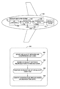
[0030] Referring to figure 1, there is illustrated an aircraft 100 comprising
an aircraft
ventilation system 102. The ventilation system 102 distributes low-pressure
air
throughout the interior of the aircraft 100, including a cabin, a flight deck,
aircraft
bays, and a cockpit. For simplicity, the interior of the aircraft 100 will be
referred to
herein as the cabin. Air supplied to the cabin consists mainly of outside air
from an
air compressor 104 and filtered, recirculated air via a recirculation system
106. The
air compressor 104 may comprise one or more main engines which supply bleed
air, i.e. compressed outside air. The air compressor 104 may also comprise one
or
more auxiliary power units (APU) supplying bleed air. In some embodiments, the
air compressor 104 comprises a combination of main engines and APUs which
together are used to supply bleed air for distribution into the cabin. In a
further
alternative, the air compressor 104 may be a dedicated air compressor that is
provided in order to supply fresh air to the cabin. In other embodiments, such
as
more electric aircraft applications, the bleed air may be supplied via
motorized
compressors.
[0031] A distribution system 108 receives compressed air from the air
compressor
104 and recirculated air from the recirculation system 106, and distributes
the air in
the cabin. The compressed and recirculated air may be combined at a defined or
- 6 -
CA 02985965 2017-11-14
WO 2016/189420 PCT/1B2016/052831
variable ratio before being distributed in the cabin. At least one first
sensor 110a is
provided between the air compressor 104 and the distribution system 108 to
monitor the air quality therebetween. At least one second sensor 110b is
provided
between the recirculation system 106 and the distribution system 108 to
monitor
the air quality therebetween. In an alternative embodiment, the second sensor
102b may be included as part of the recirculation system 106. Sensors 110a,
110b
may comprise an array of sensors for identifying concentration levels of
predefined
airborne contaminants possibly existing in the respective inlet air flows.
They may
be positioned anywhere along the air flow passages between the air sources
104,
106, and the cabin.
[0032] An air quality monitoring system 112 is connected to the aircraft
ventilation
system 102 for communication therewith. The air quality monitoring system 112
may receive from the sensors 110a, 110b concentration levels of targeted
volatile
organic compounds (VOCs) or other potential contaminants to the air in the air
flow
passages of the aircraft. The sensors 110a, 110b may thus be VOC sensors or
other air contaminant sensors, capable of detecting porn concentrations of
various
contaminants such as oxygen, carbon monoxide, carbon dioxide, nitrogen
dioxide,
sulfur dioxide, and particulate matter. For example, the sensors 110a, 110b,
may
be heating semiconductor, non-dispersive infrared, and/or light emitting diode
sensors; they may be based on micro-electro-mechanical systems (MEMS) and/or
wireless sensor network (WSN) technology. The sensors 110a, 110b may be
selected as a function of desired characteristics, such as size, accuracy,
power
consumption, and ability to detect one or more of the targeted air
contaminants.
[0033] The air quality monitoring system 112, upon receipt of sensor data, may
compare air contaminant concentration levels to one or more thresholds and
determine the need to advise a flight crew of an anomaly with regards to air
quality
in a given air flow passage. In some embodiments, an alert signal is triggered
when the air quality is found to be at an unacceptable level or at a level
that is
- 7 -
CA 02985965 2017-11-14
WO 2016/189420 PCT/1B2016/052831
below optimal. There may be a single level that triggers the alert, or there
may be
multiple levels. The alert signal may be transmitted to the crew via a
dedicated
graphical user interface (GUI) provided for the flight crew, namely the
pilot(s)
and/or flight attendants. For example; an indicator may be provided directly
on an
instrument panel in the cockpit or flight deck to signal a problem with the
air quality
in one of the air flow passages. Alternatively, the air quality monitoring
system 112
may interface with existing aircraft equipment, such as an Engine-Indication
and
Crew-Alerting System (EICAS) or other systems instrumentation, and the alert
signal may be displayed on a GUI of the existing aircraft equipment.
[0034] In some embodiments, the air quality monitoring system 112 is
configured to
determine, from the sensor data, a location within the aircraft ventilation
system
102 which may be the source of the air contaminant. For example, data received
from sensor 110a may indicate that the bleed air from the air compressor 104
is
unacceptably contaminated while data received from sensor 110b may indicate
that air provided by the recirculation system 106 is not contaminated beyond
acceptable limits. Other sensors may also be added within the aircraft
ventilation
system 102 in order to more specifically identify the source of the air
contamination
or a given air flow passage within the aircraft ventilation system 102. For
example,
another sensor 110c may be provided in an air flow passage between the cabin
and the recirculation system 106. The air quality monitoring system 112 may
therefore make a distinction between the quality of air entering the
recirculation
system 106 vs the quality of air exiting the recirculation system 106, thus
determining if the problem is within the recirculation system 106 itself. In
another
example, the air compressor 104 comprises a left engine and a right engine,
and
the sensors 110 are positioned to allow the air quality monitoring system 112
to
determine, from the sensor data, whether the source of the air contaminant is
the
left engine or the right engine. Comparison of sensor data form multiple
sensors
may be used to pinpoint the source of the problem.
- 8 -
CA 02985965 2017-11-14
WO 2016/189420 PCT/1B2016/052831
[0035] In some embodiments, the air quality monitoring system 112 may also
determine which corrective action may be taken in response to a determination
that
air quality in a given air flow passage comprises air contamination. For
example,
for ground operation, the air compressor 104 may be shut down and air
distribution
may rely only on the recirculation system 106 fitted with an advanced air
filter. This
corrective action may be used, for example, if it is determined that outside
air
passing through the air compressor 104 is contaminated, or that one of the
engines
has a contaminant emission. In one exemplary embodiment, this may occur when
the aircraft is sitting on a runway waiting for takeoff and is surrounded by
other
aircraft that generate exhaust fumes and thus contaminate the "fresh air"
source.
Alternatively, the recirculation system 106 may be shut down and air
distribution
may rely only on the air compressor 104. In some embodiments, the ratio of
compressed air to recirculated air may be varied to account for a reduced
quality in
any one of the air sources. Other examples of corrective actions are to
activate an
inactive air source or to recommend a maintenance (general or specific) to the
aircraft ventilation system 102.
[0036] In some embodiments, the air quality monitoring system 112 is
configured to
display the corrective action to be taken on a GUI to the flight crew.
Alternatively,
or in combination therewith, the air quality monitoring system 112 may be
configured to automatically apply the corrective action, depending on the
nature of
the corrective action. For example, a need for maintenance would simply be
displayed while a change in a ratio of compressed air to recirculated air may
be
performed automatically. The air quality monitoring system 112 may thus be
operatively connected to the aircraft ventilation system 102 for opening,
closing, or
regulating various inlet and outlet valves, shutting down and turning on air
sources
in the air compressor 104 or the recirculation system 106, and providing
command
signals to the distribution system 108 for control of air flow to the cabin.
Note that
the distribution system 108 may, in some embodiments, comprise air
conditioning
and/or flow control units. Control may be effected via command signals
transmitted
- 9 -
CA 02985965 2017-11-14
WO 2016/189420 PCT/1B2016/052831
through the existing aircraft wiring harnesses and cable assemblies, through
dedicated wiring/cabling, through a wireless network, or through a combination
thereof. The wireless network may operate using RE, infrared, VVi-Fi,
Bluetooth, or
other wireless technologies.
[0037] Figure 2a is a more detailed example of the aircraft ventilation system
102,
in accordance with one embodiment. In this example; the air compressor 104
comprises a left engine 204a, a right engine 204b, and an APU 206. Compressed
air from the left engine 204a and/or APU 206 flows through a left flow control
system 208a and a left air conditioning system 210a before reaching the
distribution system 108. Compressed air from the right engine 204b and/or APU
206 flows through a right flow control system 208b and a right air
conditioning
system 210b before reaching the distribution system 108. A plurality of
sensors
110d, 110e, 110f, 110g, 110h, 110j (collectively referred to as sensors 110)
are
provided throughout the system 102 for collecting sensor data and transmitting
the
sensor data to the air quality monitoring system 112.
[0038)A series of exemplary scenarios are illustrated in figures 2b to 2d. For
these
examples, the legend for reading sensor data is provided in table 1. The three
levels of air quality are for illustrative purposes. More or less air quality
levels may
be used.
No air flow ( M )
Acceptable level
Below optimal level
-10-
CA 02985965 2017-11-14
WO 2016/189420 PCT/1B2016/052831
Unacceptable level
'
TABLE 1
[0039] In figure 2b, the left and right engines 204a, 204b act as air sources
and the
recirculation system 106 is inactive. Sensor data from sensor 110d indicates
that
the left engine 204a has a contaminant emission. The air quality monitoring
and
control system 112 may recommend maintenance to the left engine 204a. Sensor
data from sensor 110F may also indicate that the left air conditioning system
210a
still has a contaminated air flow. The recirculation system 106 may be
activated to
compensate, together with the operational right engine 204b bleed system.
[0040] In figure 2c, the APU 206 acts as air source and the recirculation
system
106 is active. Sensor data from sensor 110j indicates that air from the
recirculation
system is contaminated at an unacceptable level. The air quality monitoring
system
112 may shut down the recirculation system 106 such that only air from the air
compressor 104 is circulated in the cabin via the distribution system 108. A
maintenance request may also be provided for the recirculation system 106.
[0041] In figure 2d, the left and right engines 204a, 204b act as air sources
and the
recirculation system 106 is active. Sensor data from sensors 110d, 110e. 110f,
110g indicate that external air coming through the air compressor 104 is
contaminated. Sensor data from sensor 110j also indicates that the air flowing
through the recirculation system 106 is below optimal level, likely due to the
contamination from the outside air mixed with the recirculated air before
being
distributed into the cabin. If this scenario occurs when the aircraft 100 is
on the
ground, the external air may be shutoff and recirculation may be increased.
This
corrective action can be verified as being effective when sensor 110j changes
to an
acceptable level.
-11 -
CA 02985965 2017-11-14
WO 2016/189420 PCT/1B2016/052831
[0042] The scenarios of figures 2b, 2c, and 2d illustrate examples of the
ability to
identify a potential problem, locate an origin of the problem within one of
the air
flow passages, and provide corrective actions as appropriate. Smells, odors,
smoke, and other contaminant events may occur while the aircraft is on the
ground
or in the air. The air quality monitoring system 112 may provide real time
airborne
contaminant monitoring and control, resulting in a reduction in costs and
potential
aircraft and occupant safety due to flight interruptions, flight delays,
misled
troubleshooting, component repairs, and air contamination exceedance.
Monitoring
the air quality in the various air flow passages may also allow a reduction to
specific fuel consumption (SFC) of the aircraft due to a reduction of external
air
(also known as "fresh" air) mass flow when possible.
[0043] In some embodiments, the air quality monitoring system 112 is also
configured for monitoring degradation of air quality in a particular air flow
passage
over time. This may allow the air quality monitoring system 112 to monitor
component performance and degradation trends of the aircraft ventilation
system
102, allowing for broad preventive maintenance actions to be scheduled. An
exemplary method is illustrated in the flowchart of figure 3. Method 300 is
for
monitoring air flow passage air quality. Steps 302, 304 represent sensing of
air
quality in multiple air flow passages between the ventilation system 102 and
the
cabin. These air flow passages may be between the air compressor 104 and the
distribution system 108 and between the recirculation system 106 and the
distribution system 108, as illustrated in figure 1. The air flow passages may
also
be the various passages illustrated in figure 2a. Other air flow passages for
other
aircraft ventilation system architectures may be monitored with sensors.
Strategically located sensors 110 will allow more precise diagnostics to be
provided. As per step 306, the degradation of air quality within the air flow
passages is monitored over time. This monitoring can take place over a single
flight or over a plurality of flights. For example, sensor data may be
gathered over
predetermined periods, such as weeks, months, or years, for analysis of trends
- 12-
CA 02985965 2017-11-14
WO 2016/189420 PCT/1B2016/052831
over the periods to assess the maintenance needs of the aircraft. As per step
308,
maintenance needs for the various components of the aircraft ventilation
system
102 are identified as a function of the degradation level of the air quality
within the
air flow passages over time.
[0044] Similarly to real-time monitoring and control, maintenance needs may be
displayed on a dedicated GUI or an existing aircraft display/equipment such as
the
EICAS. In addition, sensing data and/or air quality reports may be provided to
ground crew, using for example an Aircraft Communications Addressing and
Reporting System (AGARS) or other communication means with ground stations.
The air quality monitoring system 112 may interface with a cabin management
system (CMS) or a maintenance computer, for storing maintenance messages
showing degradation of air quality within the air flow passages or degradation
of
components of the ventilation system 102, indicating that a replacement is
needed
at a next aircraft maintenance check or earlier. Specific timelines for
performing
maintenance may be provided as a function of the degradation level. For
example,
degradation may be graded according to a scale, with a projected maintenance
timeline associated with each level of the scale. Table 2 illustrates an
exemplary
maintenance report.
Projected
1 Maintenance
Component i Degradation Level Maintenance
Task
Timeline
Recirculation
Replacement Level 4 Immediately
filter A
Recirculation
Replacement Level 1 12 months
filter B
Replace bearing,
Left engine Level 2 6 months
seal, gasket
APU Clean Level 3 3 months
,
-13-
CA 02985965 2017-11-14
WO 2016/189420 PCT/IB2016/052831
TABLE 2
[0045] More or less degradation levels may be used. Projected maintenance
timelines may also vary as a function of the component and how long it is
known to
take to further degrade. Some components may be graded using only two levels,
such as check or don't check, while others may be graded using a progressive
scale that is incremented as the component further degrades; or as the air
quality
sensed downstream from the component further degrades. In some embodiments,
air quality is directly correlated to degradation of a component and used to
assess
maintenance needs.
[0046] Referring to figure 4, there is illustrated an exemplary embodiment of
the air
quality monitoring system 112, which comprises, amongst other things; a
plurality
of applications 406a ... 406n running on a processor 404 coupled to a memory
402. It should be understood that while the applications 406a ... 406n
presented
herein are illustrated and described as separate entities, they may be
combined or
separated in a variety of ways.
[0047] The memory 402 accessible by the processor 404 may receive and store
data. The memory 402 may be a main memory, such as a high speed Random
Access Memory (RAM), or an auxiliary storage unit, such as a hard disk, a
floppy
disk, or a magnetic tape drive. The memory 402 may be any other type of
memory,
such as a Read-Only Memory (ROM), or optical storage media such as a videodisc
and a compact disc. The memory 402 illustratively has stored therein any one
of
sensor data, corrective actions; degradation levels, performance trends,
maintenance schedules, and grading scales.
[0048] The processor 404 may access the memory 402 to retrieve data. The
processor 404 may be any device that can perform operations on data. Examples
are a central processing unit (CPU); a front-end processor, a microprocessor,
and
- 14-
CA 02985965 2017-11-14
WO 2016/189420 PCT/1B2016/052831
a network processor. The applications 406a ... 406n are coupled to the
processor
404 and configured to perform various tasks.
[0049] In some embodiments, the air quality monitoring system 112 is a
downloaded software application, a firmware application, or a combination
thereof
on an existing aircraft system. Alternatively, dedicated hardware is provided
for the
air quality monitoring system 112 and connected to the aircraft for
communication
with the sensors 110, the aircraft ventilation system 102, and any other
equipment
and/or system onboard with which it is to interface. In some embodiments, the
air
quality monitoring system 112 is remotely accessible via a device such as a
personal computer, a tablet, a smartphone, or the like, via a wired or
wireless
connection. In some embodiments, the air quality monitoring system 112 may
itself
be provided directly on one of the devices, either as a downloaded software
application, a firmware application, or a combination thereof.
[0050] Figure 5 is an exemplary embodiment of an application 406a running on
the
processor 404. The application 406a illustratively comprises a sensor data
module
502 and an air quality diagnostic module 504. The sensor data module 502 is
configured to receive sensor data from all of the sensors 110 provided
throughout
the aircraft ventilation system 102. It may be configured to sort through the
sensor
data in order to identify a location from which the sensor data is received.
Sensor
data may be received with identification data in order to determine the sensor
from
which the data is received. The air quality diagnostic module is configured to
determine, based on the sensor data, air quality for individual air flow
passages of
the aircraft ventilation system 102.
[0051] As per figure 6, the air quality diagnostic module 504 may be separated
into
a real time monitoring module 602 and a performance and degradation module
604. Some embodiments may comprise only one of these two modules 602, 604.
The real time monitoring module 602 may be configured to perform air quality
monitoring in real time, in any one of a passive, an active, and an active
control
-15-
CA 02985965 2017-11-14
WO 2016/189420 PCT/1B2016/052831
mode. In passive mode, the real time monitoring module 602 may trigger an
alert
signal if any concentration level of the sensed air flow passages are above or
below a given threshold. The alert signal may comprise a location for the
possible
contamination within the aircraft 100. In active mode, the real time
monitoring
module 602 may provide a recommended corrective action or operational task to
address detected concentration levels above or below given thresholds. The
recommended corrective actions may be displayed for the flight crew as soon as
the issue is detected. In active control mode, the real time monitoring module
602
may automatically perform some of the corrective actions, such as shutting
down
one or more air source, activating one or more air source, and varying a ratio
of
conditioned air to recirculated air that is distributed within the aircraft
cabin.
[0052] The performance and degradation module 604 may be coupled to the real
time monitoring module 602, for example for receiving sensor data and/or
concentration measurements therefrom, or it may operate independently. It may
be
configured for monitoring degradation of the air quality over time based on
the
sensor data, and for identifying one or more maintenance needs for the various
components in the aircraft ventilation system 102 as a function of the
degradation
level of the air quality.
[0053] It will be understood that the real time monitoring module 602 and the
performance and degradation module 604 may be provided as a single module
that can perform both real time monitoring and performance and degradation
assessments. Similarly, these two functions may be provided in separate
applications 406a, 406n, that run separately on the processor 404. Also
alternatively, the two functions may be provided in separate applications that
run
on separate processors. Other alternative configurations for the
software/hardware
architecture of the air quality monitoring system 112 will be readily
understood by
those skilled in the art. The above description is meant to be exemplary only,
and
one skilled in the relevant arts will recognize that changes may be made to
the
-16-
CA 02985965 2017-11-14
WO 2016/189420 PCT/1B2016/052831
embodiments described without departing from the scope of the invention
disclosed. For example, the blocks and/or operations in the flowcharts and
drawings described herein are for purposes of example only. There may be many
variations to these blocks and/or operations without departing from the
teachings of
the present disclosure. For instance, the blocks may be performed in a
differing
order, or blocks may be added, deleted, or modified.
[0054] While illustrated in the block diagrams as groups of discrete
components
communicating with each other via distinct data signal connections, it will be
understood by those skilled in the art that the present embodiments are
provided
by a combination of hardware and software components, with some components
being implemented by a given function or operation of a hardware or software
system, and many of the data paths illustrated being implemented by data
communication within a computer application or operating system. The structure
illustrated is thus provided for efficiency of teaching the present
embodiment. The
present disclosure may be embodied in other specific forms without departing
from
the subject matter of the claims. Also, one skilled in the relevant arts will
appreciate
that while the systems, methods and computer readable mediums disclosed and
shown herein may comprise a specific number of elements/components, the
systems, methods and computer readable mediums may be modified to include
additional or fewer of such elements/components. The present disclosure is
also
intended to cover and embrace all suitable changes in technology.
Modifications
which fall within the scope of the present invention will be apparent to those
skilled
in the art, in light of a review of this disclosure, and such modifications
are intended
to fall within the appended claims.
- 17-