Note: Descriptions are shown in the official language in which they were submitted.
DEVICES AND METHODS FOR OCCLUSION OF AN ATRIAL APPENDAGE
CROSS-REFERENCE TO RELATED APPLICATION
[0001] This application claims priority to Provisional Application No.
62/161,742, filed May 14, 2015.
TECHNICAL FIELD
[0001] The present disclosure relates to implantable medical devices that may
be
used to occlude apertures, conduits, spaces, organs, and other structures
within a
patient.
BACKGROUND
[0002] Cardiac structures such as atrial appendages can contribute to cardiac
blood
flow disturbance, which is associated with a number of cardiac-related
pathologies.
For example, complications caused by blood flow disturbance within an
appendage
and associated with atrial fibrillation can contribute to embolic stroke.
SUMMARY
[0004] Various aspects of the present disclosure provide implantable medical
devices that may be used to occlude apertures, conduits, space, organs and
other
structures within a patient, including structures within the heart. For
example, this
disclosure provides occlusion devices that can be deployed into a patient.
Deployment may occur using transcatheter techniques, although various
deployment
techniques are contemplated.
[0005] The devices, consistent with various aspects of the present disclosure
may
be deployed into an atrial appendage of the patient. The heart has left and
right
atrial appendages. Various aspects of the present disclosure are directed
toward
occlusive devices that provide enhanced conformability of a frame of the
device
(including the occlusive face) relative to the atrial appendage walls under
1
CA 2986047 2019-04-03
CA 02986047 2017-11-10
WO 2016/183495 PCT/1JS2016/032487
physiological conditions. In addition, the present disclosure is directed
toward
occlusive devices that may provide more complete and rapid closure of the
appendages including improved sealing of the appendages around the ostium
thereof, enhanced clinical outcomes including reduced thrombus formation,
reduced
occluder embolization, greater conformability, and enhanced clinical ease-of-
use,
patient safety, and overall efficacy.
[0006] Various aspects of the present disclosure are directed toward
apparatuses,
methods, and systems as relating to occlusion. In certain embodiments, devices
for
placement in vessels, appendages, and openings in a body may include a unitary
self-expanding frame having a proximal end, a distal end, and a longitudinal
axis. In
certain embodiments, the unitary self-expanding frame may include a face
portion
having a pre-loaded flat configuration and (i) a center frame portion arranged
at the
proximal end and (ii) a plurality of elongate members extending from the
center
frame portion, and a body portion. In certain embodiments, devices may include
a
membrane attached to the unitary self-expanding frame. In certain embodiments,
the
plurality of elongate members may be configured to bend or flex substantially
in a
plane orthogonal to the longitudinal axis and mitigate longitudinal movement
of the
face portion in response to a compressive force applied to the body portion of
the
unitary self-expanding frame.
[0007] In certain embodiments, devices for placement in vessels, appendages,
and
openings in a body having an elongated configuration and a deployed
configuration
may include a nitinol cut-tube frame having a proximal end and a distal end.
In
certain embodiments, the nitinol cut-tube frame may include a face portion
having a
center frame portion arranged at the proximal end and including a plurality of
arcs
arranged around a circumference of the center frame portion, and a plurality
of
elongate members extending from the center frame portion, and a body portion.
In
certain instances, the devices may also include a membrane attached to the
nitinol
cut-tube frame. In addition and in certain instances, the center frame portion
and the
plurality of elongate members may form a substantially uniform surface, and
the
center frame portion may be configured to provide an attachment point for a
delivery
system for the device.
2
CA 02986047 2017-11-10
WO 2016/183495 PCMJS2016/032487
[0008] In certain embodiments, methods of reducing thrombus formation in
treatment of left atrial appendage of a patient may include positioning a
transcatheter
assembly through an ostium of the left atrial appendage. In certain
embodiments,
the methods may also include deploying a device from the transcatheter
assembly,
the device comprising: a unitary self-expanding frame having a proximal end, a
distal
end, and a longitudinal axis, the unitary self-expanding frame including a
face portion
having a center frame portion arranged at the proximal end and a plurality of
elongate members extending from the center frame portion, a body portion
arranged
substantially orthogonal to the face portion, and a membrane attached to the
unitary
self-expanding frame, wherein the face portion and the membrane define an
occlusive face of the device. In addition and in certain embodiments, the
methods
may include absorbing one or more forces from the left atrial appendage with
thereby flexing the plurality of elongate members in a plane orthogonal to the
longitudinal axis to mitigate longitudinal movement of the face portion in
response
thereto.
[0009] While multiple embodiments are disclosed, still other embodiments of
the
present disclosure will become apparent to those skilled in the art from the
following
detailed description, which shows and describes illustrative embodiments of
the
disclosure. Accordingly, the drawings and detailed description are to be
regarded as
illustrative in nature and not restrictive.
BRIEF DESCRIPTION OF THE DRAWINGS
[0010] FIG. 1A is a cross-sectional view of a human heart in which a delivery
system is positioned in preparation for deployment of an occlusive device into
a LAA
of the heart, in accordance with various aspects of the present disclosure.
[0011] FIG. 1B shows the configuration of FIG. 1A with the occlusive device
deployed from the delivery system and positioned within the LAA, in accordance
with
various aspects of the present disclosure.
[0012] FIG. 1C shows the configuration of FIG. 1A with the occlusive device
deployed from the delivery system and positioned within a vessel, in
accordance with
various aspects of the present disclosure.
3
CA 02986047 2017-11-10
WO 2016/183495 PCMJS2016/032487
[0013] FIG. 2 is a perspective view of an example frame for an occlusive
device, in
accordance with various aspects of the present disclosure.
[0014] FIG. 3 is a top view of an illustration of an example face portion of
an
occlusive device, in accordance with various aspects of the present
disclosure.
[0015] FIG. 4A is a schematic representation of a top view of an example face
portion of an occlusive device in a first configuration prior to a force being
applied, in
accordance with various aspects of the present disclosure.
[0016] FIG. 4B is a top view of an illustration of the example face portion,
shown in
FIG. 4A, in a second configuration in response to the force being applied, in
accordance with various aspects of the present disclosure.
[0017] FIG. 5A is a side view of an illustration of another example frame of
an
occlusive device, in accordance with various aspects of the present
disclosure.
[0018] FIG. 5B is a side view of the example frame of an occlusive device with
a
curvature in the face portion, in accordance with various aspects of the
present
disclosure.
[0019] FIG. 6A is a top view of an illustration of a portion of an example
frame and
center frame portion that may be included with an occlusive device, in
accordance
with various aspects of the present disclosure.
[0020] FIG. 6B is a perspective view of the example frame and center frame
portion
shown in FIG. 6A, prior to flattening and similar to the as-loaded condition
in the
delivery system in accordance with various aspects of the present disclosure.
[0021] FIG. 7 is a perspective view of an example occlusive device, in
accordance
with various aspects of the present disclosure.
[0022] FIG. 8 is a perspective view of another example frame for an occlusive
device, in accordance with various aspects of the present disclosure.
[0023] FIG. 9A is a perspective view of another example frame for an occlusive
device in a shape set configuration, in accordance with various aspects of the
present disclosure.
4
CA 02986047 2017-11-10
WO 2016/183495 PCT/1JS2016/032487
[0024] FIG. 9B is a side view of a strut cut pattern of the frame, shown in
FIG. 9A,
prior to deformation to the shape set configuration, in accordance with
various
aspects of the present disclosure.
[0025] FIG. 10 is example flat pattern that can be used for forming a sheet
material
to create a frame of an occlusive device, in accordance with various aspects
of the
present disclosure.
[0026] FIG. 11 is another example flat pattern that can be used for forming a
sheet
material to create a frame of an occlusive device, in accordance with various
aspects
of the present disclosure.
[0027] FIG. 12 is a top view of an example center frame portion that may be
included with an occlusive device, in accordance with various aspects of the
present
disclosure.
[0028] FIG. 13 is a perspective view of an alternate design of an example
frame for
an occlusive device, in accordance with various aspects of the present
disclosure.
[0029] FIG. 14 is a perspective view of an alternate design of another example
frame for an occlusive device, in accordance with various aspects of the
present
disclosure.
[0030] FIG. 15 is a perspective view of an alternate design of another example
frame for an occlusive device, in accordance with various aspects of the
present
disclosure.
[0031] FIG. 16 is a perspective view of an alternate design of another example
frame for an occlusive device, in accordance with various aspects of the
present
disclosure.
[0032] FIG. 17 is a perspective view of an alternate design of another example
frame for an occlusive device, in accordance with various aspects of the
present
disclosure.
[0033] FIG. 18 is a perspective view of an alternate design of another example
frame for an occlusive device, in accordance with various aspects of the
present
disclosure.
CA 02986047 2017-11-10
WO 2016/183495 PCMJS2016/032487
[0034] While the disclosure is amenable to various modifications and
alternative
forms, specific embodiments have been shown by way of example in the drawings
and are described in detail below. The intention, however, is not to limit the
disclosure to the particular embodiments described. On the contrary, the
disclosure
is intended to cover all modifications, equivalents, and alternatives falling
within the
scope of the disclosure as defined by the appended claims.
DETAILED DESCRIPTION
[0035] FIGs. 1A-B are a cross-sectional views of a human heart 10 in which a
delivery system 20 is positioned in preparation for deployment of an occlusive
device
30 into an appendage 18 of the heart, in accordance with various aspects of
the
present disclosure. FIGs. 1A-B show a depiction of includes a right atrium 14,
a left
atrium 16, a right ventricle 32, and a left ventricle 34 of the heart 10. As
is shown,
the appendage 18 is located in the left atrium 16 of the heart 10, and thus,
the
appendage 18 may be considered the left atrial appendage 18. Although the
following discussion focuses on deployment of the occlusive device 30 into the
left
atrial appendage 18, the occlusive device 30 may be deployed in other
appendages
or openings within the human heart 10 or in other locations of the human body.
[0036] The left atrial appendage 18 may be considered a muscular pouch
extending
from the anterolateral wall 36 of the left atrium 16 of the heart 10, which
serves as a
reservoir for the left atrium 16. In a normal cardiac cycle, the left atrial
appendage
18 may contract rhythmically with the rest of the left atrium 16 during
contraction of
the heart 10. Thus, during a normal cardiac cycle, the left atrial appendage
18
contracts with the left atrium 16 and pumps blood that may gather or collect
within
the left atrial appendage 18 to circulate therefrom. However, during cardiac
cycles
characterized by arrhythmias (e.g., atrial fibrillation), the left atrial
appendage 18 may
fail to sufficiently contract along with the left atrium 16, which can allow
blood to
stagnate within the left atrial appendage 18. Stagnant blood within the atrial
appendage 18 is susceptible to coagulating and forming a thrombus, which can
dislodge from the atrial appendage 18 and ultimately result in an embolic
stroke. The
occlusive device 30, consistent with various aspects of the present
disclosure, may
6
CA 02986047 2017-11-10
WO 2016/183495 PCMJS2016/032487
be delivered to the left atrial appendage 18 to help prevent and militate
against blood
stagnation within the left atrial appendage 18.
[0037] In certain instances and as is shown in FIGs.1A-B, the occlusive device
30
may be delivered to the left atrial appendage 18 by way of a minimally
invasive
transcatheter procedure. More specifically, the delivery system 20 may be
navigated
through a vena cava 12, into the right atrium 14, through an atrial septum 15,
and
into the left atrium 16 towards the appendage 18. In some implementations, the
percutaneous access to the patient's vasculature can be at the patient's
femoral
vein, for example. It should be understood that this example technique is
merely one
example, and many other access techniques can also be performed to deploy the
occlusive devices provided herein. At this point of the deployment process,
the
occlusive device is contained within a lumen of the delivery system 20, and is
configured in a collapsed low-profile delivery configuration. Although
transcatheter
systems are generally shown and described, other delivery systems (e.g.,
thoracoscopic) are also contemplated.
[0038] FIG. 1B shows the configuration of FIG. 1A with the occlusive device 30
deployed from the delivery system 20 and positioned within the left atrial
appendage
18, in accordance with various aspects of the present disclosure. As shown, a
control catheter 22 may releasably couple to the occlusive device 30, and is
slidably
disposed within the lumen of the delivery system 20. The control catheter 22
can be
used by a clinician operator to make the occlusive device 30 deploy from the
delivery
system 20. For example, after positioning the occlusive device 30 through an
ostium
38 of the left atrial appendage 18, the clinician operator can retract the
delivery
system 20 in relation to the control catheter 22 to unsheath and deploy the
occlusive
device 30. The ostium 38 may be considered a portion of the anterolateral wall
36 of
the left atrium 16 from which a taper originates to form the pouch-like
structure of the
left atrial appendage 18. The occlusive device 30 may include an occlusive
face 40
that is arranged near the ostium 38 of the left atrial appendage 18. As
discussed in
further detail below (e.g., with reference to FIG. 6A-B), the control catheter
22 may
releasably couple to the occlusive device 30 via a hub or center frame portion
or a
plug (or the like) inserted into the center frame portion arranged centrally
within the
occlusive face 40 of the occlusive device 300.
7
CA 02986047 2017-11-10
WO 2016/183495 PCT/1JS2016/032487
[0039] After emerging from the constraining confines of the delivery system
20, the
occlusive device 30 can reconfigure to an expanded configuration. The
occlusive
device 30 may expand to conform to the contours of the space defined within
the left
atrial appendage 18. In certain instances, positioning of the occlusive device
30
relative to the ostium 38 of the left atrial appendage 18 may be enhanced and
ensures that the occlusive device 30 prevents thrombus from embolizing from
the left
atrial appendage 18. More specifically, the occlusive face 40 may be arranged
within the left atrial appendage 18 such that the occlusive face 40 connects
portions
of the anterolateral wall 36 on opposite sides of the ostium 38 to form a
substantially
uniform surface. In certain instances, blood may collect or stagnate along the
face of
a device implanted therein if the occlusive face is non-uniform (e.g., a
device having
a hub that protrudes beyond other portions of the occlusive face; a device
having a
occlusive face that is concave, partially concave, or includes depressions, a
device
having a occlusive face that is concave, partially concave, or includes
depressions
and a covering attached thereto that may drape or wrinkle as a result of the
non-
uniform face) relative to the ostium 38 of the left atrial appendage 18 or the
occlusive
face includes protuberances. In these instances, thrombus may occur along the
face
of the occlusive device as a non-uniform surface may alter/disrupt the blood
flow
within the left atrium 18. Thus, a patient may remain susceptible to blood
coagulation and thrombus formation if an occlusive device includes a non-
uniform
surface as the result of improper positioning or the design of the device.
[0040] After proper positioning and delivery of the occlusive device 30, the
control
catheter 22 can be decoupled from the occlusive device 30, and the delivery
system
20 and control catheter 22 can be removed from the patient. With the occlusive
device 30 deployed as shown, the space defined within the left atrial
appendage 18
is essentially separated from the left atrium 16 by virtue of the physical
barrier
provided by the occlusive device 30. In this manner, stagnant blood within the
LAA
18 that is susceptible to coagulating and forming thrombi may be prevented
from
entering the left atrium 16, and thereby prevented from potentially causing an
embolic stroke. In addition, positioning of the occlusive face 40 of the
occlusive
device 30 relative to the ostium 38 of the left atrial appendage 18 may help
prevent
blood collecting or stagnating along the face of the occlusive device 30.
8
CA 02986047 2017-11-10
WO 2016/183495 PCMJS2016/032487
[0041] As noted above, the occlusive devices provided herein can be used in
many
different areas of the body, and that deployment of the occlusive device 30
into the
left atrial appendage 18 is merely one example implementation. More
specifically,
FIG. 1C shows the configuration of FIG. 1A with the occlusive device 30
deployed
from the delivery system and positioned within a vessel between the vessel
walls 42,
in accordance with various aspects of the present disclosure.
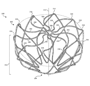
[0042] FIG. 2 is a perspective view of an example frame 200 for an occlusive
device. As shown, the frame 200 may include a proximal end 202 and a distal
end
204, and may be unitary and self-expanding. In addition, the frame 200 may
include
a plurality of elongate members 206 and a center frame portion 208 arranged at
the
proximal end 202 of the frame 200. The plurality of elongate members 206 may
extend from the center frame portion 208. Together, the combination of the
plurality
of elongate members 206 and the center frame portion 208 form a face portion
220.
In addition, the frame 200 may include a body portion 214. The frame 200,
including
the plurality of elongate members 206 and the center frame portion 208, is
shown in
a pre-loaded flat configuration. In certain instances and as discussed in
further detail
relative to FIGs. 5A-B, the frame 200 may be slightly bowed as a result of
being
loaded into and deployed from a delivery system. In the pre-loaded flat
configuration
and as shown, the plurality of elongate members 206 and the center frame
portion
208 (the face portion 220) form a substantially planar surface (e.g., between
0 mm
and 1 mm outward deflection measured from transition portions 216). In certain
instances, the center frame portion 208 is a hole having an inner and outer
circumference and a plurality of elongate members 206 radiate outward from the
outer circumference of the center frame portion 208.
[0043] The face portion 220 may be formed by the center frame portion 208 and
plurality of elongate members 206. A boundary of the face portion 220 may be
considered to be at transition portions 216 of the frame 200. As shown, the
transition portions 216 are arranged around a periphery of the face portion
220. The
transition portions 216 transition the frame 200 between the plurality of
elongate
members 206 and the body portion 214 are external to the face portion 220.
More
specifically, the body portion 214 of the frame 200 extends from the plurality
of
elongate members 206, and the transition portions 216 transitions the
plurality of
9
CA 02986047 2017-11-10
WO 2016/183495 PCT/1JS2016/032487
elongate members 206 of the frame 200 to the body portion 214 of the frame
200.
As discussed in further detail below and in certain embodiments, transition
portions
216 may be configured as a landing zone that contact the walls of the
appendage or
vessel into which the frame 200 (as part of an occlusive device) is implanted.
The
transition portions 216 may enhance conformability of the frame 200 relative
to the
walls of the appendage or vessel.
[0044] The body portion 214 may include any number of rows and cells. The body
portion 214 may bifurcate to form multiple cells in a row, or the body portion
214 may
extend directly to the distal end 204 of the frame. In certain embodiments,
the body
portion 214 may include cells formed of a five-sided shape, a six-sided shape,
or
other shapes such as, but not limited to, polygonal, square, rectangular,
parallelogram-shaped, rhomboidal, trapezoidal, diamond-shaped, chevron-shaped,
octagonal, triangular, and the like. Different shapes and arrangements of the
body
portion 214 are shown, for example, in FIGs. 13-18.
[0045] In certain instances, the plurality of elongate members 206 are
configured to
flex and mitigate longitudinal movement (relative to a longitudinal axis 212
of the
frame 200) of the face portion 220 in response to a compressive force applied
to the
body portion 214 of the frame 200. In some embodiments, the force is applied
to the
transition portions 216. The plurality of elongate members 206 may enhance
fatigue
resistance of the frame 200 by functioning as stress relief features that
absorb
flexure and/or torque, and the like, in response to one or more forces being
applied
to the frame 200. In certain instances and as disused in further detail below
with
respect to FIGs. 5A-B, the plurality of elongate members 206 configured to
mitigate
movement of the face portion 220 substantially outward from the plane, and
movement outward from the plane may include outward deflection of the face
portion
220.
[0046] As shown, the face portion 220 is a substantially uniform (proximal)
surface
formed by the plurality of elongate members 206 and the center frame portion
208.
The plurality of elongate members 206 and the center frame portion 208 may
include
an equal and constant surface across the face portion 220. In addition, the
plurality
of elongate members 206 and the center frame portion 208 may be formed without
protrusions outward from the face portion 220. In certain instances, the
plurality of
CA 02986047 2017-11-10
WO 2016/183495 PCT/1JS2016/032487
elongate members 206 and the center frame portion 208 may include
approximately
equal thickness (relative to the longitudinal axis 212) across the face
portion 220. As
discussed in further detail below, the face portion 220 having a substantially
uniform
surface or a surface without protrusions outward therefrom may enhance
performance of an occlusive device that includes the frame 200 by mitigating
the
opportunity for thrombus formation. In certain instances, the substantially
uniform
surface of the face portion 220 may be planar.
[0047] As noted above, the plurality of elongate members 206 are configured to
bend or flex substantially in a plane (formed by the face portion 220)
orthogonal to
the longitudinal axis 212 to mitigate longitudinal movement (relative to the
longitudinal axis 212 of the frame 200) of the face portion 220 in response to
a
compressive force applied to the body portion 214 of the frame 200. The force
may
be considered a compressive force, and the compressive force may be applied to
one or more locations on the body portion 214 of the frame 200. In certain
instances, the compressive force may be non-uniform relative to the frame 200,
and
in other instances the force may be considered a radial force, which may be
defined
as a force, or a component of a force, that is directed inwardly from one or
more
locations relative to the frame 200. In all or any of these instances, the
force applied
to one or more locations on the body portion 214 is directed along the body
portion
214 toward the plurality of elongate members 206. The plurality of elongate
members 206 may absorb the applied force(s), and balance and/or share the
applied
force(s) throughout the frame 200. As a result, the plurality of elongate
members
206 bend or flex substantially in the plane orthogonal to the longitudinal
axis 212 to
mitigate movement of the face portion 220 (the combination of the plurality of
elongate members 206 and the center frame portion 208) relative to the
longitudinal
axis 212 in response to a force applied to the frame 200. In addition and in
certain
instances, the plurality of elongate members 206 flex and mitigate movement of
the
face portion 220 independent of the shape or arrangement of the body portion
214 of
the frame 200.
[0048] Mitigating movement of the face portion 220 of the frame 200 may
enhance
performance of the frame 200 when implanted in a vessel or opening in a body.
More specifically, when the frame 200 (or an occlusive device that includes
the
11
CA 02986047 2017-11-10
WO 2016/183495 PCT/1JS2016/032487
frame 200) is positioned within, for example, the contours of the space
defined within
a left atrial appendage (e.g., left atrial appendage 18 shown in FIGs. 1A-B or
within a
vessel as shown in FIG. 1C), thrombosis may occur along an occlusive device in
instances where a non-uniform surface alters a blood flow across the face of
the
device. Mitigating movement of the face portion 220 longitudinally decreases
the
opportunity for thrombus formation by avoiding disruption of the blood flow.
In
addition, the face portion 220 having a substantially uniform surface or a
surface
without protrusions outward therefrom similarly enhances performance by
avoiding
disruption of the blood flow. In addition, occlusive devices having an
occlusive face
with depressions (e.g., curvature of at least a portion of the occlusive face
inwardly)
may not only disrupt blood flow by allowing blood to pool along the occlusive
face but
blood may collect within the depressions. Each of these instances may
contribute to
thrombus formation. In certain instances, such a device that includes
depressions in
the occlusive face may utilize a membrane to attempt to provide a uniform
surface.
The membrane may dip within the depression or wrinkle as a result of the non-
uniform surface, and therefore disrupt blood flow across the occlusive face.
Thus,
the frame 200 including a uniform face portion 220 and also mitigating against
movement of the face portion 220 in response to forces applied to the frame
200
may enhance performance of an occlusive device that includes the frame 200 by
mitigating the opportunity for thrombus formation.
[0049] In addition, the plurality of elongate members 206 being configured to
flex
and mitigate movement of the face portion 220 longitudinally relative to the
longitudinal axis 212 may enhance the conformability of the frame 200. More
specifically, the plurality of elongate members 206 may facilitate the ability
of the
frame 200, and more particularly the body portion 214, to conform to irregular
tissue
topographies and/or dynamically variable tissue topographies. When the frame
200
is implanted into variable tissue topography, force applied from the tissue
topography
may be directed to one or more locations on the body portion 214 and/or the
transition portions 216. In certain instances, this force is directed along a
length of
the body portion 214 toward the plurality of elongate members 206, and the
plurality
of elongate members 206 absorb the applied force(s), and balance and/or share
the
applied force(s) throughout the frame 200. As a result, portions of the frame
200 that
contact the variable tissue topography may conform thereto (as opposed to a
frame
12
CA 02986047 2017-11-10
WO 2016/183495 PCMJS2016/032487
forcing the variable tissue topography to conform to the shape of the frame).
In
addition, the transition portions 216 of the frame 200 may conform to the
shape of an
ostium when implanted. In certain instances, the frame 200 (which may include
a
membrane attached thereto) may be positioned within a left atrial appendage to
help
prevent thrombus from embolizing from the left atrial appendage (e.g., as
shown
above in FIG. 1B). After implantation, portions of the frame 200 that contact
the left
atrial appendage conform thereto, and forces that are applied via the left
atrial
appendage may be absorbed by the plurality of elongate members 206. Under
physiological conditions of the heart the plurality of elongate members 206
are
configured to maintain the face portion 220 on opposite sides of an ostium of
the left
atrial appendage to form and maintain a substantially uniform surface closing
off the
ostium while allowing the transition portions 216 and portions of the body
portion 214
that contact the appendage are configured to conform to the shape of the
appendage.
[0050] Such conformability characteristics can be advantageous for providing
substantial occlusion (sealing) and durable occlusion. Conformability can also
enhance the fatigue resistance of the occlusive devices. Further, occlusive
devices
with substantial conformability are less traumatic to the patient and may tend
to
resist in situ migration better than occlusive devices with less
conformability. In
some embodiments of the occlusive devices provided herein, some portions of
the
devices are designed to be more conformable than other portions of the same
device. That is, the conformability of a single occlusive device can be
designed to
be different at various areas of the device. Additionally, in some embodiments
frame
material selection, heat treatments and other treatments can be used to attain
a
desired extent of conformability. In certain instances, the frame 200 may be
formed
from nitinol (NiTi). In certain more specific embodiments, the frame 200 may
be
formed from a single unitary piece of nitinol.
[0051] To deliver the frame 200 to locations within the body, the frame 200
may be
reconfigured to a low-profile (elongated) configuration for loading into a
delivery
catheter (e.g., such as the control catheter 22 shown in FIGS. 1-B) used for
transcatheter deployment of the occlusive device. After emerging from the
constraining confines of a delivery system, the frame 200 is configured to
self-
13
CA 02986047 2017-11-10
WO 2016/183495 PCMJS2016/032487
expand and reconfigure to the configuration shown in FIG. 2. The frame 200,
for
example, may be expanded to conform to the contours of the space defined
within
the body (e.g., left atrial appendage 18 shown in FIGs. 1A-B or within a
vessel as
shown in FIG. 1C). As noted above, the center frame portion 208 may serve as
the
connection point to a control catheter for transcatheter deployment of the
occlusive
device. As a result, the frame 200 (and the occlusive device that includes the
frame
200) may have a face portion 220 that is hubless (e.g., no addition structure
or
element beyond that of the center frame portion 208, lacking in additional
thickness
beyond that of the center frame portion 208, rimless, or lacking in dimension
beyond
a maximum thickness of the plurality of elongate members 206 and the center
frame
portion 208). The face portion 220 lacking a hub (e.g., such as any eyelet
that
extends beyond the face portion 220) provides for an approximately uniform
surface
formed by the plurality of elongate members 206 and the center frame portion
208.
[0052] The illustrative components shown in FIG. 2 are not intended to suggest
any
limitation as to the scope of use or functionality of embodiments of the
disclosed
subject matter. Neither should the illustrative components be interpreted as
having
any dependency or requirement related to any single component or combination
of
components illustrated therein. Additionally, any one or more of the
components
depicted in any of the FIG. 2 may be, in embodiments, integrated with various
other
components depicted therein (and/or components not illustrated), all of which
are
considered to be within the ambit of the disclosed subject matter. For
example, the
frame 200 described with reference to FIG. 2 may be used in connection with
delivery system 20 (shown in FIGs. 1A-B). More specifically, the frame 200 may
form a portion of occlusive device 30 (e.g., with the plurality of elongate
members
206 and the center frame portion 208 forming a portion of the occlusive face
40). In
addition, the frame 200 may include a membrane attached thereto (e.g., as
shown
and discussed with reference to FIG. 7).
[0053] FIG. 3 is a top view of an illustration of an example face portion 300
of an
occlusive device, in accordance with various aspects of the present
disclosure. The
face portion 300 includes a plurality of elongate members 302 and a center
frame
portion 304. As shown, the plurality of elongate members 302 may extend from
the
center frame portion 304 and include a common curvature within the face
portion
14
CA 02986047 2017-11-10
WO 2016/183495 PCMJS2016/032487
300, which is formed substantially within a common plane (e.g., the x-y plane,
as
shown). The common curvature may provide for the plurality of elongate members
302 to be non-overlapping within the face portion 300. In certain instances,
the
plurality of elongate members 302 may have a zig-zag pattern (e.g., as shown
in
FIG. 8).
[0054] The plurality of elongate members 302 may include any number of
curvature
or semi-curved patterns. Other curvature patterns are shown, for example, in
FIGs.
8-11. As shown, each of the plurality of elongate members 302 includes
multiple
curved sections. For illustrative purposes, the curved sections are
highlighted for
one of the plurality of elongate members 302 in FIG. 3. The plurality of
elongate
members 302 may include a first curved section 306, a second curved section
308,
and a third curved section 310. In certain instances, the first curved section
306 and
the third curved section 310 are curved in a first direction, and the second
curved
section 308 is curved in a second direction that is opposite that of the first
direction.
As a result, the plurality of elongate members 302 may include a first
inflection point
318 between the first curved section 306 and the second curved section 308,
and a
second inflection point 320 between the second curved section 308 and the
third
curved section 310. The first inflection point 318 and the second inflection
point 320
alter the curvature of the plurality of elongate members 302.
[0055] In addition, each of the first curved section 306, the second curved
section
308, and the third curved section 310 are arranged within the common plane.
Thus,
the plurality of elongate members 302, and the curvature formed by the first
curved
section 306, the second curved section 308, and the third curved section 310
occurs
substantially within the x-y plane. More specifically, each of the first
curved section
306, the second curved section 308, and the third curved section 310 are
curved
within the x-y plane. The center frame portion 304 may also be arranged with
the x-y
plane. When the face portion 300 is included with an occlusive device, the
plurality
of elongate members 302 and the center frame portion 304 may be arranged
within
a common plane. In addition and when the face portion 300 is included with an
occlusive device, the plurality of elongate members 302 are configured to flex
and
mitigate longitudinal movement (orthogonal to the x-y plane) of the face
portion 300
in response to a compressive force applied to another portion of the occlusive
device
CA 02986047 2017-11-10
WO 2016/183495 PCT/1JS2016/032487
(e.g., as discussed above in detail with reference to FIG. 2.). The plurality
of
elongate members 302 are configured to flex or bend substantially within the x-
y
plane to mitigate longitudinal movement (orthogonal to the x-y plane) of the
face
portion 300.
[0056] In certain instances, each of the first curved section 306, the second
curved
section 308, and the third curved section 310 may include equal radiuses of
curvature. In other instances, the first curved section 306 and the third
curved
section 310 may include a first radius of curvature, the second curved section
308
may include a second (and different) radius of curvature. The (first) radius
of
curvature of the first curved section 306 and the third curved section 310 may
be
larger than the (second) radius of curvature of the third curved section 310.
In
addition and in certain instances, the first curved section 306 and the third
curved
section 310 may include approximately equal lengths. The second curved section
308 may include a length that is equal to or greater than the first curved
section 306
and the third curved section 310. In addition, the first curved section 306
and the
third curved section 310 may include lengths greater than the length of the
second
curved section 308. As shown, the length of the second curved section 308 is
greater than the first curved section 306 and the third curved section 310,
which are
substantially equal in length.
[0057] As noted above, the plurality of elongate members 302 extend from the
center frame portion 304. Thus, a start point 312 for the plurality of
elongate
members 302 is arranged at the center frame portion 304, and an end point 314
for
the plurality of elongate members 302 is arranged at a periphery of the face
portion
300. For illustrative purposes, the start point 312 and the end point 314 is
shown for
one of the plurality of elongate members 302 in FIG. 3. In certain instances,
the start
point 312 and the end point 314 may be symmetrically arranged with respect to
the
face portion 300. More specifically, a tangent 316 formed between the start
point
312 and the end point 314 may be substantially linear. The pattern of the
curvature
of the plurality of elongate members 302 may be symmetric such that the
plurality of
elongate members 302 include a curvature (having one or more inflection
points) in a
direction from the start point 312 and back in another direction to the end
point 314.
16
CA 02986047 2017-11-10
WO 2016/183495 PCT/1JS2016/032487
[0058] In the depicted embodiment, the face portion 300 includes ten of the
plurality
of elongate members 302. In some embodiments, the face portion 300 may include
two, three, four, five, six, seven, eight, nine, eleven, twelve, thirteen,
fourteen, fifteen,
sixteen, or more than sixteen of the plurality of elongate members 302. In
addition,
the center frame portion 304 is shown to include ten peaks 322 that correspond
to
each of the plurality of elongate members 302. The center frame portion 304
may
include an equal number of peaks to the number of the plurality of elongate
members 302 included with the face portion 300. In other instances, the center
frame portion 304 may include a substantially circular shape.
[0059] The illustrative components shown in FIG. 3 are not intended to suggest
any
limitation as to the scope of use or functionality of embodiments of the
disclosed
subject matter. Neither should the illustrative components be interpreted as
having
any dependency or requirement related to any single component or combination
of
components illustrated therein. The face portion 300 may be integrated with
various
other occlusive devices depicted herein (and/or components not illustrated),
all of
which are considered to be within the ambit of the disclosed subject matter.
For
example, the face portion 300 may be used in connection with the frame 200
shown
in FIG. 2.
[0060] FIG. 4A is a schematic representation of a top view of an example face
portion 400 of an occlusive device in a first configuration prior to a force
being
applied, in accordance with various aspects of the present disclosure. The
face
portion 400 includes a plurality of elongate members 402a-j and a center frame
portion 404. The plurality of elongate members 402a-j extend from the center
frame
portion 404. The center frame portion 404 and the plurality of elongate
members
402a-j are arranged within an x-y plane. The plurality of elongate members
402a-j
and the center frame portion 404 may be formed from a unitary frame. The
unitary
frame may be formed by laser cutting (e.g., a tube or flat sheet), etching,
wire
forming, or other processes.
[0061] In addition, the face portion 400 may be a substantially uniform
surface or
thickness. The plurality of elongate members 402a-j and a center frame portion
404
may include an equal and constant surface across the face portion 400 such
that the
face portion 400 is without protrusions (e.g., relative to the z-axis). The
face portion
17
CA 02986047 2017-11-10
WO 2016/183495 PCMJS2016/032487
400 having a substantially uniform surface or a surface without protrusions
outward
therefrom may enhance performance of an occlusive device that includes the
frame
400 by mitigating against the disruption of blood flow across the face portion
400
thereby reducing the opportunity for thrombus formation.
[0062] For illustrative purposes, a peripheral boundary 406 of the face
portion 400
is shown. In certain instances, the peripheral boundary 406 may be considered
a
non-physical boundary that is formed by end portions of the plurality of
elongate
members 402a-j (e.g., the face portion 220 formed around the transition
portions 216
as shown in FIG. 2). In other instances, the peripheral boundary 406 may be a
physical boundary formed by portions of a frame that form the face portion
400. In
either instance and as discussed in further detail below with respect to FIG.
7, the
face portion 400 may include a membrane attached thereto. Membranes are
attached to provide a barrier for thrombus being embolized from appendage or
vessel as well as to enhance sealing. Membranes suitable for use include
occlusive
or semi-occlusive materials. Embodiments with semi-occlusive materials may
allow
passage of some fluids/blood components while inhibiting the passage of
thrombus.
In these instances, the peripheral boundary 406 may be formed by the boundary
of
the membrane.
[0063] The face portion 400 may be incorporated with an occlusive device
(e.g., via
the frame 200 shown and discussed above with reference to FIG. 2). The
occlusive
device that includes the face portion 400 may include a longitudinal axis that
is
parallel to the z-axis shown in FIG. 4A. Thus, the occlusive device that
includes the
face portion 400 has the center frame portion 404 and the plurality of
elongate
members 402a-j arranged in a plane (the x-y plane) orthogonal to the
longitudinal
axis of the occlusive device. The face portion 400 of such an occlusive device
(e.g.,
as shown in FIG. 2) may be considered a first portion of the occlusive device
with a
body portion of the occlusive device arranged substantially external and/or
orthogonal to the face portion 400 and the x-y plane.
[0064] As shown in FIG. 4A, the plurality of elongate members 402a-j and the
center frame portion 404 are arranged in an initial configuration in which no
forces
are applied thereto. The plurality of elongate members 402a-j may be non-
overlapping in the first configuration, and may include a common curvature. In
18
CA 02986047 2017-11-10
WO 2016/183495 PCMJS2016/032487
addition, the plurality of elongate members 402a-j and the center frame
portion 404
are uniform in addition to being arranged within the x-y plane.
[0065] FIG. 4B is a top view of an illustration of the face portion 400 in a
second
configuration in response to the force being applied, in accordance with
various
aspects of the present disclosure. In response to the applied force (shown for
illustrative purposes), the plurality of elongate members 402a-j are
configured to flex
and mitigate movement of the face portion 400 relative to the x-y plane. In
addition,
the plurality of elongate members 402a-j are configured to flex or bend
substantially
within the x-y plane to mitigate longitudinal movement of the face portion 400
relative
to the x-y plane. As noted above, the face portion 400 may be incorporated
with an
occlusive device (e.g., via the frame 200 shown and discussed above with
reference
to FIG. 2). The applied force, shown in FIG. 4B, may be a compressive force
applied
to a portion of the occlusive device that is arranged external to the x-y
plane. In
various implementations, the compressive force corresponds to that associated
with
portions the device complying with body anatomy (e.g., the heart), including
movement of the anatomy. The compressive force may be directed toward the
occlusive device non-uniformly from one or more sides of occlusive device. In
addition, the compressive force may be directed toward the occlusive device at
an
angle with respect to the z-axis from one or more sides of occlusive device.
[0066] As shown in FIG. 4B and in response to the force applied, one or more
of the
plurality of elongate members 402a-j flex/bend. In certain instances, the
plurality of
elongate members 402a-j are configured such that one or more of the plurality
of
elongate members 402a-j located nearest the compressive force bend to a
greater
degree than one or more of the plurality of elongate members 402a-j that are
located
further therefrom. More specifically and as shown, the plurality of elongate
members
402b-e flex/bend (within the x-y plane), whereas the plurality of elongate
members
402a and 402f-j flex/bend to a lesser degree or not at all (within the x-y
plane). The
plurality of elongate members 402a and 402f-j may pass the force applied along
a
length thereof to share the applied force among the plurality of elongate
members
402a and 402f-j. As a result, the flexure of the plurality of elongate members
402a-j
occurs substantially within the x-y plane in order to mitigate movement of the
plurality
19
CA 02986047 2017-11-10
WO 2016/183495 PCMJS2016/032487
of elongate members 402a-j and the center frame portion 404 external to the x-
y
plane (in the z direction or perpendicular to the x-y plane).
[0067] In certain instances, an occlusive device that includes the face
portion 400
may be implanted into variable tissue topography. The forces applied from the
tissue topography may be directed to one or more locations. The face portion
400
may be formed as part of a frame of the occlusive device, which may conform to
the
variable tissue topography. In certain instances, the occlusive device may be
positioned within a left atrial appendage to help prevent thrombus from
embolizing
from the left atrial appendage (e.g., as shown above in FIG. 1B). After
implantation,
forces that are applied via the left atrial appendage may be absorbed by the
plurality
of elongate members 402a-j. The plurality of elongate members 402a-j maintain
the
face portion 400 within the x-y plane on opposite sides of an ostium of the
left atrial
appendage to form and maintain the uniformity of the face portion 400 to close
off
the ostium while allowing the remaining portions of the occlusive device to
conform
to the shape of the appendage in some embodiments. In other embodiments, only
portions of the body portion of the occlusive device that contact the vessel
or
appendage are configured to conform. The peripheral boundary 406 of the face
portion 400 may conform to the shape of the ostium in response to forces
applied via
the left atrial appendage. For example and as shown comparing FIG. 4A and FIG.
4B, the peripheral boundary 406 may alter its shape in response to forces
applied to
the occlusive device. The peripheral boundary 406 maintains closure of the
ostium
of the left atrial appendage while the plurality of elongate members 402a-j
mitigate
against movement of the face portion 400 and maintain the uniformity thereof
to
avoid thrombus formation.
[0068] In each of the first configuration (FIG. 4A) and the second
configuration (FIG.
4B), the face portion 400 maintains the substantially uniform surface within
the x-y
plane. In certain instances, the face portion 400 also maintains a planar
surface
within the x-y plane. The plurality of elongate members 402a-j may also be non-
overlapping in each of the first configuration (FIG. 4A) and the second
configuration
(FIG. 4B).
[0069] The illustrative components shown in FIGs. 4A-B are not intended to
suggest
any limitation as to the scope of use or functionality of embodiments of the
disclosed
CA 02986047 2017-11-10
WO 2016/183495 PCMJS2016/032487
subject matter. Neither should the illustrative components be interpreted as
having
any dependency or requirement related to any single component or combination
of
components illustrated therein. The face portion 400 may be integrated with
various
other occlusive devices depicted herein (and/or components not illustrated),
all of
which are considered to be within the ambit of the disclosed subject matter.
For
example, the face portion 400 may be used in connection with the frame 200
shown
in FIG. 2.
[0070] FIG. 5A is a side view of an illustration of another example frame 500
of an
occlusive device, in accordance with various aspects of the present
disclosure. The
frame 500 may include a face portion (502a and 502b) and a body portion 504.
Although not shown, the face portion (502a and 502b) may include a center
frame
portion and a plurality of elongate members. The center frame portion may be
formed consistent with the aspects shown and described with reference to FIGs.
2-4
or FIG. 6A-B, and the plurality of elongate members may be formed consistent
with
the aspects shown and described with reference to FIGs. 2-4.
[0071] The face portion 502a is arranged at a proximal end 512 of the frame
500.
In addition, the face portion 502a may be arranged in a plane 518a that is
perpendicular or orthogonal to a longitudinal axis 516 of the frame 500. The
plane
518a may include an upper bound 520a and a lower bound 522a. In addition, the
frame 500 may also include transition portions 506 arranged between the face
portion 502a (and the plurality of elongate members) and the body portion 504.
The
transition portions 506 include a curvature to transition the frame 500 from
the plane
518 to the body portion 504. In certain instances, the face portion 502a may
be
substantially planar (e.g., orthogonal to the longitudinal axis 516 of the
frame 500).
In addition, the face portion 502a may include a uniform surface. More
specifically,
the face portion 502a has a surface without protrusions external to that of
the face
portion 502a.
[0072] In certain instances and as shown in FIG. 5B, the frame 500 may include
a
curvature in the face portion 502b, in accordance with various aspects of the
present
disclosure. The curvature may result from the frame 500 being loaded and
unloaded
into a delivery system (e.g., as shown and discussed above in FIGs. 1A-B).
FIG. 5A
shows the frame 500 in a pre-loaded flat configuration. Once loaded and
unloaded,
21
CA 02986047 2017-11-10
WO 2016/183495 PCT/1JS2016/032487
a peak 532 of the curvature may be between approximately 1 mm and 3 mm higher
or lower than transition portions 506. In the pre-loaded flat configuration
shown in
FIG. 5A, the face portion is 502a is substantially flat or planar (e.g., a
peak of
curvature of less than 1 mm as measured from the transition portions 506). As
with
the substantially orthogonal face portion 502b, the face portion 502b is
arranged
within the plane 518b. In these instances, the plane 518b may be parallel to a
peak
532 of the curvature of the face portion 502b. The plane 518b may include an
upper
bound 520b and a lower bound 522b. In certain instances, the curvature of the
face
portion 502b may be outward from the frame 500 (as shown) or the curvature of
the
face portion 502b may be inward. Similar to the face portion 502a, the face
portion
502b may include a uniform surface. More specifically, the face portion 502b
has a
surface without protrusions external to that of the face portion 502b. More
specifically, the face portion 502b may be without protrusions relative to the
surface
of the face portion 502b that includes the curvature.
[0073] Both the face portion 502a and the face portion 502b include a
plurality of
elongate members. As discussed in detail above (e.g., with reference to FIGs.
2-4),
the plurality of elongate members are configured to are configured to flex or
bend
substantially within the plane (518a and 518b) to mitigate movement of the
face
portion 502a and face portion 502b relative to the longitudinal axis 516 in
response
to a compressive force applied to the body portion 504 of the frame 500. In
certain
instances, the plurality of elongate members are configured to flex or bend
substantially within the plane (518a and 518b) to mitigate movement of the
face
portion (502a or 502b) substantially outward from the plane (518a and 518b),
and
movement outward from the plane (518a or 518b) includes deflection of the face
portion (502a or 502b) of less than 15% outward (15% of an outer diameter of
the
body portion 214) in response to a the 25% compression of the body portion
504.
[0074] The 15% outward deflection is represented by the upper bound (520a and
520b) of the plane (518a or 518b). More specifically, the face portion (502a
and
502b) deflects outward from the plane (518a or 518b) if the deflection is
greater than
the upper bound (520a and 520b). As a result and in certain instances, the
plurality
of elongate members are configured to flex and mitigate movement of the face
portion (502a and 502b) substantially outward from the plane (518a or 518b) in
22
CA 02986047 2017-11-10
WO 2016/183495 PCMJS2016/032487
response to a compressive force applied to the body portion 504 of the frame
500
such that the face portion (502a or 502b) remains within the upper bound (520a
and
520b) and the lower bound (522a and 522b).
[0075] The force may be considered a compressive force, and the compressive
force may be applied to one or more locations on the body portion 504 of the
frame
500. In certain instances, the compressive force may be non-uniform relative
to the
frame 500, and in other instances the force may be considered a radial force,
which
may be defined as a force, or a component of a force, that is directed
inwardly from
one or more locations relative to the body portion 504.
[0076] In certain instances, the frame 500 may be implanted in a patient. More
specifically, when the frame 500 (or an occlusive device that includes the
frame 500)
is positioned within, for example, the contours of the space defined within a
left atrial
appendage (e.g., left atrial appendage 18 shown in FIGs. 1A-B), thrombus may
occur along an occlusive device in instances where a non-uniform (e.g., having
protrusions) surface alters a blood flow across the face of the device. After
implantation, forces that are applied to the body portion 504 of the frame via
the left
atrial appendage may be absorbed by the plurality of elongate members that are
included in the face portion (502a or 502b). The plurality of elongate members
are
configured to mitigate movement of the face portion (502a and 502b)
longitudinally
relative to the longitudinal axis 516 on opposite sides of an ostium of the
left atrial
appendage to form and maintain a substantially protrusion-free surface that
closes
off the ostium of the left atrial appendage while allowing the remaining
portions (e.g.,
the body portion 504) of the occlusive device to conform to the shape of the
appendage. Mitigating movement of the face portion (502a and 502b)
longitudinally
decreases the opportunity for thrombus formation by mitigating against
disruption of
the blood flow by maintaining a substantially uniform surface across the
ostium of the
left atrial appendage.
[0077] In certain instances, the body portion 504 of the frame 500 may be
tapered
toward a distal end 514. In some instances, the body portion 504 of the frame
500
may include a first tapered section 508 and a second tapered section 510. The
first
tapered section 508 and the second tapered section 510 may decrease in
circumference at different rates. For example and as shown in FIG. 5A and FIG.
5B,
23
CA 02986047 2017-11-10
WO 2016/183495 PCT/1JS2016/032487
the first tapered section 508 decreases at a rate that is less than a rate at
which the
second tapered section 510 tapers. The first tapered section 508 may taper at
an
angle between 0 and 10 degrees, or 0 to 20 degrees, or 0 to 30 degrees from
the
face portion (502a and 502b). The second tapered section 510 may taper at an
angle between 40 and 75 degrees, 30 and 80 degrees, or 30 and 85 degrees. The
frame 500 may include a single taper or multiple tapered sections (first
tapered
section 508 and second tapered section 510) depending on the intended
implantation for an occlusive device that includes the frame 500. The first
tapered
section 508 and the second tapered section 510 may be manufactured and sized
to
the specific anatomy of the left atrial appendage.
[0078] Some embodiments of the frame 500 are resistant to pleating. For
example,
certain embodiments of occlusive devices provided herein generally exhibit
more
resistance to pleating when loading or reloading the devices into a delivery
catheter.
Pleating is type of deformation such as the folding, curving, kinking, or
overlapping of
a portion of an occlusive device (e.g., the distal portion) that makes the
device
configured non-uniformly. Pleating can cause an occlusive device to experience
structural entanglement and/or damage, resistance to loading, poor sealing
performance, and the like. The "acorn" shape of the frame 500 enhances the
resistance of the frame 500 to pleating. It has been found that these such
embodiments may be better at prevention of patient trauma in part due to the
acorn
shape, a membrane with full or fuller coverage of the frame, improved
conformability
and sealing, better fatigue resistance, and the ePTFE material of the covering
which
enhances in growth.
[0079] In addition, the body portion 504 of the frame 500 may be another shape
such as cylindrical, conical, frustoconical, hemispherical, a spherical cap,
pyramidal,
truncated pyramidal, and the like, and combinations thereof. Any and all
combinations and sub-combinations of such varying shapes and varying
geometries
of shapes are envisioned and within the scope of this disclosure.
[0080] In certain instances, the face portion (502a or 502b), the body portion
504,
and the transition portions 506 of the frame 500 are formed from a unitary and
self-
expanding structure. In certain instances, the frame 500 may be constructed of
a
unitary piece of material. Therefore, it can be said that in some embodiments
the
frame 500 include a seamless construction. In addition, the material of the
frame
24
CA 02986047 2017-11-10
WO 2016/183495 PCMJS2016/032487
500 may be of a single thickness and/or width through the entirety of the
frame 500.
In some embodiments, the material of the frame 500 may vary in thickness
and/or
width so as to facilitate variations in the radial force that is exerted by
the frame 500
in specific regions thereof, to increase or decrease the stiffness or
flexibility of the
frame 500 in certain regions, to enhance migration resistance, and/or to
control the
process of loading (and/or reloading) the frame 500 into a delivery catheter
in
preparation for deployment (and/or repositioning and redeployment) of an
occlusive
device made of frame 500. However, in some embodiments the frame 500 can be
constructed differently such that the frame 500 includes two or more portions
that are
formed separately of each other.
[0081] In addition, nitinol (NiTi) may be used as the material of the frame
500 (and
any of the frames discussed herein), but other materials such as stainless
steel,
L605 steel, polymers, MP35N steel, polymeric materials, Pyhnox, Elgiloy, or
any
other appropriate biocompatible material, and combinations thereof, can be
used as
the material of the frame 500. The super-elastic properties and softness of
NiTi may
enhance the conformability of the frame 500. In addition, NiTi can be shape-
set into
a desired shape. That is, NiTi can be shape-set so that the frame 500 tends to
self-
expand into a desired shape when the frame 500 is unconstrained, such as when
the
frame 500 is deployed out from a delivery system. More specifically, the frame
500
(made of NiTi) may have a spring nature that allows the frame 500 to be
elastically
collapsed or "crushed" to a low-profile delivery configuration for loading in
a delivery
system (e.g., as shown and discussed with reference to FIG. 1A), and then to
reconfigure to the expanded configuration, as shown in FIG. 5A and FIG. 5B,
upon
emergence from the delivery system. The frame 500 may be generally
conformable,
fatigue resistant, and elastic such that the frame 500 can conform to the
topography
of the surrounding tissue when the occlusive device is deployed in a patient.
In
certain embodiments, bioresorbable or bioabsorbable materials may be used for
the
frame 500 or a portion thereof, including for example, a bioresorbable or
bioabsorbable polymer.
[0082] In some embodiments, some portions or the entirety of the frame 500
(and
the frames of the other devices provided herein) are coated (e.g., sputter-
coated)
with a radiopaque coating for enhanced radiographic visibility. For example,
in some
CA 02986047 2017-11-10
WO 2016/183495 PCMJS2016/032487
such embodiments, portions or the entirety of the frame 500 can be coated with
a
noble metal such as, but not limited to, tantalum, platinum, and the like. In
some
embodiments the frame 500 is formed from nitinol tubing or sheets of nitinol.
[0083] In some embodiments, the frame 500 can be processed using various
electro-polishing techniques. In some embodiments, such electro-polishing is
performed while the frame 500 is in a cut-tube configuration (prior to
diametrical
expansion). In some embodiments, such electro-polishing is performed while the
frame 500 is in a diametrically expanded and shape-set configuration. In some
embodiments, the frame 500 can be processed using various heat treating
techniques. The use of such techniques can enhance some desirable performance
characteristics of the occlusive devices provided herein such as, but not
limited to,
increased conformability, increased fatigue resistance, and the reduction of
patient
trauma from the devices.
[0084] The frame 500 may also include one or more anchors 524, 526 arranged
with the body portion 504. As shown in FIG. 5A and FIG. 5B, the frame includes
a
first group of anchors 524 and a second group of anchors 526. Although a
single one
of each of the first group of anchors 524 and the second group of anchors is
highlighted, each of the anchors 524, 526 include an anchoring portion 528
(which
may contact a vessel or appendage wall to hold the frame 500 and accompanying
occlusive device in place) and an arm 530. In certain instances, the first
group of
anchors 524 and the second group of anchors 526 may be arranged at the same
height, relative to the distal end 514, around a circumference of the frame
500. In
other instances, the anchoring portions 528 of the first group of anchors 524
is
arranged at a first height, relative to the distal end 514, and the anchoring
portions
528 of the second group of anchors 526 is arranged at a second height,
relative to
the distal end 514, with and the first height being greater than the second
height.
The heights of the anchoring portions 528 of the first group of anchors 524
and the
second group of anchors 526 may be altered by arranging the first group of
anchors
524 and the second group of anchors 526 at different heights on the frame 500.
In
other instances, the heights of the anchoring portions 528 of the first group
of
anchors 524 and the second group of anchors 526 may be altered by altering
lengths of the arm 530. More specifically and as shown, the arm 530 of the
first
group of anchors 524 may be shorter than the arm 530 of the second group of
26
CA 02986047 2017-11-10
WO 2016/183495 PCMJS2016/032487
anchors 526. The difference in height of the first group of anchors 524 and
the
second group of anchors 526 may be the difference between the lengths of the
arm
530 of the first group of anchors 524 and the arm 530 of the second group of
anchors 526. In certain instances, the first group of anchors 524 and the
second
group of anchors 526 and the remaining portions of the frame 500 may be
unitary.
More specifically, the first group of anchors 524 and the second group of
anchors
526 may also be formed from the same unitary piece of material as the
remaining
portions of the frame 500.
[0085] In certain instances, staggering the first group of anchors 524 and the
second group of anchors 526 may decrease the amount of force required to
transition the frame 500 between the deployed configuration (as shown) and an
elongated or delivery configuration via a delivery system. The frame may be
positioned within the delivery system (e.g., as shown in FIG. 1A) by
withdrawing the
frame 500 into a portion (delivery sheath) of the delivery system. In the
process of
withdrawing the frame 500 into the delivery system, the forced needed to
position the
frame 500 within the delivery system increases when contacting protrusions
(such as
anchors). Thus, staggering the first group of anchors 524 and the second group
of
anchors 526 at different heights also staggers the amount of forced needed to
withdraw the anchors 524 and 526into the delivery system by approximately half
relative to a plurality of anchors located at the same height around a frame.
[0086] The illustrative components shown in FIG. 5A and FIG. 5B are not
intended
to suggest any limitation as to the scope of use or functionality of
embodiments of
the disclosed subject matter. Neither should the illustrative components be
interpreted as having any dependency or requirement related to any single
component or combination of components illustrated therein. The frame 500 may
be
integrated with various other occlusive devices depicted herein (and/or
components
not illustrated), all of which are considered to be within the ambit of the
disclosed
subject matter. For example, the frame 500 may include a membrane attached
thereto (e.g., as shown and discussed with reference to FIG. 7) or the frame
500
may be used in place of the frame 708 included with the occlusive device 700.
In
addition, the face portions 220, 300, 400 may be incorporated in place of the
face
portion (502a or 502b).
27
CA 02986047 2017-11-10
WO 2016/183495 PCMJS2016/032487
[0087] FIG. 6A is a top view of an illustration of a portion of an example
frame 600
and center frame portion 602 that may be included with an occlusive device, in
accordance with various aspects of the present disclosure. The frame 600 may
be
formed from a nitinol material in certain instances. In addition, the frame
600 may be
unitary and self-expanding. The center frame portion 602 may include a
plurality of
arcs 604 arranged around a circumference of the center frame portion 602. The
center frame portion 602 may be arranged as a center section of the frame 600
that
may be used with an occlusive device, consistent with various aspects of the
present
disclosure. The frame 600 may be formed from a unitary structure, such as a
tube.
The tube may be cut in to form the frame 600, which includes the center frame
portion 602 and the plurality of arcs 604. The frame 600 also includes a
plurality of
elongate members 606, which may form a face portion and a body portion of the
frame 600.
[0088] The center frame portion 602 and the plurality of elongate members 606
are
substantially planar. Forming the frame 600 from a cut tube allows the center
frame
portion 602 to be substantially flat. In order to arrange the center frame
portion 602
and the plurality of elongate members 606 from a tube to a planar
configuration, the
cut-tube must be flattened from a manufactured configuration as shown in FIG.
6B.
As discussed in further detail below, the plurality of arcs 604 may be
configured to
distribute strain about the center frame portion 602 in transitioning from the
manufactured configuration to the flattened configuration as shown in FIG. 6A.
The
plurality of arcs 604 may be similarly configured to distribute strain about
the center
frame portion 602 in transitioning the frame 600 from an elongated
configuration
(e.g., the frame 600 disposed within a delivery system) and a deployed
configuration.
In the deployed configuration, the portion of the frame 600 shown in FIG. 6A
may be
a central section of a face portion (e.g., the face portions 220, 300, 400
shown in
FIGs. 2-4).
[0089] The center frame portion 602 may be configured to attach to a delivery
system (e.g., the delivery system discussed in FIGs. 1A-B) for delivering an
occlusive device that includes the frame 600 to a target location in a
patient. In
addition, the frame 600 may be withdrawn into the delivery system by way of
the
attachment to the center frame portion 602 from the deployed/flattened
configuration
28
CA 02986047 2017-11-10
WO 2016/183495 PCMJS2016/032487
shown in FIG. 6A, to an elongated configuration within the delivery system.
The
strains applied to the frame through the transitioning between configurations
are
distributed by the plurality of arcs 604 about the center frame portion 602.
[0090] In addition, the plurality of elongate members 606 may be configured to
bend and mitigate movement of the center frame portion 602 and the plurality
of
elongate members 606 substantially outward from the planar profile shown in
FIG.
6A. Although only a portion of the plurality of elongate members 606 is shown
in
FIG. 6A, the plurality of elongate members 606 may include a curvature to
absorb
forces that may be applied to portions of the frame 600 (not shown) external
to the
planar profile of the center frame portion 602 and the plurality of elongate
members
606.
[0091] FIG. 6B is a perspective view the frame 600 and the center frame
portion
602 shown in FIG. 6A, prior to flattening in accordance with various aspects
of the
present disclosure. The frame 600 is shown in a manufactured configuration
after
the frame is formed from, for example, a cut-tube or flat-sheet to include the
plurality
of arcs 604. The plurality of arcs 604 enhance the ability of the frame 600 to
flatten
into the planar profile shown in FIG. 6A. The plurality of arcs 604 may
provide
flexibility during the transition of tube to flattened. In addition, the
plurality of arcs
604 may transition and distribute the strain that arises from flattening the
frame 600
from the manufactured configuration about the center frame portion 602.
Stresses
accumulate at the peaks or the plurality of arcs 604 and/or at the transitions
of the
plurality of arcs 604 and the plurality of elongate members 606. The curvature
of the
plurality of arcs 604 provide an optimized area for the stresses to distribute
as
compared to a substantially circular or rectangular center area.
[0092] In certain instances, the curvature of the plurality of arcs 604 may be
reversed from the curvature shown in FIG. 6A. In addition, widths of the
plurality of
arcs 604 may be equal to widths of the plurality of elongate members 606. In
other
instances, widths of the plurality of arcs 604 may be between 101% and 160%
greater than widths of the plurality of elongate members 606.
[0093] The illustrative components shown in FIGs. 6A-B are not intended to
suggest
any limitation as to the scope of use or functionality of embodiments of the
disclosed
subject matter. Neither should the illustrative components be interpreted as
having
29
CA 02986047 2017-11-10
WO 2016/183495 PCMJS2016/032487
any dependency or requirement related to any single component or combination
of
components illustrated therein. Additionally, any one or more of the
components
depicted in any of the FIG. 6A-B may be, in embodiments, integrated with
various
other components depicted therein (and/or components not illustrated), all of
which
are considered to be within the ambit of the disclosed subject matter. For
example,
the frame 600 described with reference to FIG. 6A-B may be used in connection
with
delivery system 20 and form a portion of occlusive device 30, shown in FIGs.
1A-B
(e.g., with the plurality of elongate members 606 and the center frame portion
602
forming a portion of the occlusive face 40). In addition, the frame 200 may
include a
membrane attached thereto (e.g., as shown and discussed with reference to FIG.
7).
[0094] FIG. 7 is a perspective view of an example occlusive device 700, in
accordance with various aspects of the present disclosure. The occlusive
device
700 may include a center frame portion 702, a plurality of elongate members
704
that extend from the center frame portion 702, and a body portion 706. The
center
frame portion 702, the plurality of elongate members 704, and the body portion
706
collectively form a frame 708 of the occlusive device. In certain instances,
the frame
708 may be unitary (e.g., formed from a single structure, or a single piece of
material) and self-expanding. In addition, the center frame portion 702 and
the
plurality of elongate members 704 are arranged in a common plane that is
orthogonal to a longitudinal axis 712 of the occlusive device 700. The center
frame
portion 702 and the plurality of elongate members 704 may be within an x-y
plane.
The body portion 706 of the frame 708, however, may be arranged external to
the x-
y plane. In certain instances, the plurality of elongate members 704 may bend
and
mitigate movement of the center frame portion 702 and the plurality of
elongate
members 704 longitudinally relative to the x-y in response to a compressive
force
applied to the body portion 706. As shown, the plurality of elongate members
704
include a common curvature that extends from the center frame portion 702 of
the
frame 708 within the x-y plane.
[0095] The occlusive device 700 may also include a membrane arranged on the
frame 708. The occlusive device 700, in combination with the center frame
portion
702 and the plurality of elongate members 704 (the face portion of the frame
708)
may together define an occlusive face of the occlusive device 700. In
addition, the
CA 02986047 2017-11-10
WO 2016/183495 PCT/1JS2016/032487
center frame portion 702 and the plurality of elongate members 704 being
arranged
within a common plane may enhance the attachment of the membrane 710 thereto.
In certain instances, the center frame portion 702 and the plurality of
elongate
members may be planar. In addition, the center frame portion 702 and the
plurality
of elongate members 704 (the face portion of the frame 708) may be a
substantially
uniform (proximal) surface. The center frame portion 702 and the plurality of
elongate members 704 may include an equal and constant surface. In addition,
the
center frame portion 702 and the plurality of elongate members 704 may be
formed
without protrusions outward therefrom. In certain instances, the center frame
portion
702 and the plurality of elongate members 704 may include approximately equal
thickness (relative to y-axis) across the face portion 220. The center frame
portion
702 and the plurality of elongate members 704 having a substantially uniform
surface or a surface without protrusions outward therefrom may enhance
performance of the occlusive device 700 by mitigating the opportunity for
thrombus
formation.
[0096] As shown, the membrane 710 may cover the center frame portion 702. The
center frame portion 702 may be an aperture in the frame 708 (e.g., as shown
in
FIGs. 2-4 and 6A). The membrane 710 may cover or partially cover the center
frame
portion 702 to seal off the face portion of the frame 708. The membrane 710
may
partially extend within the center frame portion 702 to provide sealing. In
addition,
the membrane 710 may be attached to the external portion of the frame 700 to
entirely cover the frame 700 (e.g., such that the frame 700, which may be
composed
of nitinol, is not exposed to blood or tissue in situ).
[0097] As noted above, the plurality of elongate members 704 may be configured
to
bend and mitigate movement of the center frame portion 702 and the plurality
of
elongate members 704 longitudinally in response to a compressive force applied
to
the body portion 706. When the occlusive device 700 is implanted in a patient,
the
plurality of elongate members 704 may facilitate the ability of the frame 708
to adapt
and conform to irregular tissue topographies and/or dynamically variable
tissue
topographies. Forces may be applied from the tissue topography and directed to
one
or more locations on the body portion 706. In certain instances, this force is
directed
along a length of the body portion 706 toward the plurality of elongate
members 704,
31
CA 02986047 2017-11-10
WO 2016/183495 PCMJS2016/032487
and the plurality of elongate members 704 deform and absorb the applied
force(s),
and balance and/or share the applied force(s) throughout the frame 708. In
certain
instances, the occlusive device 700 may be positioned within a left atrial
appendage
to help prevent thrombus from embolizing from the left atrial appendage (e.g.,
as
shown above in FIG. 1B). After implantation, the occlusive device 700 conforms
to
the left atrial appendage, and forces that are applied via the left atrial
appendage
may be absorbed by the plurality of elongate members 704. The plurality of
elongate
members 704 maintain a planar occlusive face in a common plane on opposite
sides
of an ostium of the left atrial appendage. The bending of the plurality of
elongate
members 704, in response to forces applied to the body portion 706, maintain a
substantially uniform surface (substantially planar and/or without
protrusions) and
close off the ostium to help prevent thrombus from embolizing from the left
atrial
appendage and without disrupting blood flow along the occlusive face.
[0098] The center frame portion 702 and the plurality of elongate members 704
being arranged and the flex or bend being maintained within a common plane
(e.g.,
planar) orthogonal to the longitudinal axis 712 may provide structural
stability for the
membrane 710 when the occlusive device 700 is implanted. As noted above,
thrombus may occur along the face of the occlusive device 700 due to a non-
uniform
surface altering the blood flow. As noted above, the center frame portion 702
and
the plurality of elongate members 704 may be uniform and not include
protrusions.
The lack of protrusions may also enhance the mitigation of thrombosis by not
altering
the blood flow. Thus, a patient may remain susceptible to blood coagulation
and
thrombus formation if an occlusive device does not maintain a planar and/or
uniform
face. If a frame that supports a membrane does not include a planar face
and/or
uniform face, the membrane may conform to the non-planar face and/or non-
uniform
face and provide a device that has a non-uniform surface or a face that
includes
protrusions, which may alter blood flow thereacross. As a result, the center
frame
portion 702 and the plurality of elongate members 704 may enhance structural
stability of the membrane 710, and maintain a planar and/or uniform occlusive
face
for the occlusive device 700.
[0099] In embodiments, a biocompatible material for the membrane is used. In
certain embodiments, the membrane 710 may include a fluoropolymer, such as a
32
polytetrafluoroethylene (PTFE) polymer or an expanded polytetrafluoroethylene
(ePTFE) polymer. In some embodiments, the membrane 710 may be formed of a
polyester, a silicone, a urethane, a polyethylene terephthalate, or another
biocompatible polymer, or combinations thereof. In some embodiments,
bioresorbable or bioabsorbable materials may be used, for example a
bioresorbable
or bioabsorbable polymer. In some embodiments, the membrane 710 can comprise
a fluoropolymer, such as described in one or more of U.S. Patents 7,049,380;
7,462,675; and 8,048,440.
In some embodiments, the membrane 710 can comprise Dacron,
polyolefins, carboxy methylcellulose fabrics, polyurethanes, or other woven or
film
elastomers. In some embodiments, the membrane 710 can comprise knits or
fibers.
The membrane 710 may be woven or non-woven in various embodiments including
wires for example. In some embodiments, the membrane 710 may be formed of a
copolymer of fluoropolymers or blends thereof.
[00100] In some embodiments, the membrane 710 is configured to inhibit,
filter,
modulate, or substantially modulate the passage of fluids and/or materials
(such as
blood and/or thrombus) through the membrane 710. In some embodiments, the
membrane 710 is configured to induce rapid tissue ingrowth therein. In an
embodiment, the membrane 710 provides for a blood or body fluid impermeable
membrane that occludes the flow of blood or bodily fluids through the membrane
yet
promotes the ingrowth and endothelialization. The membrane 710 can have a
microporous structure that provides a tissue ingrowth scaffold for durable
occlusion
and supplemental anchoring strength of the occlusive device 700. In some
embodiments, the membrane 710 is a porous member. Pores of the membrane 710
may be sized to substantially, or in some examples completely, help prevent
passage of blood, other bodily fluids, and emboli. In some implementations,
the
membrane 710 prevents or substantially prevents passage of blood, other bodily
fluids, thrombi, emboli, or other bodily materials through the membrane 710.
[00101] In some embodiments, the membrane 710 is configured such that the
desired modulation of fluid and/or blood component passage through the
membrane
710 is immediate and does not rely on a thrombotic process. In some
embodiments,
the membrane 710 can be modified by one or more chemical or physical processes
33
CA 2986047 2019-04-03
CA 02986047 2017-11-10
WO 2016/183495 PCT/1JS2016/032487
that enhance certain physical properties of the membrane 710. For example, a
hydrophilic coating may be applied to the membrane 710 to improve the
wettability
and echo translucency of the membrane 710. In some embodiments, the membrane
710 may be modified with chemical moieties that promote one or more of
endothelial
cell attachment, endothelial cell migration, endothelial cell proliferation,
and
resistance to thrombosis. In some embodiments, the membrane 710 may be
modified with covalently attached heparin or impregnated with one or more drug
substances that are released in situ to promote wound healing or reduce tissue
inflammation. In some embodiments, the drug may be a corticosteroid, a human
growth factor, an anti-mitotic agent, an antithrombotic agent, or
dexamethasone
sodium phosphate.
[00102] In some embodiments, the membrane 710 is pre-perforated to modulate
fluid
flow through the membrane 710, to create filtering properties, and/or to
affect the
propensity for tissue ingrowth to the membrane 710. In some embodiments,
portions
or all of the membrane 710 are treated to make the membrane 710 elastic. For
example, in some embodiments, the membrane is treated with silicone or elastic
fluoropolymers to provide elasticity to portions or all of the membrane 710.
In some
embodiments, the membrane 710 is treated to make the membrane 710 stiffer or
to
add surface texture. For example, in some embodiments the membrane 710 is
treated with fluorinated ethylene propylene (FEP) to provide a stiffened
membrane
710 or roughened surface on the membrane 710. Other membrane 710 material
treatment techniques can also be employed to provide beneficial mechanical
properties and tissue response interactions. Such materials and techniques can
be
used for any of the occlusive devices provided herein.
[00103] In the certain embodiments, the membrane 710 conforms to the contours
of
the frame 708. In some embodiments the membrane 710 may be attached to an
outer periphery of the frame 708 and suspended therebetween (like a drum
skin).
[00104] In some embodiments, the membrane 710 is attached to selected regions
of
the frame 708 and not attached to other regions of the frame 708. This
technique
can facilitate enhanced conformability of the occlusive device 700 to the
topography
of a patient's anatomy at the implant site, and/or enhanced catheter loading
in some
embodiments. In other embodiments the membrane 710 is attached to all portions
of
34
CA 02986047 2017-11-10
WO 2016/183495 PCT/1JS2016/032487
the frame 708. In some embodiments, the membrane 710 may include pleats,
folds,
crimps, openings, corrugations, and the like. In other embodiments pleats,
folds, or
the like on the membrane 710 are avoided on the center frame portion 702 and
the
plurality of elongate members 704, as a result of the uniform surface thereof,
which
may minimizes blood flow disruptions thereacross. In some embodiments, the
membrane 710 is an elastic member that can elastically stretch and retract to
accommodate the expandability and loadability of the frame 708. Such features
and
techniques can also be incorporated with other embodiments of occlusive
devices
provided herein.
[00105] In some embodiments, the membrane 710 is attached to the frame 708
using an adhesive. In some embodiments, FEP is used as an adhesive to attach
the
membrane 710 to the frame 708, or portions thereof. For example, an FEP
coating
can be applied to some or all portions of the frame 708, and the FEP can act
as a
bonding agent to adhere the membrane 710 to the frame 708.
[00106] The illustrative components shown in FIG. 7 are not intended to
suggest any
limitation as to the scope of use or functionality of embodiments of the
disclosed
subject matter. Neither should the illustrative components be interpreted as
having
any dependency or requirement related to any single component or combination
of
components illustrated therein. Additionally, any one or more of the
components
depicted in any of the FIG. 7 may be, in embodiments, integrated with various
other
components depicted therein (and/or components not illustrated), all of which
are
considered to be within the ambit of the disclosed subject matter. For
example, the
occlusive device 700 described with reference to FIG. 7 may be used in
connection
with delivery system 20 (shown in FIGs. 1A-B) in place of the occlusive device
30. In
addition, the center frame portion 702 and the plurality of elongate members
704
may be replaced with the center frame portion and the plurality of elongate
members
as described with reference to FIGs. 2-4. In addition the occlusive device 700
may
include anchors (e.g., as shown in FIGs. 5A-B). Further yet, the center frame
portion
702 may be replaced with the center frame portion 602 as shown in FIGs. 6A-B.
[00107] FIG. 8 is a perspective view of another example frame 800 for an
occlusive
device, in accordance with various aspects of the present disclosure. The
frame 800
may include a center frame portion 802 and a plurality of elongate members
804.
CA 02986047 2017-11-10
WO 2016/183495 PCMJS2016/032487
The center frame portion 802 and the plurality of elongate members 804 are
arranged within a common plane that is perpendicular to a longitudinal axis
(not
illustrated) of the frame 800.
[00108] The frame 800 also includes a portion 806 that is non-planar with
respect to
the center frame portion 802 and the plurality of elongate members 804. The
plurality of elongate members 804 may include a common formation. As shown,
the
plurality of elongate members 804 include a zig-zag pattern that act as a
spring
element and absorb and distributes forces that are applied to the frame 800.
The
plurality of elongate members 804 may enhance fatigue resistance of the frame
800
by functioning as stress relief features that absorb displacement, flexure
and/or
torque, and the like, in response to a force being applied to the frame 800.
The
plurality of elongate members 804 are configured to bend within the common
plane
to mitigate movement of the center frame portion 802 and the plurality of
elongate
members 804 in the longitudinal plane in response to a force applied to frame
800.
[00109] FIG. 9A is a perspective view of another example frame 900 for an
occlusive
device in a shape set configuration, in accordance with various aspects of the
present disclosure. The frame 900 may include a center frame portion 902 and a
plurality of elongate members 904. The center frame portion 902 and the
plurality of
elongate members 904 are arranged within a common plane that is perpendicular
to
a longitudinal axis (not illustrated) of the frame 900. As shown in FIG. 9A,
adjacent
elongate members 904 of the plurality of elongate members 904 are overlapping.
The plurality of elongate members 904 each include curvatures such that the
plurality of elongate members 904 form common curvatures to provide the
overlapping pattern shown. The center frame portion 902 and the plurality of
elongate members 904 may be considered to be arranged within the common plane,
with the common plane being bounded by a thickness of the center frame portion
902 and the plurality of elongate members 904 forming a face of the frame 900.
[00110] The frame 900 also includes a body portion 906 that is non-planar with
respect to the center frame portion 902 and the plurality of elongate members
904.
The body portion 906 may extend from the plurality of elongate members 904.
The
plurality of elongate members 904 may act as a spring element and absorb
forces
that are applied to the frame 900. The plurality of elongate members 904 may
36
CA 02986047 2017-11-10
WO 2016/183495 PCMJS2016/032487
enhance fatigue resistance of the frame 900 by functioning as stress relief
features
that absorb displacement, flexure and/or torque, and the like, in response to
a force
being applied to the frame 900. The plurality of elongate members 904 are
configured to bend within the common plane mitigate movement of the center
frame
portion 902 and the plurality of elongate members 904 longitudinally in
response to a
force applied to frame 900.
[00111] FIG. 9B is a side view of a strut cut pattern 908 of the frame 900,
shown in
FIG. 9A, prior to deformation to the shape set configuration, in accordance
with
various aspects of the present disclosure. Prior to forming the frame 900 into
the
shape set configuration shown in FIG. 9A, the strut cut pattern 908 may be
formed
by laser cutting a tube. As shown in FIG. 9B, the strut cut pattern 908
includes the
center frame portion 902, the plurality of elongate members 904, and the body
portion 906. In shaping the strut cut pattern 908 into the configuration shown
in FIG.
9A, the body portion 906 may be arranged into an acorn-like shape, and
adjacent
sets of the plurality of elongate members 904 are overlaid with one another to
form
as illustrated by the arrows in FIG. 9B.
[00112] FIG. 10 is an example flat pattern 1000 that can be used for forming a
sheet
material to create a frame of an occlusive device, in accordance with various
aspects
of the present disclosure. A nitinol sheet material may be utilized. Pattern
1000
results in occlusive device frames with no protuberances related to a center
frame
portion 1004 from the outer surface of the frames. The flat pattern 1000 can
also be
used to form a plurality of elongate members with curved portions
corresponding to
material portions 1002 of pattern 1000. A boundary 1006 shown in FIG. 10 may
correspond to a boundary of a face portion of the frame of an occlusive
device.
[00113] The flat pattern 1000 of FIG. 10, for example, can be used to form a
plurality
of elongate members corresponding to material portions 1002 of pattern 1000
that
include curved portions (and other non-linear shapes). Such curved portions
may be
directed to enhancing fatigue resistance by providing elements such as, but
not
limited to, stress relief features, portions designed to absorb displacement,
flexure
and/or torque, and the like, and combinations of such features. The flat
pattern 1000
can also be used to form an occlusive device frame. Hence, it can be
appreciated
that by cutting a sheet material using a flat pattern, and by using the
techniques
37
CA 02986047 2017-11-10
WO 2016/183495 PCT/1JS2016/032487
described above, a wide variety of occlusive device frame design features are
attainable.
[00114] FIG. 11 is another example flat pattern 1100 that can be used for
forming a
sheet material to create a frame of an occlusive device, in accordance with
various
aspects of the present disclosure. Pattern 1100 results in occlusive device
frames
with no protuberances related to a center frame portion 1104 from the outer
surface
of the frames. The flat pattern 1100 can also be used to form branch elongate
members with curved portions corresponding to material portions 1102 of
pattern
1100. A boundary 1106 shown in FIG. 10 may correspond to a boundary of a face
portion of the frame of an occlusive device.
[00115] The flat pattern 1100 of FIG. 11, for example, can be used to form a
plurality
of elongate members corresponding to portions of pattern 1100 that include
wavy
portions (and other non-linear shapes). Such wavy portions may be directed to
enhancing fatigue resistance by providing elements such as, but not limited
to, stress
relief features, portions designed to absorb displacement, flexure and/or
torque, and
the like, and combinations of such features. Hence, it can be appreciated that
by
cutting a sheet material using a flat pattern, and by using the techniques
described
above, a wide variety of occlusive device frame design features are
attainable.
[00116] FIG. 12 is a top view of an example center frame portion 1202 that may
be
included with an occlusive device, in accordance with various aspects of the
present
disclosure. The center frame portion 1202 does not protrude from the outer
surface
defined by the frame 1200. Rather, the frame material that defines the center
frame
portion 1202 is flush with the outer surface defined by the frame 1200. In
certain
instances and as shown, the center frame portion 1202 is a hole having an
inner and
outer circumference and a plurality of elongate members 1204 radiate outward
from
the outer circumference of the center frame portion 1202. Accordingly, the
frame
1200 includes the center frame portion 1202 while not initiating or
contributing to the
potential for in situ flow disruptions and/or thrombus formation.
[00117] In some embodiments, the center frame portion 1202 provides an
attachment location that a delivery and/or retrieval device (e.g., a catheter
and the
like) can use to releasably couple with the frame 1200. In some embodiments,
the
center frame portion 1202 defines a round through-hole (as shown). In some
38
CA 02986047 2017-11-10
WO 2016/183495 PCT/1JS2016/032487
embodiments, the center frame portion 1202 defines structural features having
a
different shape such as, but not limited to, ovular, square, rectangular,
triangular,
key-hole shaped, reniform, and the like, and combinations thereof. In some
embodiments, the center frame portion 1202 can include or define threads, one
or
more keyways, tabs, deformable elements, and the like, and combinations
thereof.
[00118] In some embodiments, additional structure on the internal side of the
frame
1200 can be added in the region of the center frame portion 1202 that can be
used
for releasable attachment with a delivery and/or retrieval device. For
example, a
collar (or other physical member, e.g., a coiled member, a socket, screw
fitting, etc.)
can be included that extends distally from the center frame portion 1202 into
what is,
or will be, the interior of the frame 1200 while maintaining a uniform
external surface
of the frame 1200. Such a collar can have various physical shapes and features
as
desired to facilitate releasable attachment with a delivery and/or retrieval
device. In
some embodiments, no through-hole is included as part of the occlusive device
frame 1200. Such features and techniques can also be incorporated with other
embodiments of occlusive devices provided herein.
[00119] The illustrative components shown in FIGs. 13-18 are not intended to
suggest any limitation as to the scope of use or functionality of embodiments
of the
disclosed subject matter. FIGs. 13-18 describe and show alternate body
portions
that may be arranged with one or more of the face portions described above
(e.g.,
face portions 220, 300, 400, 502a, 502b). Neither should the illustrative
components
be interpreted as having any dependency or requirement related to any single
component or combination of components illustrated therein. Additionally, any
one
or more of the components depicted in any of FIGs. 13-18 may be, in
embodiments,
integrated with various other components depicted therein (and/or components
not
illustrated), all of which are considered to be within the ambit of the
disclosed subject
matter.
[00120] FIG. 13 is a perspective view of an alternate design of an example
frame
1300 for an occlusive device, in accordance with various aspects of the
present
disclosure. The frame 1300 includes a first set of cells 1302 and a second set
of
cells 1304. The first set of cells 1302 and the second set of cells 1304 may
be
substantially diamond shaped. In addition and as shown, the first set of cells
1302
39
CA 02986047 2017-11-10
WO 2016/183495 PCT/1JS2016/032487
and the second set of cells 1304 may longitudinally overlap with one another
to form
the frame 1300. The first set of cells 1302 and the second set of cells 1304
may
include equal areas, or one of the first set of cells 1302 and the second set
of cells
1304 may be greater in area than the other of the first set of cells 1302 and
the
second set of cells 1304.
[00121] The frame 1300 may also include a face portion 1306. The face portion
1306 may include a center frame portion 1308 and a plurality of elongate
members
1310. As discussed above in detail with reference to FIGs. 2-5, the plurality
of
elongate members 1310 may enhance fatigue resistance of the frame 1300 by
functioning as stress relief features that absorb displacement, flexure and/or
torque,
and the like, in response to a force being applied to the first set of cells
1302 and/or
the second set of cells 1304. Thus, the plurality of elongate members 1310 may
be
configured to configured to flex or bend substantially within plane, in which
the
plurality of elongate members 1310 and the center frame portion 1308 are
arranged,
to mitigate longitudinal movement of the face portion 1306 substantially
outward from
the plane in response to a force applied to the first set of cells 1302 and/or
the
second set of cells 1304.
[00122] The illustrative components shown in FIG. 13 are not intended to
suggest
any limitation as to the scope of use or functionality of embodiments of the
disclosed
subject matter. Neither should the illustrative components be interpreted as
having
any dependency or requirement related to any single component or combination
of
components illustrated therein. In certain instances, for example, face
portions 220,
300, 400, 502a or 502b may be incorporated in place of the face portion 1306.
[00123] FIG. 14 is a perspective view of an alternate design of another
example
frame 1400 for an occlusive device, in accordance with various aspects of the
present disclosure. The frame 1400 may include a body portion 1408 and a face
portion 1406 that is used to block off the target location into which the body
portion
1408 is implanted. As shown, the body portion 1408 may be formed by a
plurality of
struts or wires that are interwoven together.
[00124] The face portion 1406 may include a center frame portion 1404 and a
plurality of elongate members 1402. As discussed above in detail with
reference to
FIGs. 2-5, the plurality of elongate members 1402 may enhance fatigue
resistance of
CA 02986047 2017-11-10
WO 2016/183495 PCT/1JS2016/032487
the frame 1400 by functioning as stress relief features that absorb
displacement,
flexure and/or torque, and the like, in response to a force being applied to
the body
portion 1408. Thus, the plurality of elongate members 1402 may be configured
to
configured to flex or bend substantially within plane, in which the plurality
of elongate
members 1402 and the center frame portion 1404 are arranged, to mitigate
longitudinal movement of the face portion 1406 substantially outward from the
plane
in response to a force applied to one or more portions of the body portion
1408.
[00125] The illustrative components shown in FIG. 14 are not intended to
suggest
any limitation as to the scope of use or functionality of embodiments of the
disclosed
subject matter. Neither should the illustrative components be interpreted as
having
any dependency or requirement related to any single component or combination
of
components illustrated therein. In certain instances, for example, face
portions 220,
300, 400, 502a or 502b may be incorporated in place of the face portion 1406.
[00126] FIG. 15 is a perspective view of an alternate design of another
example
frame 1500 for an occlusive device, in accordance with various aspects of the
present disclosure. The frame 1500 may include a body portion 1508 and a face
portion 1506 that is used to block off the target location into which the body
portion
1508 is implanted. As shown, the body portion 1508 may be a cylindrical shape
formed by a plurality of struts or wires with diamond shaped cells that
include
approximately equal areas.
[00127] The face portion 1506 may include a center frame portion 1504 and a
plurality of elongate members 1502. As discussed above in detail with
reference to
FIGs. 2-5, the plurality of elongate members 1502 may enhance fatigue
resistance of
the frame 1500 by functioning as stress relief features that absorb
displacement,
flexure and/or torque, and the like, in response to a force being applied to
the body
portion 1508. Thus, the plurality of elongate members 1502 may be configured
to
configured to flex or bend substantially within plane, in which the plurality
of elongate
members 1502 and the center frame portion 1504 are arranged, to mitigate
longitudinal movement of the face portion 1506 substantially outward from the
plane
in response to a force applied to one or more portions of the body portion
1508.
[00128] The illustrative components shown in FIG. 15 are not intended to
suggest
any limitation as to the scope of use or functionality of embodiments of the
disclosed
41
CA 02986047 2017-11-10
WO 2016/183495 PCT/1JS2016/032487
subject matter. Neither should the illustrative components be interpreted as
having
any dependency or requirement related to any single component or combination
of
components illustrated therein. In certain instances, for example, face
portions 220,
300, 400, 502a or 502b may be incorporated in place of the face portion 1506.
[00129] FIG. 16 is a perspective view of an alternate design of another
example
frame 1600 for an occlusive device, in accordance with various aspects of the
present disclosure. The frame 1600 may include a body portion 1608 and a face
portion 1606 that is used to block off the target location into which the body
portion
1608 is implanted. As shown, the body portion 1608 may be a cylindrical shape
formed by a plurality of struts or wires with a plurality of rows having zig-
zag
formation around a circumference of the body portion 1608.
[00130] The face portion 1606 may include a center frame portion 1604 and a
plurality of elongate members 1602. As discussed above in detail with
reference to
FIGs. 2-5, the plurality of elongate members 1602 may enhance fatigue
resistance of
the frame 1600 by functioning as stress relief features that absorb
displacement,
flexure and/or torque, and the like, in response to a force being applied to
the body
portion 1608. Thus, the plurality of elongate members 1602 may be configured
to
configured to flex or bend substantially within plane, in which the plurality
of elongate
members 1602 and the center frame portion 1604 are arranged, to mitigate
longitudinal movement of the face portion 1606 substantially outward from the
plane
in response to a force applied to one or more portions of the body portion
1608.
[00131] The illustrative components shown in FIG. 16 are not intended to
suggest
any limitation as to the scope of use or functionality of embodiments of the
disclosed
subject matter. Neither should the illustrative components be interpreted as
having
any dependency or requirement related to any single component or combination
of
components illustrated therein. In certain instances, for example, face
portions 220,
300, 400, 502a or 502b may be incorporated in place of the face portion 1606.
[00132] FIG. 17 is a perspective view of an alternate design of another
example
frame 1700 for an occlusive device, in accordance with various aspects of the
present disclosure. The frame 1700 may include a body portion 1708 and a face
portion 1706 that is used to block off the target location into which the body
portion
1708 is implanted. As shown, the body portion 1708 may be a cylindrical shape
42
CA 02986047 2017-11-10
WO 2016/183495 PCT/1JS2016/032487
formed by a plurality of struts or wires with approximately diamond shaped
cells that
include approximately different areas in each row.
[00133] The face portion 1706 may include a center frame portion 1704 and a
plurality of elongate members 1702. As discussed above in detail with
reference to
FIGs. 2-5, the plurality of elongate members 1702 may enhance fatigue
resistance of
the frame 1700 by functioning as stress relief features that absorb
displacement,
flexure and/or torque, and the like, in response to a force being applied to
the body
portion 1708. Thus, the plurality of elongate members 1702 may be configured
to
configured to flex or bend substantially within plane, in which the plurality
of elongate
members 1702 and the center frame portion 1704 are arranged, to mitigate
longitudinal movement of the face portion 1706 substantially outward from the
plane
in response to a force applied to one or more portions of the body portion
1708.
[00134] The illustrative components shown in FIG. 17 are not intended to
suggest
any limitation as to the scope of use or functionality of embodiments of the
disclosed
subject matter. Neither should the illustrative components be interpreted as
having
any dependency or requirement related to any single component or combination
of
components illustrated therein. In certain instances, for example, face
portions 220,
300, 400, 502a or 502b may be incorporated in place of the face portion 1706.
[00135] FIG. 18 is a perspective view of an alternate design of another
example
frame 1800 for an occlusive device, in accordance with various aspects of the
present disclosure. The frame 1800 may include a body portion 1808 and a face
portion 1806 that is used to block off the target location into which the body
portion
1808 is implanted. As shown, the body portion 1808 may be formed by a
plurality of
struts or wires that form a diamond shape row.
[00136] The face portion 1806 may include a center frame portion 1804 and a
plurality of elongate members 1802. As discussed above in detail with
reference to
FIGs. 2-5, the plurality of elongate members 1802 may enhance fatigue
resistance of
the frame 1800 by functioning as stress relief features that absorb
displacement,
flexure and/or torque, and the like, in response to a force being applied to
the body
portion 1808. Thus, the plurality of elongate members 1802 may be configured
to
configured to flex or bend substantially within plane, in which the plurality
of elongate
members 1802 and the center frame portion 1804 are arranged, to mitigate
43
CA 02986047 2017-11-10
WO 2016/183495 PCMJS2016/032487
longitudinal movement of the face portion 1806 substantially outward from the
plane
in response to a force applied to one or more portions of the body portion
1808.
[00137] The illustrative components shown in FIG. 18 are not intended to
suggest
any limitation as to the scope of use or functionality of embodiments of the
disclosed
subject matter. Neither should the illustrative components be interpreted as
having
any dependency or requirement related to any single component or combination
of
components illustrated therein. In certain instances, for example, face
portions 220,
300, 400, 502a or 502b may be incorporated in place of the face portion 1806.
[00138] In general, it can be observed that certain embodiments of the
occlusive
devices provided herein are more conformable (less stiff) than the
commercially
available occlusive devices. Such enhanced conformability can provide better
sealing (more consistent contact between the occlusive device and surrounding
tissue), improved fatigue resistance, less trauma to the patient, and more
stable
positioning, to provide some example benefits. It can
also be said that the
embodiments of the occlusive devices provided herein are not designed to
"drive"
tissue into conformance with the occlusive devices. Rather, the occlusive
devices
are generally intended to conform themselves to the native topography of the
surrounding tissue.
[00139] It has been found that certain embodiments of the occlusive devices
provided herein are more capable of being recaptured and reloaded into a
delivery
sheath without causing damage to the surrounding tissue. For example, in some
embodiments the anchor members of the occlusive devices are more capable of
deflection during recapture and reloading. Additionally, in certain
embodiments, the
anchor members allow the occlusion device to fully reload into the delivery
system
without damage to the occlusion device and delivery system. Consequently,
embodiments of the occlusive devices provided herein may be removed from
tissue
essentially atraumatically.
[00140] While the anchors of the occlusive devices provided herein are capable
of
atraumatic deflection during recapture and reloading, the anchors provide
stable in
vivo positioning. Some geometric parameters of the anchors are significant in
respect to migration resistance. Such factors include, the tip angle, number
of
44
anchors on an occlusive device, the tip length, and width and thickness of the
elongate anchor member.
[00141] LAA closure effectiveness can be assessed by contrast injection and by
color flow Doppler during transesophageal echocardiography (TEE). Contrast
injection is used procedurally to primarily assess the occlusive device
position in
relation to the surrounding tissue, but can also be utilized to give an
indication of
LAA closure. Fluoroscopic measurements can be taken where contrast passes past
the occluder to quantify the size of the leak, however the maximum diameter of
the
leak can be difficult to assess with this method. Color flow Doppler is the
preferred
modality to measure leaks past a LAA occluder. The TEE probe position is
varied
until the maximum leak is seen. The image is captured, and a measurement of
the
leak is taken on the TEE workstation. "Substantial occlusion" and "substantial
closure" in the context of TEE means that there is no discernable flow through
or
around the occlusive device.
[00142] This application claims priority to Provisional Application No.
62/161,742,
filed May 14, 2015. More
specifically, FIGs. 1-29 of Provisional Application No. 62/161,742 relate to
example
occlusive devices and aspects thereof.
[00143] As the terms are used herein with respect to ranges of measurements
(such
as those disclosed immediately above), "about" and "approximately" may be
used,
interchangeably, to refer to a measurement that includes the stated
measurement
and that also includes any measurements that are reasonably close to the
stated
measurement, but that may differ by a reasonably small amount such as will be
understood, and readily ascertained, by individuals having ordinary skill in
the
relevant arts to be attributable to measurement error, differences in
measurement
and/or manufacturing equipment calibration, human error in reading and/or
setting
measurements, adjustments made to optimize performance and/or structural
parameters in view of differences in measurements associated with other
components, particular implementation scenarios, imprecise adjustment and/or
manipulation of objects by a person or machine, and/or the like.
CA 2986047 2019-04-03
[00144] Several implantable occlusive device and frame embodiments have been
described herein. It should be understood that one or more of the features
described
in the context of a particular device may be combined with one or more
features of
any other device or multiple devices described herein. That is, the features
of the
occlusive devices and frames described herein may be mixed and matched to
provide hybrid occlusive device and device frame embodiments, and such hybrid
occlusive device and device frame embodiments are within the scope of this
disclosure. In some examples, one or more features described with respect to a
particular device or frame may replace or be substituted for one or more
features of
another device or frame. In some examples, one or more features described with
respect to a particular device or frame may be added to or included with
another
device or frame. Also, various combinations or sub-combinations of any of the
features described herein may generally be used with any of the devices or
frames
described herein. It should be understood that the occlusive devices and
occlusive
device frames provided herein are scalable to a broad range of sizes so that
the
occlusive devices can be used in a variety of different anatomies, implant
sites, and
types of implementations.
[00145] Several characteristics and advantages have been set forth in the
preceding
description, including various alternatives together with details of the
structure and
function of the devices and/or methods. The disclosure is intended as
illustrative
only and as such is not intended to be exhaustive. It will be evident to those
skilled
in the art that various modifications may be made, especially in matters of
structure,
materials, elements, components, shapes, sizes, and arrangements of parts
including combinations within the principles described herein, to the full
extent
indicated by the broad, general meaning of the terms in which the appended
claims
are expressed. To the extent that these various modifications depart from the
spirit
and scope of the appended claims, they are intended to be encompassed therein.
46
CA 2986047 2019-04-03