Note: Descriptions are shown in the official language in which they were submitted.
Formwork device
Technical Field
The present invention relates to a formwork device for a battery formwork for
the manufacture of
structural elements, in particular prefabricated concrete elements, which
comprises at least two
partition walls.
Background of the Invention
Battery formworks are often used in the series production of prefabricated
concrete elements.
Prefabricated concrete elements are often used, in particular, for building
houses with precast
concrete slabs. These prefabricated concrete elements can be produced quickly
and cheaply in
battery formwork. With conventional battery formwork, so-called partition
walls are used as
formwork devices and arranged adjacent to each other. The partition walls each
span vertical
planes. Disposed between the partition walls are formwork elements e.g. for
doors, windows,
etc.,which, together with the partition walls arranged on both sides, each
define cavities to be
filled with concrete. The partition walls are equipped with the respective
formwork elements as
needed. For this purpose, a worker attaches the formwork elements e.g. with
magnetic supports
on the partition walls made of steel. During production, the partition walls
are clamped (braced)
against each other to ensure sufficient tightness of the cavities. The
cavities are open at the top
and are filled with concrete for producing the prefabricated concrete
elements. The cavities
arranged between the partition walls are filled with concrete substantially
simultaneously. After
the concrete has cured, the bracing is released and the cured prefabricated
concrete elements
can be removed from the battery formwork. The simultaneous production of
several
prefabricated concrete elements makes it possible to produce prefabricated
concrete elements
in a rapid and cheap manner with the battery formwork. On the other hand,
handling the large
and relatively heavy partition walls is not very easy. Also, fitting the
partition walls with formwork
elements is quite laborious. It is therefore desirable and the object of the
invention to further
simplify the production of prefabricated concrete elements. In particular,
further flexibility in the
production process would be desirable.
Summary of the Invention
This object is satisfied according to the invention by a formwork device for a
battery formwork
for the production of structural elements, in particular prefabricated
concrete elements, which
comprises at least two partition walls, and the formwork device comprises two
formwork panels
that are connected to one another preferably in an articulated manner in order
to be transferred
1
CA 2986073 2018-12-28
CA 02986073 2017-11-15
from an unfolded state to a folded state, where each formwork panel comprises
a formwork front
side for attaching formwork elements and a formwork rear side, and the
formwork rear sides of
the two formwork panels face each other in the folded state and the formwork
device is intended
to be positioned in the folded state between the partition walls.
This solution provides the advantage that a formwork device comprising two
formwork panels
can be used for the simultaneous production of two different prefabricated
concrete elements. In
particular, formwork elements, e.g. for doors and windows for a prefabricated
concrete element,
can be attached to the one formwork panel, whereas formwork elements for
another
prefabricated concrete element can at the same time be attached to the other
formwork panel.
For producing the prefabricated concrete elements, the formwork device is
positioned between
two adjacent partition walls. Due to the possibility of transferring the
formwork panels from the
unfolded to the folded state, it is possible to equip the formwork panels in
the unfolded state with
the respective formwork elements while they are lying down. The formwork
panels are
subsequently raised and transferred to the folded state in which the formwork
panels can be
suspended between the partition walls. As a result, fitting the formwork
panels can be greatly
simplified as compared to conventional battery formwork. The possibility of
fitting the formwork
panels in the lying down state with formwork elements also facilitates
automation of this
process.
Advantageously, the formwork panels can be formed substantially rectangular.
Their shape then
corresponds substantially to the shape of the partition walls, so that
compatibility with the
partition walls is ensured. This can be advantageous, in particular, for a
possible retrofit of
existing battery formwork. It can be advantageous if the substantially
rectangular formwork
panels are connected to one another on one side, preferably on the longer
longitudinal side.
The connection is thereby effected along a line extending horizontally during
the insertion
process of the folded formwork panels. As a result, the two formwork panels
extend downwardly
starting from this line, hang down from this line, so to speak. In this way,
simple handling of the
formwork device is possible.
It can also be advantageous to have the formwork panels be connected to each
other by way of
a hinge joint. Handling can be further simplified in this way, in particular,
by transferring them
from the unfolded to the folded state.
2
1 CA 02986073 2017-11-15
In one advantageous further development of the invention, at least the
formwork front side of
the formwork panel can be magnetic. For example, the formwork panel can at
least in part be
made of steel. In this way, magnetic formwork elements can be attached to the
formwork panel,
whereby handling is even further simplified and the formwork device can be
used even more
efficiently.
It can also be favorable to have the formwork device comprise at least one
roller. The formwork
device can then be easily positioned and moved in the battery formwork.
It can also be advantageous to have the roller be provided on a narrow side of
the formwork
device and preferably in the region where the two formwork panels adjoin each
other. With such
a configuration, the formwork device can be handled in an even easier manner
in the battery
formwork.
It can also prove to be advantageous to have the roller be arranged at the
hinge joint. Such an
arrangement is particularly advantageous for battery formwork in which the
partition walls and/or
the formwork device are arranged in a suspended manner. Independent unfolding
of the
formwork panels can thereby be counteracted.
In one advantageous development of the invention, the formwork device can
comprise a
preferably detachably arranged heating device and/or a vibrator. Both the
heating device as well
as the vibrator can be detachably mounted. This makes it possible to use the
formwork devices
in a more universal manner. It is no longer necessary to use expensive
partition walls with
fixedly mounted vibrators. Instead, the formwork device can be equipped with a
heating device
and/or with a vibrator as needed. The heating device and/or the vibrator can
be mounted in
particular when fitting the formwork panels with formwork elements. It is
conceivable to attach
the heating device and/or the vibrator with magnetic supports to the formwork
element.
Furthermore, it can prove to be advantageous to have a filler neck be provided
on an end
portion of the formwork device disposed opposite to the articulated
connection, preferably the
hinge joint. Such a filler neck can be attached in the lower region of the
formwork device when
the formwork device is suspended in the battery formwork. Ills then possible
to fill in the
concrete from below. With formwork elements arranged in a suspended manner,
the filler neck
can optionally be arranged at the bottom on the face side. Preferably,
however, it is located at a
lower end portion laterally on the formwork device. Such a filler neck can
also be designed as a
3
. CA 02986073 2017-11-15
,
permanent member. It then remains in the molded prefabricated concrete
elements and the part
not needed can then e.g. be cut off.
The above object is also satisfied by an arrangement consisting of a battery
formwork and at
least one formwork device according to the invention, where the formwork
device is arranged
suspended in the battery formwork.
This solution has the advantage that no continuous hard floor e.g. made of
concrete, is
necessary under the battery formwork and in particular under the suspended
formwork device.
The requirements for the installation site of the battery formwork are thereby
reduced, and the
battery formwork can be used in a more universal manner.
It can be advantageous to have the battery formwork comprise at least one
support device,
preferably a rail, for receiving the roller of the formwork device. The
formwork device can be
easily moved in the battery formwork in this way.
Furthermore, the invention relates to a formwork device for a battery formwork
with at least two
partition walls, in which a formwork panel is arranged between the partition
walls which
formwork panel comprises a front side and a rear side and the front side is
associated with one
partition wall and the rear side is associated with the other partition wall,
and the formwork panel
with its front and rear sides and the respectively associated partition walls
each define at least
one cavity for filling in concrete.
Unlike the previously discussed embodiment, only one formwork panel is
provided in this
embodiment and can preferably be equipped with formwork elements on both
sides. As a result,
the formwork device has a double effect and allows for further simplification
of a formwork for
prefabricated concrete elements in battery formwork.
Furthermore, at least one formwork mold can be provided between the partition
walls in both
embodiments according to the invention. Such molds can comprise prefabricated
arrangements
of formwork elements and are positioned between the partition walls and
possibly fastened to
the partition wall or the formwork device. As a result, the fitting effort can
be further reduced.
Such molds can also represent only parts of a formwork element. For example,
the mold can
form an exchangeable core for simple production of different variants of a
prefabricated
concrete element. Complicated geometries can also be realized therewith, which
are difficult to
4
realize with conventional formwork elements. A collection of molds can exist
that allows for the
production of different prefabricated concrete elements in a simple manner.
The above-mentioned features of the formwork device are suitable for partition
walls which are
suspended, as in the present preferred version of the invention, but are also
generally suitable
for such partition walls that are mounted on chassis. The partition walls are
then supported on
the ground and can also be moved e.g. on rails.
Brief Description of the Drawings
The invention shall be explained in more detail below with reference to one
embodiment and the
associated drawings.
These drawings show:
Figure 1 a schematic representation of a battery formwork with formwork
devices;
Figure 2 a schematic representation of a battery formwork with one
embodiment of the
formwork device according to the invention and
Figure 3 a schematic representation of a conveyor device for conveying
the formwork
device according to the invention.
Figures 4 to 7 the work steps involved in transferring the formwork device
from the unfolded
state to the folded state;
Figures 8 to 11 the formwork device according to the invention mounted between
two
partition walls on a chassis;
Figures 12 to 19 the work steps in removing the finished prefabricated
concrete elements;
Figure 20 a second embodiment of the formwork device.
Detailed Description of Preferred Embodiments
Figure 1 shows a schematic representation of a battery formwork 1 with
formwork devices 5.
Battery formwork 1 is used for the production of structural elements, not
shown, and in particular
of prefabricated concrete elements for buildings. Battery formwork 1 comprises
a support frame
2 with bearing sections 3 spaced from each other. The number of bearing
sections 3 in Figure 1
is only by way of example and can be adapted to the circumstances.
Furthermore, battery
formwork 1 comprises two support devices 4 in which partition walls 5'
(bulkhead walls) and
CA 2986073 2018-12-28
= CA 02986073 2017-11-15
formwork devices 5 are received in a suspended and movable manner, i.e. in the
present
embodiment, in a slidable manner. Formwork devices 5 are there located between
the partition
walls 5'. A cavity to be filled with concrete is formed between at least one
partition wall 5' and
one formwork device 5, where formwork device 5 preferably supports formwork
elements 18
which define the contour of the prefabricated concrete element. Formwork
elements 18 can
define e.g. door or window openings and also seal the cavity filled with
concrete when concrete
is poured. Formwork elements 18 can be fastened to formwork device 5 e.g. with
magnetic
supports. In addition, a heating device and/or a vibrator can further be
mounted on formwork
device 5.
In the embodiment of Figure 1, formwork device 5 can be plate-shaped and be
provided with
respective formwork elements 18 on one side or on both sides. If formwork
device 5 is provided
with formwork elements 18 on both sides, it can serve to produce different
prefabricated
concrete elements 27, 28 on each side. Formwork device 5 equipped with
formwork elements
on both sides, as well as formwork device 5 equipped with formwork elements 18
on one side,
are inserted between two partition walls 5' and clamped thereto when concrete
is poured.
The number of support devices 4, partition walls 5' and formwork devices 5 is
to be regarded as
only by way of example and can be varied depending on the circumstances. E.g.
formwork
devices 5 can be provided for the outer walls, inner walls, the floor and the
roof of a house, so
that the structural elements for an entire building can be produced at the
same time with battery
formwork 1. Partition walls 5' and formwork devices 5 can be clamped between
two strut
devices 6. The number of strut devices 6 is also to be considered as being by
way of example
only, and can be varied according to requirements. At least one strut device 6
is received
movably, i.e. slidably in the present embodiment, in support devices 4. For
stabilization,
formwork devices 5 and strut devices 6 can be connected and clamped to each
other in the
-- concrete pouring position by one or more rod-shaped connecting devices 10.
The number of
connecting devices 10 can be adapted to the circumstances. Also hydraulic
connecting devices
are possible instead of rod-shaped connecting devices 10. However, rod-shaped
connecting
devices 10 are particularly robust and easy to handle.
Figures 4 to 7 show how a formwork device 5 according to the invention is
transferred from the
-- unfolded state to the folded state. Figure 4 shows formwork device 5 in the
unfolded state with
formwork elements 18 and schematically illustrated reinforcement 18'. Lifting
device 7 is raised
6
= CA 02986073 2017-11-15
=
e.g. by way of a support cable 22 in the region of the hinge joint and
transferred to the state
shown in Figure 6. According to Figure 7, formwork device 5 is raised and
inserted into battery
formwork 1 between two partition walls 5'.
In the illustration according to Figures 8 to 11, formwork device 5 according
to the invention is
drawn in between two partition walls 5'. It can be seen how formwork elements
18 together with
partition walls 5' and formwork device 5 define (delimit) two cavities which
are open to the top
and can be filled with concrete. Before filling in concrete, partition walls
5' are clamped against
each other, thereby ensuring the tightness of the cavity. In the illustration
according to Figures 8
to 11, the two partition walls 5' are disposed on a chassis 23. According to
the invention,
however, partition walls 5' can also be arranged in a suspended manner. The
invention prefers
the suspended arrangement. However, Figures 8 to 11 illustrate that also an
arrangement is
possible, in principle, in which partition walls 5' rest on chassis 23 on the
ground. Formwork
devices 5 are connected to partition walls 5' by way of fastening devices 24
to 26. Fastening
devices 26, such as a bolt connection, are provided in the lower region of
partition walls 5' which
are arranged in an upright manner. Disposed in the upper region are pivotable
fastening
elements 24 and 25, with which formwork device 5 can be detachably connected
to partition
walls 5'.
Figures 12 to 19 show the sequence of demolding the prefabricated concrete
elements after
having cured. Lifting device 7 first supports prefabricated concrete element
27 shown in the
illustration on the right-hand side and prevents it from falling down when
partition wall 5' on the
right-hand side is removed, as shown in Figure 13. In this embodiment,
formwork element 18 is
respectively fastened to partition walls 5'. Formwork elements 18, however,
are preferably
disposed on formwork device 5. In Figure 14, prefabricated concrete element 27
on the right-
hand side is now removed. Formwork device 5 is subsequently raised with
lifting device 7 and
connection 26 is released to allow formwork device 5 to be removed.
Prefabricated concrete
element 28 in the illustration on the left-hand side has previously been
secured to partition wall
5' by way of fastening device 24. Prefabricated concrete element 28 is then
raised and lock 24
is released. The prefabricated concrete element can now be removed as shown in
Figure 19.
In battery formwork 1 according to the invention, formwork devices 5 are
suspended from above
into support devices 4, so that, in the suspended state, they are spaced from
the ground
between bearing sections 3 in a concrete pouring position. Furthermore,
battery formwork 1
7
. CA 02986073 2017-11-15
=
comprises a lifting device 7 with which at least one of formwork devices 5 can
be transferred
from the lowered concrete-pouring position to a raised transport position in
which formwork
device 5 can be conveyed via a formwork device 5, that is in the concrete-
pouring position, in a
direction substantially perpendicular to lifting direction X. The
configuration of lifting device 7 can
be adapted to the requirements. If necessary, several lifting devices 7 can be
employed.
Lifting device 7 is movable in a tensioning direction of formwork devices 5 on
two spaced guide
devices 8, which are presently configured as runner rails 8. Furthermore,
guide devices 8 are
arranged above support devices 4 and in parallel thereto. In order to
configure battery formwork
1 in a more compact manner, formwork devices 5 are attached to the support
devices 4 at their
upper end.
Battery formwork 1 can comprise at least one weighting device, not shown, with
a cavity which
can preferably be filled with sand, water and/or concrete. Furthermore, the
weighting device can
be designed to be emptied and/or it can be removable. This can increase the
stability and
sturdiness of battery formwork 1.
The filling process can be adapted to the respective conditions at the sites
where battery
formwork 1 is set up. E.g. filling with sand can be advantageous in desert
regions. Battery
formwork 1 can be easily transported by emptying the weighting device when
filled with sand or
water, or when removing the weighting device e.g. when it is filled with
concrete.
The fact that battery formwork 1 is modular and can be disassembled, so that
each modular
component can be transported in a standard 20 feet or 40 feet container also
contributes to the
transportation of battery formwork 1 being facilitated. In this manner,
battery formwork 1 can be
rapidly taken to places where living space is quickly needed, e.g. refugee
camps.
Battery formwork 1 can be equipped with formwork devices 5 which are
configured such that the
parts (floor, side walls, inner walls, roof) for the production of an entire
building, consisting e.g.
of 12 parts, can be produced simultaneously with battery formwork 1.
Battery formwork 1 is configured such that the lifting height of a formwork
device 5 or a partition
wall 5' with lifting device 7 corresponds to at least twice the height,
preferably 2.5 times the
height of formwork device 5.
8
= CA 02986073 2017-11-15
Formwork devices 5 and strut devices 6 can be arranged such that sufficient
space for storing
or loading the demolded prefabricated concrete elements or formwork elements 5
remains
between a strut device 6 and bearing sections 3, which are arranged on one
side of battery
formwork 1.
Battery formwork 1 shown in Figure 1 comprises yet further parts, such as a
staircase or a
handrail. These parts, their number and arrangement are to be regarded as
being by way of
example only. Such parts may be added or omitted as required.
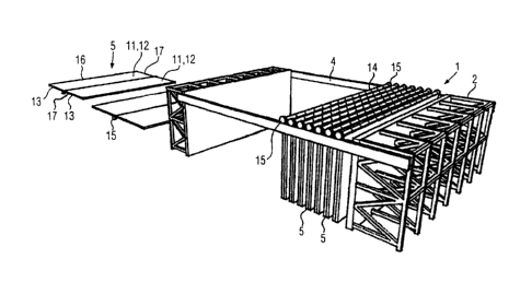
Figure 2 shows a schematic representation of a battery formwork 1 with an
embodiment of a
formwork device 5 according to the invention for the production of structural
elements, not
shown, in particular prefabricated concrete elements. Battery formwork 1 of
Figure 2 is similar to
battery formwork 1 of Figure 1. For reasons of clarity, the attachments such
as stairs, handrail,
etc., and lifting device 7 of Figure 1 have been omitted. Same structural
elements have the
same reference numerals. Battery formwork 1 of Figure 2 differs from battery
formwork 1 of
Figure 1 substantially only by the different configuration of formwork devices
5.
Formwork device 5 according to the invention shown in Figure 2 comprises two
formwork
panels 11 which are connected to each other in an articulated manner in order
to be transferred
from an unfolded state to a folded state. Formwork panels 11 outside battery
formwork 1 show
the unfolded state, and formwork devices 5 disposed within battery formwork 1
show the folded
state. Each formwork panel 11 has a formwork front side 12 for attaching
formwork elements
18, as shown in Figure 3, and a formwork rear side 13. In the folded state,
the formwork rear
sides 13 of the two formwork panels 11 face each other. Formwork panels 11 are
shaped
substantially rectangular, so that also the formwork device is shaped
substantially rectangular.
Such a shape facilitates handling formwork device 5. However, the shape of
formwork device 5
depends on the component to be produced. Therefore, the shape of formwork
device 5 shown
is only by way of example and can be adapted to the circumstances. The
dimension of a
formwork panel 11 preferably corresponds to the dimension of a partition wall
5'.
Formwork panels 11 are connected to one another on one side at the longer
longitudinal side
16. Handling of formwork device 5 can be simplified if formwork panels 11 are
connected to
each other by way of a hinge joint 14. At least formwork front side 12 of
formwork panel 11 can
9
= = CA 02986073 2017-11-15
be magnetic in order to facilitate fitting formwork elements 18, as shown in
the example in
Figure 3.
As already mentioned above, the configuration of formwork device 5 depends on
the component
to be produced. Therefore, formwork panels 11 can also be connected to each
other on one
side other than the longer longitudinal side 16, and can comprise a connection
that is different
from a hinge joint 14. If an attachment e.g. with bolts instead of the
magnetic option is selected
as the attachment of formwork elements 18 to formwork panel 11, then it is not
necessary that
formwork front side 12 of formwork panel 11 be magnetic.
In contrast to formwork device 5 shown in Figure 1, formwork device 5
according to the
invention of Figure 2 comprises two formwork panels 11, which are connected to
one another in
an articulated manner. In addition, formwork device 5 according to the
invention shown in Figure
2 has a roller 15 on each narrow side 17 in the region where the two formwork
panels 11 adjoin
each other. Rollers 15 are arranged at hinge joint 14. The number and
arrangement of rollers 15
can be varied depending on the circumstances.
Formwork devices 5 can be moved easier with rollers 15 in battery formwork 1.
Figure 3 shows a schematic representation of battery formwork 1 and of a
conveyor belt 9 for
conveying formwork device 5 according to the invention.
A soiled formwork device 5 is placed from battery formwork 1 in the unfolded
state and with
formwork front side 12 facing upwardly onto a receiving region 19 of conveyor
belt 9. From
there, formwork device 5 is conveyed in the conveying direction Y to a
cleaning region 20 where
formwork device 5 is cleaned and, in particular, freed from concrete residue.
Formwork
elements 18 that are no longer needed later can also be removed there.
Formwork device 5 is subsequently conveyed to a fitting region 21 where new
formwork
elements 18 can be mounted.
Formwork device 5 is conveyed from fitting region 21 back to battery formwork
1 into which it is
then subsequently suspended. This sequence is to be regarded as being by way
of example
only and can be adapted as needed. In particular, the number, arrangement and
configuration
of regions 19, 20, 21 can be varied according to requirements.
, CA 02986073 2017-11-15
Fastening device 24 is intended to temporarily secure prefabricated concrete
elements 28 when
formwork device 5 is removed. Fastening device 25 is intended to temporarily
secure formwork
device 5 to partition wall 5' on the left-hand side in the illustration, while
prefabricated concrete
element 27 is removed. Fastening devices 24 and 25 are there configured as a
folding brackets
to allow formwork device 5 or prefabricated concrete element 28 to be
temporarily secured. In
the illustration according to Figures 12 to 19, partition walls 5' are mounted
on chassis. As
already explained above, the same sequence of operations can also be performed
with such
partition walls 5' that are suspended.
Figure 20 shows a second embodiment of formwork device 5 in which formwork
elements 18
are arranged on both sides of formwork device 5.
Handling of formwork device 5 is significantly facilitated due to the fact
that formwork device 5
according to the invention comprises two formwork panels 2 which are connected
to each other
in an articulated manner to be transferred from an unfolded state to a folded
state. Formwork
device 5 according to the invention can be used more efficiently than
conventional formwork
devices, whereby the production costs for structural elements can be reduced.
11