Note: Descriptions are shown in the official language in which they were submitted.
CA 02986201 2017-11-16
WO 2016/193941
PCT/1B2016/053270
Testing of a medical fluid treatment
FIELD OF INVENTION
The present invention relates to medical treatment systems for example adapted
for providing a dialysis treatment. More specifically, the present invention
relates
to tests of systems, such as integrity tests or functional tests.
STATE OF THE ART
Dialysis systems are used for treating patients with inadequate kidney
function.
Dialysis systems typically include, among other things, a dialysate circuit
comprising a pump. As described in the European Patent EP 1 648 536 B1 which
is incorporated by reference to the present document, said system may comprise
a disposable cassette in which is arranged a fluid pathway of the dialysate
circuit.
As described in the European Patent EP 1 981 566 B1 and the International
Patent Application W02014/020501 Al which are incorporated by reference to
the present document, said disposable cassette may comprise dedicated area
designed to cooperate (operationally coupled) with a sensor (such as for
example
a pressure sensor), pumping mechanism and/or valve actuator.
Preferentially, the dialysis system comprises a disposable cassette and a
reusable machine. The cassette is used only one time while the machine may be
reused with several cassettes over time. Usually, the machine comprises
expensive elements such as: actuator(s), sensor(s) or pumping mechanism(s).
Said elements are designed in such a way as to cooperate with dedicated areas
of the cassette. A dedicated area may comprise a flexible membrane adapted to
be operationally coupled with a pressure sensor so as to allow a pressure
communication between a fluid which flows through the cassette and the
pressure
sensor.
It is common in dialysis systems to perform some tests that attempt to verify
several features of the system, such as the integrity of the fluid pathway of
the
disposable cassette, the functioning of the valves and/or the pump. These
tests
1
CA 02986201 2017-11-16
WO 2016/193941
PCT/1B2016/053270
are always performed before starting the treatment and the vast majority of
these
tests are performed to check that no leakage (of the fluid which flows into
the fluid
pathway of the cassette) occurs. But other problems may occur and the prior
art
systems are not adapted or designed to find these other failures.
For example, in operating configuration, the cassette is coupled to the
machine
and each element has to be correctly interfaced with its dedicated area. But,
the
coupling between the cassette and the machine may sometimes fail. In this
case,
some elements cannot be fully operated with the risk of, for example,
compromising the efficiency or the safety of the treatment. Thus, said defects
have to be detected so as to ensure the safety of the patient.
Furthermore, some elements may wear over time, for example the sensors. Thus,
it should be noticed that the sensor should also be tested in such a way as to
check the smooth operating of the sensor.
The present invention overcomes the drawbacks of the prior art by performing
other tests so as to increase the patient security and/or to monitor the
operating
elements of the system.
A discussion of the features and advantages of the present invention is
deferred
to the following description, which proceeds with reference to the
accompanying
drawings.
The figures la and lb show a pressure sensor and a part of a disposable
cassette (in particular, an area which is dedicated to the pressure
measurement).
In the figure la, the sensor and the dedicated area are correctly interfaced
while
in the figure lb, the sensor and the dedicated area are not correctly
interfaced.
The gap between both elements is overly emphasized as to better visualize the
difference between the two situations. Nevertheless, when the sensor is
correctly
coupled with the dedicated area, a small volume of a fluid (for example air)
is
potentially trapped between the sensor and the dedicated area of the cassette.
The coupling has to be tight so that the sensor measures pressures.
2
CA 02986201 2017-11-16
WO 2016/193941
PCT/1B2016/053270
The present description makes a distinction between the fluid which flows
through
the fluid pathway of the cassette and the fluid trapped as described above.
The
fluid which flows through the fluid pathway may be blood, water, drug or
dialysate
and the fluid which is trapped between the sensor and the dedicated area of
the
cassette may be a gas or a liquid but, preferentially, it is different from
the fluid
which flows through the fluid pathway of the cassette. Nevertheless, before
the
priming of the fluid pathway (or after the treatment), the fluid which is into
the fluid
pathway (of the cassette) may be air. Thus, if the test is performed before
the
priming or after the treatment, the fluid which flows - during the test -
through the
fluid pathway may be substantially similar for example: air.
When the fluid (which flows into the cassette) is subjected to a greater
pressure
than the atmospheric pressure (in other terms, when the fluid pressure is
positive), the membrane of the dedicated area may come into contact with (or
may move or may be deformed towards) the sensor. Thus, the membrane and/or
the fluid trapped push a surface of the sensor and the sensor measures a
pressure. But, when the fluid (which flows into the cassette) is subjected to
a
lower pressure than the atmospheric pressure (in other terms, when the fluid
pressure is negative), a good or sufficient coupling between the dedicated
area
and the sensor is necessary for measuring such negative pressure. Indeed, the
membrane of the dedicated area may move or may be deformed in a direction
opposite of the sensor and thus the depression of the trapped fluid allows
measuring a negative pressure (in one embodiment, the depression of the fluid
trapped pulls a surface of the sensor so as to measure a negative pressure).
Thus, no leakage shall occur between both elements. In other terms, the fluid
pressure of the fluid (which flows through or in the cassette) is transmitted
to a
surface of the sensor (or to the sensor) via the membrane and/or the fluid
trapped
(between the membrane of the cassette and the surface of the sensor).
In the case where a leakage of the trapped fluid occurs, if the pressure of
the fluid
(which flows through the fluid pathway of the cassette) is positive, the
pressure
sensor may still be able to measure a positive pressure: for example the
3
CA 02986201 2017-11-16
WO 2016/193941
PCT/1B2016/053270
membrane of the cassette will come into contact with the surface of the sensor
and pressure can be measured. But if the pressure of the fluid (which flows
through the fluid pathway of the cassette) is negative, the surface of the
sensor
will not be influenced by the deformation of the membrane of the cassette and
the
pressure sensor may potentially measure the atmospheric pressure. In other
terms, the negative pressure cannot be measured due to the leakage of the
fluid
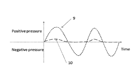
trapped. For example, the curve (9) of the figure 3 represents the real
pressure of
the fluid flowing through the fluid pathway of the cassette but the curve (10)
of the
figure 3 shows data measured by a pressure sensor of the machine when a
leakage of the fluid trapped occurs. Both curves (9, 10) should be the same
but
the curve (10) records a low underestimated positive pressure (caused by the
imperfect contact of the membrane against the sensor) and no negative
pressures
is detected.
When the leakage is limited or if the sensor is not totally defective, the
data
measured may record positive and negative pressures. Nevertheless, the data
measured may be substantially different from the real pressure and it may be
hazardous for the patient or the treatment. Thus, in this case, the system
cannot
detect the failure.
Usually, one solution is to include two redundant sensors in the system so as
to
compare the data of both sensors. Thus the primary sensor is compared to the
second sensor so as to detect a failure of sensor(s). This first solution may
detect
a failure of one sensor, in particular when one of said sensors measures a
pressure which is close to the atmospheric pressure or when one of said
sensors
is totally defective. But when the coupling (for example of both sensors) is
not
perfectly working, both sensors may record the same data and the system cannot
detect any defect.
Furthermore, due to the wear of the system, the coupling or the sensor may be
gradually deteriorated without the system even noticing it. Indeed, even if
the
sensor records negative and positive pressures, the system may get defective.
4
CA 02986201 2017-11-16
WO 2016/193941
PCT/1B2016/053270
Thus, preferably, the machine and/or the cassette should be changed before
this
failure affects patient health.
GENERAL DESCRIPTION OF THE INVENTION
The aim of the invention is to detect an operating failure due to a bad
coupling or
a defective element (such as a sensor) as quickly as possible so as to limit
the
impact to the patient's health. The present document describes distinct
methods
to detect such failure which may be used alone or together:
A test in which a pump generates a pressure;
The monitoring of the pulsation amplitudes which are generated by the
pump during, for example, the treatment;
The drop and/or the increase of the pressure generated by the fluid
which flows through the fluid pathway, for example during the treatment;
A final test in which a pump generates a pressure.
A first aspect of the invention is a method for detecting a failure in a
system
adapted to provide a medical treatment to a patient. This system may comprise
a
fluid pathway (removably and/or fluidically) connected to the patient and be
adapted to infuse or to remove a fluid to or from the patient via the fluid
pathway.
In one embodiment, the method may comprise the following successive steps:
After the medical treatment is completed, blocking the fluidic
communication between the patient and the fluid pathway;
Performing a test so as to detect a failure, wherein the test consists in
checking a feature of the fluid pathway or an element interacting with
the fluid pathway.
As used herein, "blocking" refers to an action which allows preventing or
avoiding
the fluid communication by closing or by cutting or by disconnecting the fluid
pathway to the patient.
5
CA 02986201 2017-11-16
WO 2016/193941
PCT/1B2016/053270
In one embodiment, the system comprise a pump adapted to move the fluid
through the fluid pathway and a sensor adapted to measure a feature associated
to the fluid pumped, the method may comprise the following successive steps:
Actuating the pump;
Monitoring the pressure measured by a first sensor;
Sending at least one measured pressure to the processor;
Determining whether a failure is present by processing the measured
pressure.
In one embodiment, the system comprises at least one occlusion element
adapted to block or close the fluid pathway, the method may comprise the
following successive steps:
Closing the fluid pathway via the occlusion element in such a manner
as to define a closed pathway between the pump and the occlusion
element,
Actuating the pump so as to generated a positive or negative
pressure into the closed pathway;
Monitoring the pressure measured by a first sensor which is in
pressure communication with the fluid being in the closed pathway;
Sending at least one measured pressure to the processor;
Determining whether a failure is present by processing the measured
pressure.
A second aspect of the invention is a method for automatically testing the
coupling
between two distinct elements, said method may be performed by a medical
system which may comprise a pump, a sensor, an electronic processor and a
cassette. The cassette may comprise a dedicated area and a fluid pathway. The
dedicated area may be adapted to be removably coupled to the sensor and to be
in interaction with the sensor in such a manner as to monitor the pressure in
the
fluid pathway. The pump id adapted to convey a fluid through the fluid
pathway.
The method is performed to monitor the coupling between the sensor and the
dedicated area; the method may comprise the steps of:
Actuating the pump
6
CA 02986201 2017-11-16
WO 2016/193941
PCT/1B2016/053270
Monitoring the pressure measured by the sensor
Sending the measured pressure to the processor
Processing the data by the processor so as to check the coupling of
said distinct elements.
The fluid pathway may comprise at least one valve which is controlled by the
processor. The method may comprise the following steps closing at least one
valve so as to define a temporarily closed pathway within the fluid pathway.
A third aspect of the invention is a method for monitoring the smooth
operating of
a medical system which may comprise a pump, a sensor, an electronic processor
and a cassette. The cassette may comprise a dedicated area and a fluid pathway
in which a fluid is conveyed by the pump. The dedicated area is adapted to be
removable coupled to the sensor and in fluid or pressure communication with
the
fluid pathway and the sensor, the method may comprise the steps of:
Actuating the pump
Measuring the pulsation amplitudes of the fluid pressure generated
by the pump
Sending the measured data to the processor
Processing the measured data by the processor
A fourth aspect of the invention is a method for monitoring the smooth
operating
of a medical system adapted to perform a medical treatment to a patient. The
medical system may comprise a pump, a sensor, an electronic processor and a
cassette. The cassette may comprise a dedicated area and a fluid pathway in
which a fluid is conveyed by the pump. The dedicated area is adapted to be
removable coupled to the sensor and in fluid or pressure communication with
the
fluid pathway and the sensor, the test method may comprise the steps of:
Actuating the pump
Measuring fluid pressure by the sensor
Sending to the processor
Processing the data by the processor
7
CA 02986201 2017-11-16
WO 2016/193941
PCT/1B2016/053270
In one embodiment, this method is performed after the medical treatment of the
patient has been completed.
In one embodiment, the method may comprise the following steps:
Actuating the pump until a measured pressure by a first sensor
reaches a threshold
Measuring a fluid pressure by a second sensor
Computing by the processor the difference of measured pressures by
both sensors.
LIST OF FIGURES
The present invention will be better understood at the light of the following
detailed description which contains non-limiting examples illustrated by the
following figures:
Figure la and lb show a pressure sensor and a part of a disposable cassette
Figure 2 shows the data (7) measured by a pressure sensor.
Figure 3 shows the data (7) measured by a pressure sensor.
Figure 4 shows an embodiment.
Figure 5 illustrates a fluid pathway of an embodiment.
Figure 6 illustrates an embodiment with arranged elements of the system.
LIST OF ELEMENTS
1 Cassette
2 Fluid pathway
3 Dedicated area
4 Sensor
5 Machine
6 Gap
7 Data of the measured pressure
8 Average of the measured pressure
9 Real pressure of the fluid flowing through the cassette
8
CA 02986201 2017-11-16
WO 2016/193941
PCT/1B2016/053270
Data record by a defective sensor or when a leakage of the fluid trapped
occurs
101 Patient
102 Machine
5 103 Machine
104 Bag of dialysate
105 Bag of waste fluid
106 Processor
107 Pump actuator
10 108 Sensor
109 Display device
110 Valve actuator
111 Other means
201 pump
202, 203 specific area
204, 205 sensor
206, 207 occlusion element
208 first end
209 second end
300 medical system
301 patient
302 supply bag
303 waste fluid bag
304, 305, 306, 311, 312 occlusion element
307 pump
308, 309, 310 sensor
DETAILED DESCRIPTION OF THE INVENTION
In the following detailed description, reference is made to the accompanying
drawings that form a part hereof, and in which are shown by way of
illustration
9
CA 02986201 2017-11-16
WO 2016/193941
PCT/1B2016/053270
several embodiments of devices, systems and methods. It is to be understood
that other embodiments are contemplated and may be made without departing
from the scope or spirit of the present disclosure. The following detailed
description, therefore, is not to be taken in a limiting sense.
All scientific and technical terms used herein have meanings commonly used in
the art unless otherwise specified. The definitions provided herein are to
facilitate
understanding of certain terms used frequently herein and are not meant to
limit
the scope of the present disclosure.
As used in this specification and the appended claims, the singular forms "a",
"an", and "the" encompass embodiments having plural referents, unless the
content clearly dictates otherwise.
As used in this specification and the appended claims, any direction referred
to
herein, such as "top", "bottom", "left", "right", "upper", "lower", and other
directions
or orientations are described herein for clarity in reference to the figures
and are
not intended to be limiting of an actual device or system. Devices and systems
described herein may be used in a number of directions and orientations.
As used herein, "have", "having", "include", "including", "comprise",
"comprising"
or the like are used in their open ended sense, and generally mean "including,
but
not limited to.
As used in this specification and the appended claims, the term "or" is
generally
employed in its sense including "and/or" unless the content clearly dictates
otherwise.
The figure 4 illustrates a dialysis treatment system which comprises a
dialysate
circuit, a pump and at least one bag for fresh or waste dialysate. The patient
(for
example, in case of peritoneal dialysis, the peritoneal cavity of the
patient), the
dialysate circuit, a part of the pump and/or the bag may be fluidly connected.
The
system may further comprise a pump actuator (107), at least one sensor (108),
a
CA 02986201 2017-11-16
WO 2016/193941
PCT/1B2016/053270
display device (109) (which may be a touch screen) and other means (110, 111),
for example input means (keypad, bouton,...). All of these elements may be
connected to, and/or used with and/or controlled by an electronic processor
(106).
Preferentially, the system comprises a machine (102) (for example a cycler)
which
may comprise expensive and reusable elements and a cassette (103) which may
comprise a part of the fluid pathway and occlusion means adapted to direct a
fluid
(for example dialysate) through the fluid pathway. The cassette may comprise
at
least one tube which extends from the cassette to bag and/or patient in a way
as
to make a fluid pathway in fluid communication with the peritoneal cavity of
the
patient and/or a supply bag (104) and/or a waste bag (105). The fluid may be
directed thanks to the fluid pathway and the opening or the closing of the
occlusion means). The machine (102) is adapted to be operationally coupled
with
the cassette (103) which may be a disposable element as described above.
The machine may comprise at least one sensor (108) (for example a pressure
sensor) and a pump actuator (107) which actuates a pump designed to move a
fluid through the fluid pathway of the cassette. The cassette (103) may
comprise
dedicated area(s) designed to cooperate with the sensor or pump actuator of
the
machine. The dedicated area is adapted to be in fluid or pressure
communication
with the fluid which flows through the fluid pathway. And, the dedicated area
may
be adapted to be in fluid or pressure communication with the sensor. The
sensor
may be adapted to measures a fluid pressure of the fluid which flows through
the
fluid pathway. The dedicated area may be made of a flexible membrane. In
operating configuration, the dedicated area has to be correctly coupled to the
sensor so as to measure correctly the pressure. In one embodiment, the machine
may comprise at least one valve actuator (110) designed to cooperate with
another dedicated area of the cassette (for example occlusion means or valve
which closes the fluid pathway in the cassette) as to close or open a fluid
pathway
of said cassette. The system may comprise other occlusion means (for example
clamp) which may be arranged on and/or adapted to close the fluid pathway of
the
system (for example on the tube which extends from the cassette to the patient
or
bag).
11
CA 02986201 2017-11-16
WO 2016/193941
PCT/1B2016/053270
The pump may be activated in a way as to generate a positive or negative fluid
pressure into the fluid pathway (in particular if a occlusion means closes a
part of
the fluid pathway). The fluid used during the test may be a dialysate solution
or
other (gas (air,...), liquid,...).
The figure la shows a dedicated area (3) of the cassette (1) which is
correctly
coupled to a sensor (4) of the machine (5), some fluid (for example air) may
be
trapped between the dedicated area (which may be a flexible membrane) and a
surface of the sensor, in particular a surface which can measure a pressure.
The
figure lb shows a dedicated area (3) which is not correctly coupled to the
sensor
(4), a gap (6) is between said area (3) and the sensor (4). In this last case,
the
fluid (air) cannot be trapped between the membrane and the sensor. In both
figures, the cassette comprises a fluid pathway (2) which is in fluid and/or
pressure communication with the dedicated area (3). Said dedicated area
transmits the pressure (of the fluid which is into the fluid pathway (2)) to
the
sensor (4). As described above, the negative pressure can be measured by the
sensor only if said elements are correctly coupled.
As described above, the system may comprise an occlusion element (so called
occlusion means) allowing the closing of a part of the fluid pathway. Said
occlusion element may be closed during at least a part of the test. Said
occlusion
element may be a valve of the cassette (as described above), a connector cap,
clamp,... Thanks to this occlusion element, during the test, the system may
determine a part of the fluid pathway in which the test will be performed. For
example, as shown by the figure 5, if the system tests the sensor (204,
respectively 205) which is downstream (respectively upstream) of a pump (201),
the system may close an occlusion element (206, respectively 207) which is
located before (respectively after) the sensor (204, respectively 205). In
other
terms, the system may close the fluid pathway (208, 202, 203, 209) of the
dialysate circuit so as to define a temporarily closed pathway (202, 203)
within the
fluid pathway, which extends from a valve (206) to a pump (201) (or from a
pump
(201) to a valve (207)). Preferentially, said temporarily closed pathway
comprises
12
CA 02986201 2017-11-16
WO 2016/193941
PCT/1B2016/053270
at least one dedicated area (as described above) adapted to cooperate with a
sensor (204, 205) which is used for the test.
Failure detected by a test generating a pressure by a pump
In this test, the pump generates a pressure preferentially in a temporarily
closed
pathway (as described above). The system controls the pump and monitors the
sensor during the test. The objective of such test is to detect that the
pressure
data reaches a pre-determined threshold. Thus, the pump is actuated by the
system so as to generate a negative or positive pressure in the temporarily
closed
pathway which cooperates with the tested element (as the pressure sensor or
the
coupling). Said test may comprise other condition(s), for example, the
threshold
has to be reached before a predetermined time interval or a predetermined
number of pump strokes or a predetermined volume of fluid pumped... After the
test, the system may stop the pump and may pass to another test or to the
treatment. For example, if the system concludes to a failure or a success, the
system passes to another test (for example so as to confirm the result or to
check
others elements) and/or records the data in a memory of the system and/or
performs the treatment.
These other conditions of the test may be also used to limit the test duration
or the
fluid volume which is pumped during the test. Thus, the system may stop the
test
after a predetermined time or after a predetermined number of strokes or when
a
predetermined volume of fluid has been pumped.
Preferentially, if condition is not met (for example: the data of the measured
pressure does not reach the predetermined threshold during a predetermined
number of pump strokes), then the system may conclude to a failure.
During this test, the system may maintain a pressure into the temporarily
closed
pathway and monitor, over a certain time, the pressure measured by the tested
13
CA 02986201 2017-11-16
WO 2016/193941
PCT/1B2016/053270
sensor. If the data of the measured pressure goes beyond a predetermined range
(e.g. decays faster than a given rate), the system may conclude to a failure.
The test may comprise the following step:
= Closing the fluid pathway with an occlusion element to define a
temporarily and determined closed pathway (202, 203) within the fluid
pathway;
= Actuating the pump (201) to generate (successively) a predetermined
positive and/or a negative pressures in said temporarily and
determined closed pathway (202, 203);
= Sending, to the processor, data of the pressure sensor (204, 205)
which is in pressure communication with said temporarily and
determined closed pathway (202, 203);
= Analyzing by the processor the received pressure data from the
pressure sensor.
Optionally, the system maintains the positive and/or the negative pressures
during
a predetermined duration and the system monitors the profile of the pressure
data
during said predetermined duration. To maintain the pressure, the system may
stop the pump or actuate slowly the pump.
The pump may generate a positive pressure so as to detect a leakage of the
fluid
which flows into the fluid pathway. And the pump may generate a negative
pressure so as to detect a leakage of the fluid trapped between the sensor and
the membrane (the dedicated area which is adapted to cooperate with the
sensor). Thus, a failure of coupling may be preferentially detected thanks to
the
negative pressure generated by the pump.
The pump (201) may be a peristaltic pump or a diaphragm pump. In this last
case,
the element (201) may comprise additional valves dedicated to the pump
mechanism. As shown in the figure 5, in a normal actuation mode, the pump
(201)
moves the fluid from a first end (208) of the fluid pathway to a second end
(209) of
the fluid pathway and, in a reverse actuation mode, the pump (201) moves the
14
CA 02986201 2017-11-16
WO 2016/193941
PCT/1B2016/053270
fluid from the second end (209) of the fluid pathway to the first end (208) of
the
fluid pathway.
The test may check two distinct sensors (204, 205), a first sensor (204) which
is
located downstream of a pump (201) and a second sensor (205) which is located
upstream of a pump (201). Four distinct tests may be successively performed
(the
order of the following step can be changed):
= Generating a positive pressure in the temporarily closed pathway
(203) which is in pressure communication with the second sensor
(205);
= Generating a positive pressure in the temporarily closed pathway
(202) which is in pressure communication with the first sensor (204);
= Generating a negative pressure in the temporarily closed pathway
(202) which is in pressure communication with the first sensor (204);
= Generating a
negative pressure in the temporarily closed pathway
(203) which is in pressure communication with the second sensor
(205).
To generate a positive pressure in the first temporarily closed pathway (202),
the
pump may be actuated in the reverse actuating mode, the first valve (206) is
closed and the second valve (207) is open. To generate a negative pressure in
the first temporarily closed pathway (202), the pump may be actuated in the
normal actuating mode, the first valve (206) is closed and the second valve
(207)
may be open. To generate a positive pressure in the second temporarily closed
pathway (202), the pump may be actuated in the normal actuating mode, the
first
valve (206) is open and the second valve (207) is closed. To generate a
negative
pressure in the second temporarily closed pathway (202), the pump may be
actuated in the reverse actuating mode, the first valve (206) may be open and
the
second valve (207) is closed.
The processor analyzes the received pressure data from the first and second
sensors. If during the first test, the received pressure data from the first
sensor
reaches a predetermined threshold (for example during a predetermined number
CA 02986201 2017-11-16
WO 2016/193941
PCT/1B2016/053270
of pump strokes), then the process may conclude that no leakage of the fluid
occurred in a part of fluid pathway downstream of the pump (201). If during
the
second test, the received pressure data from the first sensor reaches a
predetermined threshold (for example during a predetermined number of pump
strokes), then the process may conclude that the first sensor is correctly
coupled
to the cassette. If during the third test, the received pressure data datafrom
the
second sensor reaches a predetermined threshold (for example during a
predetermined number of pump strokes), then the process may conclude that no
leakage of the fluid occurred in a part of fluid pathway upstream of the pump
(201). If during the fourth test, the received pressure data datafrom the
second
sensor reaches a predetermined threshold (for example during a predetermined
number of pump strokes), then the process may conclude that the second sensor
is correctly coupled to the cassette.
If any of those received pressure data cannot reach the predetermined
threshold
or maintain a value above such threshold over a certain time, then the system
may indicate to the patient or caregiver (which may be located on other area)
via
a screen, e-mail or audio indication that the system cannot perform the
treatment.
If only few received pressure data cannot reach the predetermined threshold or
maintain a value above such threshold over a certain time, then the system may
indicate this information only to the caregiver and it may perform the
treatment in
a safety operating mode (as described in the European patent application
number
EP 14189455.0 which is incorporated by reference to the present document) in
which the result of treatment is not optimal but better than no treatment,
while the
security for the patient is ensured via a modified treatment cycle.
This test or a similar test may be performed when the patient is no longer
fluidly
connected to the system (for example to the dialysate circuit of the system).
Thus,
the fluid pathway may comprise an element adapted to prevent the fluidic
communication between the fluid pathway of the system (for example the
cassette) and the patient (for example to the peritoneal cavity of the
patient). For
example, the system may comprise an occlusion element which closes the fluid
pathway between the cassette and the patient (such as for example a valve, a
16
CA 02986201 2017-11-16
WO 2016/193941
PCT/1B2016/053270
clamp,...). The system may also comprise a connector which allows the fluid
communication between the system and the patient during the treatment. In this
case, the patient can disconnect from the system before the test procedure.
This
connector may further comprise a cap which may be used to close this end of
the
fluid pathway during the test procedure. Before to start the test procedure,
the
system may check that the patient is no longer in fluid communication with the
system. For example, the system may actuate the pump and monitor the pressure
data.
The fluid circuit may comprise a flexible area (for example a tube, a
membrane, a
connector, a wall of the cassette,...). Said flexible area may be deformed
over
time by the pressure generated by the pump. Thus, the system has to use a
mathematical model which takes into account this deformation over time.
Because, the fluid pressure may change over time due to the deformation of the
flexible area. Thus, the system has to determine if the evolution of the
pressure
data is due to a leakage or the deformation of the flexible area (for example
the
flexible tube of the system).
The system may perform these tests over a short period of time and therefore
the
system doesn't have to take into account the thermal evolution which may cause
over time a drift of the pressure.
Failure detected by the pulsation amplitude
If the pump is a diaphragm pump or a peristaltic pump, both may generate
pulsations (peaks of pressure) which shall be detected by a pressure sensor.
The
figure 2 shows the data (7) measured by a pressure sensor. Said data (7) draws
a
curve of the pulsations generated by a peristaltic pump. Said curve (7)
comprises
maximum pressure peak and minimum pressure peak. The curve (8) is the
average of the data (7).
This test may be performed after a previous test, for example if the system
does
not detect any defect. It may be performed when the patient is fluidly
connected to
17
CA 02986201 2017-11-16
WO 2016/193941
PCT/1B2016/053270
the fluid pathway (for example the dialysate circuit) before the treatment
and/or
during the treatment and/or after the treatment. During the test, unlike the
test
previously described, the system may not define a temporarily closed pathway
within the fluid pathway.
When the sensor and the dedicated area are not correctly coupled (or if a
sensor
has a defect), the pressure data sent by the pressure sensor is not
substantially
equal to the "normal" profile of predetermined data. The "normal" profile of
predetermined data is the profile of data which corresponds to the measured
pressure pulsations when the system operates correctly. The processor may
compare the received pressure data from the pressure sensor to predetermined
data so as to detect a defect.
Preferentially, the test comprises the following steps:
= Optionally,
opening valves of a fluid pathway which extends from a
supply of fluid to a receiver of fluid,
= Actuating a pump,
= Sending to the processor the pressure data measured by a pressure
sensor which is in pressure communication with the fluid moved by
the pump,
= Analysing by a processor the received pressure data from the sensor.
The supply of fluid and the receiver of fluid may be a cavity of the patient
(for
example the peritoneal cavity) or a bag.
The processor may use a mathematical model to analyse the data, for example to
compare the pressure data measure to a reference (range, threshold, computed
data,...).
During this test, the processor may monitor, for example, the minimum, maximum
of a peak of pressure data and/or average values (8) of the pressure data.
Thus,
the processor may compare:
18
CA 02986201 2017-11-16
WO 2016/193941
PCT/1B2016/053270
= A minimum of the pressure data to a predetermined threshold or to a
predetermined range, and/or
= A maximum of the pressure data to a predetermined threshold or to a
predetermined range, and/or
= The average of
the minimum of the pressure data to a predetermined
threshold or to a predetermined range, and/or
= The average of the maximum of the pressure data to a predetermined
threshold or to a predetermined range, and/or
= The difference between a minimum and a maximum of the pressure
data to a predetermined threshold or to a predetermined range,
and/or
= The difference between the average of the minimum and the average
of the maximum of the pressure data to a predetermined threshold or
to a predetermined range.
For example, in case where the processor computes the difference between a top
pressure data (a maximum of the pressure data) and the bottom pressure data (a
minimum of the pressure data) during a predetermined duration, (in other terms
the difference between the maximum and the minimum measured data) the
difference has to be higher than 10 mbar, 20 mbar or 50 mbar so as to conclude
to a smooth operating of the system.
If data monitored by the processor is not correct, the system may conclude to
a
defect. This defect may trigger an alarm to inform the patient or a caregiver
or
may be recorded to a memory of the system to be used after.
Said test may be performed at a specific time (before or during the treatment)
or
over time of the treatment.
Failure detected by the drop and/or the increase of the pressure
generated by the fluid into the fluid pathway
The pumping of the fluid generates some fluid frictions against the walls of
the
cassette. Said pressure caused by the friction depends on the flowrate of the
fluid,
19
CA 02986201 2017-11-16
WO 2016/193941
PCT/1B2016/053270
the shape of the fluid pathway, and the features of the fluid and of the fluid
pathway. This pressure may be computed for example using the formula
Poiseuille-Hagen. This formula is valid in the case of a pressure generated by
a
laminar flow in a tube.
When a peristaltic pump is actuated in a normal actuating mode, a negative
pressure is generated upstream the pump (201) and a positive pressure is
generated downstream the pump (201). As described above, when the coupling is
not correct, the system cannot measure the negative pressures while the
positive
pressure may be more easily measured. Thus, it would be better to monitor the
pressure in the fluid pathway located before the pump.
If a small leakage occurs between the sensor and the dedicated area, the
measured pressure slowly derives. A threshold or a range may be determined and
if the measured pressure reaches said parameters, during the treatment, the
system has to act so as to ensure patient safety.
In the case of the peritoneal dialysis treatment, the system performs several
cycles of fill, dwell and drain phases. During the fill and the drain phases,
the
pump is actuated so as to move the dialysate from the supply by to the
peritoneal
cavity of the patient and from the peritoneal cavity of the patient to a waste
fluid
bag.
During the test, the system receives the pressure data from the pressure
sensor
before starting the actuating of the pump. Said pressure data is recorded in a
memory of the system and is compared to the pressure data when the pump is
actuated. The description of this test is fully described into the European
patent
application EP 14189455.0 which is integrally integrated into the present
document.
The test comprises the following steps:
= Receiving a pressure data from a pressure sensor when the pump is
not actuated
CA 02986201 2017-11-16
WO 2016/193941
PCT/1B2016/053270
= Actuating the pump so as to move a fluid through a fluid pathway at a
specific flow rate
= Receiving the pressure data from the pressure sensor when the
pump is actuated
= Computing an average of the pressure data when the pump is
actuated
= Computing the difference between the pressure data when the pump
is not actuated and the average of the pressure data when the pump
is actuated
Preferentially, if the value computed during the last step does not reach a
predetermined value, the system performs the following steps:
= Stop the pump,
= Receive a pressure data from a pressure sensor when the pump is
not actuated (optionally)
= Actuate the pump so as to moves the fluid at a flow rate lower than
the previous flow rate
= Receive the pressure data from the pressure sensor when the pump
is actuated
= Compute an average of the new pressure data when the pump is
actuated
= Compute the difference between the pressure data when the pump is
not actuated and the new average of the pressure data when the
pump is actuated
Failure detected by a final test in which a pump generates a
greater pressure
Some tests cannot detect the failures which could have long-term impacts for
the
patient health. In other case, some tests minimizes the failure (in other
terms, the
failure seem be less important). For example, the wear of the system gradually
21
CA 02986201 2017-11-16
WO 2016/193941
PCT/1B2016/053270
causes a deterioration of the treatment effectiveness, and the accumulation of
these less effective treatments can be hazardous for the patient. Thus, these
failures have to be also detected and thus, other tests should be performed.
The detection of these failures is more complex and may be dangerous for the
patient, in particular if the patient is in fluid communication with the
fluidic circuit
(which is tested) and/or if the test is performed before or during the
treatment.
Indeed, to detect these failures, the system may perform extreme tests during
a
longer period of time or until a partial or complete destruction of the
disposable
elements (tube, connector, membrane of the cassette, cassette,...). For
example,
the aim of the new tests may be to generate a greater pressure in the
dialysate
circuit which can deform some element of the cassette (membrane, tube,...).
Thus, such test cannot be performed before or during the treatment. In other
terms, these other tests may damage the cassette. Thus, these tests should be
performed after the treatment, preferentially when the patient is fluidly
disconnected from the system. For example if the medical treatment is a
peritoneal treatment, the peritoneal cavity of the patient does not have to be
in
fluid communication with the dialysate circuit during these tests, thus the
patient
can disconnect the patient line and/or close a clamp on the patient line.
During this test, the processor may use a mathematical model so as to detect a
failure, for example a mathematical model as described above.
For example, if this test is performed on the embodiment shown in the figure
6,
the system (300) comprises dialysate circuit which extends between the patient
(301) or the supply bag (302) and the waste fluid bag (303), a pump (307) and
at
least two pressure sensors (308, 309, 310). The dialysate circuit comprises a
supply line, a patient line and a waste line which are respectively fluidly
connected
to the supply bag, the patient and the waste fluid bag. The system may
comprise
an occlusion element (clamp, valve, cap of connector,...), said occlusion
element
(304, 306, 311, 305, 312) may close the supply line, the patient line and/or
the
waste line. Between the patient and the occlusion element (311) of the patient
line, a connector (not shown) may be adapted so as to disconnect the patient
form
the patient line. The at least two pressure sensors may be a patient pressure
22
CA 02986201 2017-11-16
WO 2016/193941
PCT/1B2016/053270
sensor (309) which is in pressure communication with the patient line, a
supply
pressure sensor (308) which is in pressure communication with the supply line
and/or a waste pressure sensor (310) which is in pressure communication with
the waste line.
The sensors, the occlusion element and the pump may be electronically
connected to the processor (not shown in the figure 6).
At the end of the treatment (for example after the medical treatment has been
performed), the patient has to be disconnected from the dialysate circuit of
the
system (or at least no longer in fluid communication). According to the figure
6, if
the system has two occlusion elements (306, 311), the occlusion element which
is
located between the pump and the patient pressure sensor has to be open while
the occlusion element between the patient pressure sensor and the end of the
patient line (which is adapted to be connected to the patient) has to be
closed.
The occlusion element (312) may be also closed.
Optionally, the system may actuate the pump so as to check that the patient is
correctly disconnected from the dialysate circuit. If the pressure sensor
(309)
records a drop of the pressure (for example until -80 mbar +/-80 mbar
preferentially +/- 40 mbar or +/- 10 mbar) then the patient is correctly
disconnected and/or the occlusion element (311) operates on the patient line.
If
the pump moves for example between 1 and 10 mL (preferentially 5 or 4 or 2 mL)
without reaching -80 mbar then the patient is in fluid communication with the
system.
During the test, the valves (305 and 306) are preferentially open.
During the test, the system may actuate the pump (307) so as to move the fluid
from the patient line or supply line to the waste line and/or vice versa.
The test comprises the following steps:
= Disconnecting the patient from the dialysate circuit,
23
CA 02986201 2017-11-16
WO 2016/193941
PCT/1B2016/053270
= Actuating the pump so as to generate a pressure measured by the
supply pressure sensor and/or the patient pressure sensor,
= Analysing by the processor the received pressure data from the
supply pressure sensor and/or the patient pressure sensor.
Preferentially, the pump moves the fluid at a flowrate of 50 mL/min or 20
mL/min
+/-20 mL /min preferentially +/- 5 mL /min or +/- 2 mL /min. To test the
disconnection of the patient line, the pump may pump at 20mL/min and to
perform
the final test, the pump may pump at 50 mL/min.
The pump may be adapted to generate a pressure higher than +/-200 mbar +/-
10%. In this case, the pump is actuated until one sensor measures a pressure
substantially equal to a predetermined threshold, for example +/-200 mbar +/-
10%. Thus during the final test, the pump may be actuated until to reach -200
mbar (measured by the pressure sensors (308 and or 309). If the pump moves for
example between 1 and 20 mL of fluid during the test (preferentially 15 or 10
or 5
mL) without reaching -200 mbar then the processor stops the test.
For example, the pump is actuated so as to generate a negative pressure
(respectively a positive pressure) in the fluid pathway of the patient line
and the
supply line. The occlusion elements (304, 311 and/or 312) may be closed while
the occlusion element (306) may be open. Both sensors monitor the pressure in
its respective line. When one of both sensors measures a pressure which has
reached a predetermine threshold (for example -250 mbar, -220 mbar, -200 mbar,
-180 mbar or -150 mbar (or respectively +250 mbar, +220 mbar, +200 mbar, +180
mbar or +150 mbar)) the processor compares the measured pressure of both
sensors. If the difference of measured pressure is equal to or lower than a
predetermined threshold (for example +/-50 mbar or +/-40 mbar or +/-30mbar)
then the processor may conclude to a smooth operation of the system. If the
difference is higher than the predetermined threshold, the system may store
the
data in a memory or send this data to a remote server via internet and
determine
that the device has potentially a problem.
24
CA 02986201 2017-11-16
WO 2016/193941
PCT/1B2016/053270
The system may store several data of this difference and it may use this data
to
monitor a trend, for example the number of times that the threshold is reached
or
the proportion of the threshold reached. If one or all conditions is reached,
then
the system may indicate to the patient (via a screen of the system or other
indication device) that the system requires maintenance (now or in few days or
before a number of treatments) and/or may send this information to a remote
service center via e.g. internet.
Preferentially, the pump is actuated during a predetermined time or until
reaching
a predetermined number of pump strokes or a predetermined pressure or when a
predetermined volume has been moves by the pump (for example 10 ml, 5 ml or 4
ml preferentially +/- 2 ml or +/- 1 ml).
For all tests, the device may record the data of the test and/or a report of
the test
and/or alerts the patient. Said data or report may be monitored by the
processor in
such a manner as to predict a potential future failure of an element or to
predict
the overhaul date of the device (as the expected date of revision). All or
part of
these data may be sent to a remote server.
Such final test (done after completion of the treatment and while the patient
is
disconnected from the device) can be extremely useful to confirm the normal
operation of the device and/or detection of specific malfunctions, without
requiring
a specific servicing nor extra cost or time (the set used for such test is the
same
as the one used for the treatment which is, at such time, to be discarded).