Note: Descriptions are shown in the official language in which they were submitted.
CA 02986323 2017-11-17
WO 2017/009002
PCT/EP2016/064079
- 1 -
PRODUCING AN AEROSOL-FORMING COMPOSITION
The present invention relates to a machine and method for producing an aerosol-
forming
composition for use in an aerosol-generating system, for example an
electrically operated
aerosol-generating system. In particular, aspects of the present invention
relate to a machine
and method for producing an aerosol-forming composition for use in an
electrically operated
aerosol-generating system.
One type of aerosol-generating system is an electrically operated smoking
system. A
number of prior art documents, for example US-A-5060 671, US-A-5 388 594, US-A-
5 505 214,
US-A-5 591 368, WO-A-2004/043175, EP-A-0 358 002, EP-A-0 295 122, EP-A-1 618
803, EP¨
A-1 736 065 and WO-A-2007/131449, disclose electrically operated smoking
systems, having a
number of advantages. One advantage of some examples described is that they
can reduce
sidestream smoke, while permitting the smoker to selectively suspend and
reinitiate smoking.
Handheld electrically operated smoking systems consisting of a device portion
comprising
a battery and control electronics, and a cartridge portion comprising a supply
of aerosol-forming
substrate, and an electrically operated vapouriser, are known. A cartridge
comprising both a
supply of aerosol-forming substrate and a vapouriser is sometimes referred to
as a "cartomiser".
The cartridge portion typically comprises not only the supply of aerosol-
forming substrate and an
electrically operated heater assembly, but also a mouthpiece, which the user
sucks on in use to
draw aerosol into their mouth. The vapouriser is typically a heater assembly
for example
comprising a coil of heater wire wound around an elongate wick soaked in
liquid aerosol-forming
substrate. The aerosol-forming substrate may be a solid aerosol-forming
substrate, such as a
granules or shreds of tobacco-containing material. In some known examples, the
aerosol-forming
substrate is an aerosol-forming liquid, sometimes referred to as an "e-
liquid".
The cartridge may be refillable when the aerosol-forming liquid, or "e-
liquid", is consumed.
Typically, the e-liquid is formulated prior to purchase by the consumer, with
the concentrations of
the e-liquid components being determined by the e-liquid manufacturer. It is
possible for
consumers to buy the components individually and mix the e-liquids themselves.
However,
although such manual preparation of e-liquids allows a user to customise the e-
liquid formulation
as desired, it can be difficult and may require specialist equipment due to
the nature of the e-
liquid components.
It would be desirable to provide a machine for producing an aerosol-forming
composition
for use in an aerosol-generating system, for example a smoking system, for
example an
electrically operated aerosol-generating system, such as a handheld
electrically operated
smoking system.
CA 02986323 2017-11-17
WO 2017/009002
PCT/EP2016/064079
- 2 -
According to a first aspect of the present invention, there is provided a
machine for
producing an aerosol-forming composition for use in an aerosol-generating
system, the machine
comprising: a plurality of reservoirs for containing components of an aerosol-
forming
composition; a mixing mechanism in communication with the plurality of
reservoirs; a controller
connected to the mixing mechanism for control thereof; and a user interface
connected to the
controller for a user to operate the machine, wherein the mixing mechanism is
configured to mix
selective quantities of components from the plurality of reservoirs according
to specified ratios to
create an aerosol-forming composition , and wherein the machine further
comprises a testing
mechanism comprising: a heater assembly for vaporising a test sample of the
composition to
form an aerosol, and at least one outlet for delivering the aerosol to the
user; and a transfer
mechanism for delivering the test sample of the aerosol forming composition to
the testing
mechanism.
Preferably the ratios are specified by the user.
In some examples, the test sample will comprise all or substantially all of
the created
aerosol-forming composition. In other examples, the test sample will be less
than all of the
created composition. For example, less than 50%, less than 20%, less than 10%
or less than 5%
by volume of the created composition may be delivered to the testing
mechanism. For example,
the created composition may have a volume of about 0.5 ml or more, for example
about 2 ml or
more. The created composition may have a volume for example less than about
5m1, for example
less than about 3m1. The test sample may for example be less than about lml,
for example less
than about 0.5 ml, for example less than about 0.2 ml, for example about 0.1m1
or less, for
example about 0.05 ml or less. In some cases, the test sample may include one
or more droplets
of the composition.
The testing mechanism may vaporise substantially all or less than all of the
test sample,
in one or more vaporising operations. In some cases, a second or more test
samples from the
created composition may be delivered to the testing mechanism in two or more
delivery
operations.
In some examples the composition will comprise a liquid composition. Some or
all of the
components comprise liquids. In some examples, one or more components may be
non-liquid,
for example gel. The composition may for example include one or more solid
components for
example particles or other objects. One or more of the reservoirs may deliver
for example a
powder component. In an example, the reservoirs dispense a liquid component
and a non-liquid
component. The non-liquid component may for example dissolve in the liquid
component or may
be present as a non-liquid in the aerosol-forming composition.
Advantageously, the testing mechanism allows the user to test a sample of the
selected
composition directly at the machine. The user can then determine if the
selected composition
CA 02986323 2017-11-17
WO 2017/009002
PCT/EP2016/064079
- 3 -
produces a desirable aerosol before a larger quantity of the formulation is
dispensed. The
machine may mix the components automatically to produce the aerosol-forming
composition, thus
avoiding the need for manual mixing. This may result in a more accurate and
repeatable mix.
In certain examples, the testing mechanism may comprise a fixed, reusable
heater
assembly. Such a heater assembly is intended to be reused by the machine for
multiple testing
procedures. In such examples, the testing mechanism preferably further
comprises a cleaning
device, such as a nozzle for spraying fluid under pressure, with which the
fixed heater assembly
may be cleaned following a testing procedure. This can reduce the possibility
of cross-
contamination between subsequent testing procedures using the machine by
removing portions
of test sample which remain on the heater assembly following aerosolisation.
This may improve
the accuracy of the aerosol produced from the test sample. In other
embodiments, the testing
mechanism comprises a removable heater assembly.
In example embodiments, the machine comprises a heater supply containing a
plurality of
heater assemblies for use with the testing mechanism. The heater assemblies
may be single use
or disposable heater assemblies. The heater supply may comprise one or more
cartridges or
hoppers containing one or more stacks of heater assemblies. After use, a
heater assembly can
be removed from the testing mechanism, disposed of, and replaced with a new
heater assembly
for one or more subsequent testing procedures. With this arrangement, cross-
contamination
between test samples can be reduced. This may improve the accuracy of the
aerosol produced
from the test sample. It also allows a heater assembly to be more easily
replaced if necessary.
Where the machine further comprises a heater supply containing a plurality of
heater
assemblies for use with the testing mechanism, the transfer mechanism may be
arranged to
select a heater assembly from the heater supply for use with the testing
mechanism and deliver
it to a user, for example for placement in the testing mechanism. The
delivered test sample and
heater may then be used in an aerosol generating device. In some examples,
some or all of the
test sample may be transferred to the testing mechanism within the machine.
For example, test
sample material could be delivered onto a heater, for example a resistive
wire, within the machine
to produce an aerosol which is then delivered to the user. In examples of the
invention, test
sample composition may be delivered to a container. Material may be delivered
from the
container to a heater for production of an aerosol. A heater may be selected
for the test process
depending on the container used for the test sample composition.
In an example, test
composition material is applied directly to the heater. For example, the
heater may be dipped in
the test composition material.
In examples, the transfer mechanism is configured to select a heater assembly
from the
heater supply, to apply the test sample on one or more surfaces of the heater
assembly and to
CA 02986323 2017-11-17
WO 2017/009002
PCT/EP2016/064079
- 4 -
deliver the heater assembly to the testing mechanism. The test sample may be
inserted into the
testing mechanism by the machine.
The testing mechanism may be arranged to receive a single type of heater
assembly.
Alternatively, the testing mechanism may be arranged to receive heater
assemblies of different
types. In such embodiments, the machine may comprise a heater supply
containing a plurality of
heater assemblies of different types for use with different types of
electrically operated aerosol-
generating systems. The testing mechanism may be configured to select a heater
assembly from
the heater supply based on a desired type of aerosol-generating system, for
example, the user's
own aerosol-generating system. As different types of aerosol-generating system
may produce
aerosols with different characteristics from the same aerosol-generating
composition in some
cases, by selecting a heater assembly from the heater supply based on a
desired type of aerosol-
generating system, the test sample may be vapourised using a heater assembly
suitable for the
system. For example the heater assembly may be of the same type as that of the
user's aerosol-
generating system or one which gives similar results. Consequently, the
aerosol produced by the
testing mechanism may be closer to the aerosol which would be produced by the
user's aerosol-
generating system from the same formulation, which may give more accurate
testing results. The
desired type of aerosol-generating system may be determined from a user input
via the user
interface. Alternatively, or in addition, the machine may include a sensor for
determining the
desired type of aerosol-generating system automatically, for example via an
RFID connection
between the machine and the user's aerosol-generating system, or via machine-
readable
information on the user's aerosol-generating system, or in another way.
The transfer mechanism may be arranged to apply the test sample on one or more
surfaces of the heater assembly by any suitable method. For example, the
transfer mechanism
comprises a transfer head for applying the test sample to the heater assembly
by spraying the
heater assembly with the test sample, or by dipping the heater assembly into
the test sample, or
by both spraying and dipping.
The testing mechanism may comprise an aerosol-forming chamber in which the
aerosol
forms from a super saturated vapour, which aerosol is then carried into the
mouth of a user.
An air inlet, air outlet and the chamber are preferably arranged so as to
define an airflow route
from the air inlet to the air outlet via the aerosol-forming chamber, so as to
convey the aerosol
to the air outlet and into the mouth of a user.
The machine may comprise a plurality of separate units, for example positioned
adjacent
to each other, each housing one or more components of the machine. In certain
embodiments,
the machine may comprise a single unit in which all of the components of the
machine are housed.
CA 02986323 2017-11-17
WO 2017/009002
PCT/EP2016/064079
- 5 -
In certain preferred embodiments, the machine comprises a main unit in which
the plurality
of reservoirs is housed and the testing mechanism comprises a handheld aerosol-
generating
device that is external to and coupled with the main unit. The aerosol-
generating device is
preferably electrically operated and includes the heater assembly and the at
least one outlet by
which aerosol is delivered to the user.
Having a handheld aerosol-generating device that is external to a main unit
may improve
the ease of use of the testing mechanism by a user.
As used herein, the term "aerosol-generating device" relates to a device that
interacts with
an aerosol-forming substrate to generate an aerosol. An aerosol-generating
device may be a
smoking device that interacts with an aerosol-forming substrate to generate an
aerosol that is
directly inhalable into a user's lungs thorough the user's mouth.
As used herein, the term "aerosol generating system" refers to a combination
of an
aerosol-generating device and one or more aerosol-generating articles, such as
a cartridge or
cartomiser comprising a supply of aerosol-forming substrate, for use with the
device. An aerosol-
generating system may include additional components, such as for example a
charging unit for
recharging an on-board electric power supply in an electrically operated or
electric aerosol-
generating device.
The aerosol-generating device may be coupled to the main unit by a flexible
cable. With
this arrangement, the aerosol-generating device is portable, in that it may be
moved
independently from the main unit, while still remaining tethered. Preferably,
the aerosol-
generating device is coupled to the main unit by a flexible electrical wire.
In such embodiments,
the main unit preferably comprises a power supply for the aerosol-generating
device. This allows
the aerosol-generating device to operate without an integral power supply,
reducing the weight of
the device.
The aerosol generating device may be a smoking device and may have a size
comparable
to a conventional cigar or cigarette. The device may have a total length
between approximately
mm and approximately 150 mm. The device may have an external diameter between
approximately 5 mm and approximately 30 mm, preferably between 10 mm and 20
mm.
The aerosol generating device may comprise a plurality of air inlets. The
number and
30 size of the air flow inlets may be chosen to provide a desired
resistance to draw through the
device. In a smoking device it may be desirable for the resistance to draw
(RTD) through the
device to be close to the resistance to draw of a conventional cigarette.
Resistance to draw is also known as draft resistance, draw resistance, puff
resistance or
puffability, and is the pressure required to force air through the full length
of the object under test
at the rate of 17.5 ml/sec at 22 C and 760 Torr (101 kPa). It is typically
expressed in units of
mmH20 and is measured in accordance with ISO 6565:201 1. The aerosol
generating device may
CA 02986323 2017-11-17
WO 2017/009002
PCT/EP2016/064079
- 6 -
provide an RTD of between 80 and 120 mmH20. This approximates the RTD of a
conventional
cigarette.
The aerosol-generating device may comprise one or more adjustable airflow
modifiers,
such as vanes, inlets or airflow channels, for varying the resistance to draw
through the device.
The adjustable airflow modifiers may be adjusted manually by a user, for
example using an
adjustable dial. Alternatively, or in addition, the adjustable airflow
modifiers may be adjusted by
a controller in the main unit, or by a controller in the aerosol-generating
device. In such
embodiments, the controller may adjust the airflow modifiers based on an input
from the user via
the user interface or via a portable device connected to the machine. In some
embodiments, the
controller adjusts the airflow modifiers automatically to simulate the
resistance to draw of a
desired type of device.
In certain embodiments, the main unit comprises a docking station for the
aerosol-
generating device. The docking station may comprise a sensor for detecting if
the aerosol-
generating device is correctly positioned at the docking station. The sensor
is connected to the
controller. The controller may be configured to display an error message on a
display portion of
the user interface, or to prevent operation of the machine, or both, if the
sensor detects that the
aerosol-generating device is not correctly positioned. The docking station
preferably comprises
a docking port for receiving the aerosol-generating device. The docking port
may comprise a
holding means for holding the aerosol-generating device in the correct
position in the docking
port. For example, the holding means may comprise a complementary shaped
recess, or a clip,
or other suitable known holding means.
In certain embodiments, the machine further comprises a mouthpiece supply
containing a
plurality of disposable mouthpieces for removable coupling with the at least
one outlet of the
testing mechanism. A mouthpiece delivery mechanism may be configured to
deliver a disposable
mouthpiece from the mouthpiece supply for subsequent coupling to the at least
one output of the
testing mechanism. The mouthpiece delivery mechanism may be arranged to
deliver the
mouthpiece to a mouthpiece supply port based on an instruction from the
controller. The
mouthpiece can then be removed from the mouthpiece port by a user and coupled
to the outlet
of the testing mechanism. The machine may also include a mouthpiece disposal
port into which
used mouthpieces can be placed by a user for disposal after use.
As used herein, the term "mouthpiece" refers to a component that is arranged
for
placing on or into a user's mouth in order for the user to directly inhale an
aerosol generated
by the testing mechanism.
The disposable mouthpieces contained in the mouthpiece supply may have an
outer
diameter which substantially corresponds to the inner diameter of the outlet
of the testing
CA 02986323 2017-11-17
WO 2017/009002
PCT/EP2016/064079
- 7 -
mechanism. A mouthpiece from the supply may be removably coupled to the outlet
by placing
the upstream end of the mouthpiece into the outlet. The at least one outlet
and the mouthpieces
may be arranged to removably couple to each other via a removable coupling,
such as a screw
thread, clip, or bayonet or other fitting.
A mixing mechanism is provided to mix the components from the plurality of
reservoirs to
create an aerosol-forming composition test sample. The ratio of components may
for example
be specified by the user. In some examples there will be a further step of
stirring or agitating the
mixture to ensure that the components are combined. Any appropriate mechanism
could be
used. For example, motion, vibration, stirring or other method could be used.
In many examples,
however, no such step will be required.
The test sample has a volume of less than the volume of a typical liquid
storage container
for use in an aerosol-generating device, such as a smoking device. Preferably,
the test sample
has a volume of less than about 1 ml, preferably about 0.5 ml or less, for
example about 0.2 ml
or less, preferably from about 0.05 ml to about 0.15 ml, for example about 0.1
ml
According to a further aspect of the invention there is provided a machine for
producing
an aerosol-forming composition for use in an aerosol-generating system, the
machine
comprising: A plurality of reservoirs for containing components of an aerosol-
forming composition;
a mixing mechanism in communication with the plurality of reservoirs, a
controller connected to
the mixing mechanism for control thereof; and a user interface connected to
the controller for a
user to operate the machine, wherein the mixing mechanism is configured to mix
selective
quantities of components from the plurality of reservoirs according to
specified ratios to create an
aerosol-forming composition, and wherein the machine further comprises: a
transfer mechanism
for delivering a test sample of the aerosol-forming composition to a test
cartridge wherein the
volume of the test sample is about 0.5 ml or less, preferably from about 0.05
ml to about 0.15 ml.
Thus a test cartridge can be prepared containing a small volume of the aerosol
containing
composition. The composition in the cartridge can be transferred by the user
from the cartridge
into their own aerosol generating device, or the cartridge may be used
directly with an aerosol
generating device, the cartridge providing the composition for vaporisation in
the device. For
example, the cartridge may form a liquid storage container in the device. The
cartridge may
further include additional components for example a heater, or liquid storage
substrate. The
cartridge may further include a liquid transfer substrate, for example for
transferring liquid to a
heater in the device. For example the cartridge may include a capillary
material for example a
wick. The composition may be a liquid composition.
In an aspect of the invention, a sample of the aerosol forming composition is
delivered to
a test cartridge. The sample may comprise only a portion of the prepared
aerosol forming
CA 02986323 2017-11-17
WO 2017/009002
PCT/EP2016/064079
- 8 -
composition. For example, the sample may comprise less than 50%, for example
less than 20 %
for example less than 10 % of the volume of the prepared composition.
Examples of the present invention allow a user to produce an aerosol-forming
composition
test sample by specifying the desired ratios of components stored in
reservoirs. The selection by
the user may be carried out by entering a testing instruction directly via the
user interface. For
example, the user interface may comprise a touch-sensitive display screen, or
a display in
combination with a keyboard, keypad, touch-sensitive pad or other similar
input device by which
the user may manually input the desired quantities of each component.
Alternatively, or in addition, a testing instruction may be entered indirectly
by the user via
the user interface. For example the user may select a composition, having
predefined component
ratios, from a list of suggested composition or from a list of compositions
associated with the user.
For example, the user interface may display e-liquid formulations previously
tested by the user.
The user interface may display compositions entered by the user using a remote
device, for
example using a smartphone app, and saved to the user's account. The user
interface may
display suggested formulations based on ratings given by the user to
previously tested samples,
or based on previous purchases, or based on ratings given by the user to
previous test samples
and on previous purchased e-liquids. For example, the suggested e-liquid
formulations may be
determined by the controller, or by a remote server connected to the machine.
A testing instruction may be entered by the user via a website connected to
the controller
of the machine, or via a remote device, such as a smart phone, and uploaded to
the machine.
The machine may include a sensor for reading - information from a cartridge,
container or
a part of an aerosol generating system placed in proximity to the sensor. The
controller may
determine the testing instruction based on the information on the cartridge.
The test sample may comprise a nicotine-containing material. The test sample
may
comprise a tobacco-containing material. The test sample may comprise volatile
tobacco
flavour compounds which are released from the composition upon heating. The
composition
may comprise a non-tobacco material. The composition may for example include
water,
solvents, ethanol, plant extracts and natural or artificial flavours. The
composition may
comprise an aerosol former. Examples of suitable aerosol formers are glycerine
and
propylene glycol.
The plurality of reservoirs each contain a component of an aerosol-forming
composition.
Two or more of the reservoirs may contain the same component. One or more of
the reservoirs
may contain a tobacco-containing material comprising volatile tobacco flavour
compounds
which are released from the composition upon heating. One or more of the
reservoirs
preferably contains an aerosol former, such as glycerine or propylene glycol.
One or more of
CA 02986323 2017-11-17
WO 2017/009002
PCT/EP2016/064079
- 9 -
the reservoirs may contain a component including one or more of water,
solvents, ethanol,
plant extracts and natural or artificial flavours.
The plurality of reservoirs may contain different liquids.
In examples, the machine comprises at least three reservoirs respectively
containing
a nicotine source, an aerosol former, and a flavourant.
The machine preferably comprises a memory. The controller may compare ratios
in the
testing instruction to a range of allowable values stored in the memory to
check whether the
quantities and proportions component specified in the testing instruction are
within predetermined
limits. For example, the controller may determine whether the quantity of
nicotine specified in the
testing instruction exceeds a maximum regulatory limit. Alternatively, or in
addition, the controller
may determine whether the quantities of one or more of the components
specified in the testing
instruction exceed a guideline amount stored on the memory and inform the
user, for example via
an audio signal or a warning message on the user interface. For example, the
controller may
determine whether the quantity of glycerin exceeds a guideline amount, since
this may impair
correct functioning of an aerosol-generating device in which the resulting
composition is intended
for use. Alternatively, or in addition, the controller may determine whether
the quantities of one
or more components specified in the testing instruction would lead to an
undesirable flavour or
flavour combination.
The controller may be configured to require a user to enter user age
information via the
user interface and to prevent operation of the machine if the user age
information is not valid, for
example if it is less than a regulatory minimum age.
The machine may be connected to a remote server. The controller may be
configured to
communicate with the remote server to request the offsite manufacture and
subsequent delivery
of one or more compositions, for example in storage containers or cartridges
for an aerosol-
generating device. The containers or cartridges may be filled with the aerosol-
forming formulation
tested by the machine.
Where the machine is connected to a remote server, the remote server
preferably includes
a database containing formulations previously tested or previously purchased
by a user. The
machine may then facilitate the user in ordering those formulations at the
machine. A database
containing formulations previously tested or previously purchased by a user
may be stored on a
memory provided in the machine. The user interface may be arranged to display
such
formulations stored on the database for selection by the user. The machine, or
a remote server
connected to the machine, may be arranged to communicate with a remote device,
such as a
smartphone, to display the formulations on the remote device for selection by
the user. The
controller may be configured to communicate with a remote server to request
the offsite
CA 02986323 2017-11-17
WO 2017/009002
PCT/EP2016/064079
- 1 0 -
manufacture and subsequent delivery of one or more units filled with a
particular formulation
selected from the database. Alternatively, or in addition, the machine may be
arranged to prepare
and dispense a composition, to fill an empty unit, or provide a new one for
use in an aerosol-
generating system, based on a user's selection from the database.
The controller may be connected to a remote server to allow a user to share
formulations
with others, for example by publishing a particular formulation on a social
media network
associated with the user. Alternatively, or in addition, the machine, or a
remote server connected
to the machine, may be arranged to communicate with a remote device, such as a
smartphone,
to allow a user to share formulations with others, for example by publishing a
particular formulation
on a social media network associated with the user.
Identification information may be associated with a particular composition.
Such
identification information may be applied directly to a product containing the
composition for
example by printing or other application method. The identification
information may include data
regarding the components present in the composition or the proportion of
components in the
composition. In some examples it will be preferable for the identification
information not to include
data directly identifying the components and their proportion in the
composition. A system may
store a library of identification information, the system further including a
library of composition
data corresponding to the identification information and relating to the
presence of particular
components in the composition or their % content. The identification
information may include
coded data about the composition. The system is able to unlock the coded data
to determine
features of the composition. For example the identification may include an
alphanumeric
sequence, bar code, QR code.
The machine may be further arranged to prepare and dispense an aerosol-forming
composition, to fill into a container, for example an empty container of a
cartridge, for use in an
aerosol-generating system. In such embodiments, the machine preferably
comprises a
dispensing port to receive a fresh cartridge and a dispensing mechanism
connected to the
controller and in communication with the mixing mechanism. The mixing
mechanism is
configured to mix selective quantities of components from the plurality of
reservoirs according to
specified ratios to create an aerosol forming composition for filling into the
cartridge. The
dispensing mechanism is configured to fill into the empty cartridge.
In some examples, the cartridge is preferably a fresh unused cartridge. In
other examples,
the cartridge may have been previously used. The cartridge may be refilled.
Preferably a
cleaning step is carried out on the used cartridge before filling.
In any of the aspects of the invention and examples described herein, the
cartridge
comprises a liquid storage container and may further comprise components of an
aerosol forming
device. For example the cartridge may further include a heater. The cartridge
may further include
CA 02986323 2017-11-17
WO 2017/009002
PCT/EP2016/064079
- 11 -
a liquid storage substrate. The cartridge may further include a liquid
transfer substrate, for
example for transferring liquid from the liquid storage container to the
heater.
The user may manually place the cartridge to be filled in the dispensing port.
In other
embodiments, the machine further comprises a cartridge supply with a plurality
of unfilled
cartridges and a delivery mechanism for delivering an unfilled cartridge to
the dispensing port for
filling.
The cartridge supply may contain a plurality of unfilled cartridges of the
same type.
Alternatively, the cartridge supply may contain a plurality of unfilled
cartridges of different types
for use with different types of aerosol-generating systems, the transfer
mechanism being
configured to select a cartridge of a particular type from the cartridge
supply based on a desired
type of aerosol-generating system. The desired type of aerosol-generating
system may be
determined from a user input via the user interface. The machine may include a
sensor for
determining the desired type of aerosol-generating system automatically, for
example via an RFID
connection between the machine and the user's aerosol-generating system, or
via machine-
readable information on the user's aerosol-generating system.
In any of the embodiments in which the machine comprises a dispensing port and
a
dispensing mechanism for filling a cartridge received in the dispensing port,
the machine
preferably includes a cartridge marking mechanism for applying to the
cartridge machine-
readable information relating to the formulation contained in the cartridge.
For example, the
marking mechanism may apply the machine-readable formulation by printing the
information onto
a label on the cartridge, by applying a printed label on to the cartridge, or
by applying an RFID
tag to the cartridge, or by any other suitable method.
In any of the above embodiments, the machine may comprise a main unit having a
housing in which the plurality of reservoirs is held. One or more other
components of the machine
may also be housed within the housing of the main unit. For example, the
mixing mechanism,
the controller and the transfer mechanism may all be housed within the housing
of the main unit,
with the user interface being accessible at an outer surface of the housing.
According to a further aspect of the present invention, there is provided a
method or
producing an aerosol-forming composition for use in an aerosol-generating
system, the method
comprising the steps of: receiving a test sample instruction via a user
interface connected to a
controller, the controller actuating a mixing mechanism in communication with
a plurality of
reservoirs containing components of an aerosol-forming composition; creating
an aerosol-forming
composition by mixing selective quantities of components from the plurality of
reservoirs
according to ratios specified by the test sample instruction; delivering a
test sample to a testing
mechanism comprising a heater assembly and at least one outlet; vaporising the
test sample
CA 02986323 2017-11-17
WO 2017/009002
PCT/EP2016/064079
- 12 -
using the heater assembly to form an aerosol; and delivering the aerosol to a
user via the at least
one outlet.
In certain embodiments, the method further comprises the step of actuating a
mouthpiece
delivery mechanism to deliver a mouthpiece from a mouthpiece supply for
subsequent coupling
to the at least one outlet of the testing mechanism. The mouthpiece may be
disposable.
Preferably, the step of delivering the test sample to the testing mechanism
comprises
actuating a transfer mechanism to select a heater assembly from a heater
supply, applying the
test sample on one or more surfaces of the heater assembly, and delivering the
heater assembly
to the testing mechanism.
The heater supply may contain a plurality of heater assemblies of different
types for use
with different types of aerosol-generating systems, and the step of delivering
the test sample to
the testing mechanism comprises receiving a heater type instruction and
actuating the transfer
mechanism to select a heater assembly of a particular type from the heater
supply based on the
heater type instruction.
In certain embodiments, the method further comprises the steps of receiving a
dispensing
instruction via the user interface; creating an aerosol-forming composition
for filling a cartridge for
use in an aerosol-generating system by mixing selective quantities of
components from the
plurality of reservoirs according to ratios specified by the dispensing
instruction; and actuating a
dispensing mechanism to dispense the aerosol-forming composition to a
dispensing port and into
a cartridge held in the dispensing port.
Preferably, the method further comprises the steps of actuating a cartridge
delivery
mechanism to deliver an unfilled cartridge from a cartridge supply to the
dispensing port and
actuating the dispensing mechanism to dispense the aerosol-forming composition
into the
cartridge.
Preferably, the aerosol-forming composition test sample has a volume of less
than about
0.5 ml, for example less than about 0.3 ml, for example less than about 0.2
ml, for example more
than about 0.05 ml. In examples, the volume may be about 0.1 ml. The volume of
the text sample
may be for example sufficient for about 1 to 50 puffs, preferably 5 to 30
puffs, preferably 10 to 20
puffs to be generated from the sample, for example in the aerosol generating
system.
According to a further aspect of the invention there is provide a method for
producing a
test sample of an aerosol-forming composition for use in an aerosol-generating
system, the
method comprising the steps of: receiving a testing instruction via a user
interface connected to
a controller, the controller actuating a mixing mechanism in communication
with a plurality of
reservoirs containing components of an aerosol-forming composition; creating
an aerosol-forming
composition by mixing selective quantities of components from the plurality of
reservoirs
according to ratios specified by the testing instruction; delivering a test
sample comprising the
CA 02986323 2017-11-17
WO 2017/009002
PCT/EP2016/064079
- 13 -
aerosol-forming composition to test cartridge, wherein the volume of the test
sample is about 0.5
ml or less, preferably from about 0.05 ml to about 0.15 ml.
The testing mechanism may comprise more than one heater assembly for
vapourising
the test sample. For example, the testing mechanism may comprise two, or
three, or four, or
five, or six or more heater assemblies. The heater assembly or heater
assemblies may be
arranged appropriately so as to most effectively heat the test sample.
The heater assembly preferably comprises a heating element formed from an
electrically resistive material. Suitable electrically resistive materials
include but are not
limited to: semiconductors such as doped ceramics, electrically "conductive"
ceramics (such
as, for example, molybdenum disilicide), carbon, graphite, metals, metal
alloys and composite
materials made of a ceramic material and a metallic material. Such composite
materials may
comprise doped or undoped ceramics. Examples of suitable doped ceramics
include doped
silicon carbides. Examples of suitable metals include titanium, zirconium,
tantalum and
metals from the platinum group. Examples of suitable metal alloys include
stainless steel,
Constantan, nickel-, cobalt-, chromium-, aluminium- titanium- zirconium-,
hafnium-, niobium-
, molybdenum-, tantalum-, tungsten-, tin-, gallium-, manganese- and iron-
containing alloys,
and super-alloys based on nickel, iron, cobalt, stainless steel, TimetaI0,
iron-aluminium
based alloys and iron-manganese-aluminium based alloys. Timetal0 is a
registered trade
mark of Titanium Metals Corporation, 1999 Broadway Suite 4300, Denver
Colorado. In
composite materials, the electrically resistive material may optionally be
embedded in,
encapsulated or coated with an insulating material or vice-versa, depending on
the kinetics
of energy transfer and the external physicochemical properties required. The
heating
element may comprise a metallic etched foil insulated between two layers of an
inert material.
In that case, the inert material may comprise Kapton0, all-polyimide or mica
foil. Kapton0 is
a registered trade mark of E.I. du Pont de Nemours and Company, 1007 Market
Street,
Wilmington, Delaware 19898, United States of America.
Alternatively, the heater assembly may comprise an infra-red heating element,
a
photonic source, or an inductive heating element.
The heater assembly may take any suitable form. For example, the heater
assembly
may take the form of a heating blade. Alternatively, the heater assembly may
take the form
of a casing or substrate having different electro-conductive portions, or an
electrically resistive
metallic tube. Alternatively, one or more heating needles or rods that run
through the centre
of the aerosol-forming substrate may also be suitable. Alternatively, the
heater assembly
may be a disk (end) heating element or a combination of a disk heating element
with heating
CA 02986323 2017-11-17
WO 2017/009002
PCT/EP2016/064079
- 14 -
needles or rods. Alternatively, the heater assembly may comprise a flexible
sheet of material
arranged to surround or partially surround the test sample. Other alternatives
include a
heating wire or filament, for example a Ni-Cr, platinum, tungsten or alloy
wire, or a heating
plate. Optionally, the heater assembly may comprise a heating element
deposited in or on a
rigid carrier material.
Any feature in one aspect of the invention may be applied to other aspects of
the
invention, in any appropriate combination. In particular, method aspects may
be applied to
apparatus aspects, and vice versa. Furthermore, any, some and/or all features
in one aspect
can be applied to any, some and/or all features in any other aspect, in any
appropriate
combination.
It should also be appreciated that particular combinations of the various
features
described and defined in any aspects of the invention can be implemented
and/or supplied
and/or used independently.
The invention will be further described, by way of example only, with
reference to the
accompanying drawings in which:
Figure 1 shows a front view of a machine according to a first embodiment;
Figure 2 shows an enlarged view of the testing mechanism of Figure 1;
Figure 3 shows a functional schematic view of the machine of Figure 1;
Figure 4 shows an operational flow chart of the machine of Figure 1;
Figure 5 shows an example selection screen for display on the user interface
of the
machine of Figure 1;
Figure 6 shows a front view of a machine according to a second embodiment;
Figure 7 shows a functional schematic view of the machine of Figure 6; and
Figure 8 shows an operational flow chart of the machine of Figure 6.
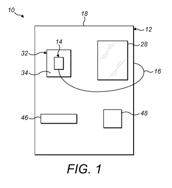
Referring to Figures 1 to 3, there is shown a machine 10 according to a first
embodiment
for producing an aerosol-forming liquid for use in an electrically operated
aerosol-generating
system, such as a smoking system. The machine 10 comprises a main unit 12 and
a testing
mechanism in the form of a handheld electrically operated aerosol-generating
device 14. The
aerosol-generating device 14 is external to the main unit 12 and is coupled to
the main unit by a
flexible electrical cable 16.
The main unit 12 comprises a housing 18 within which is provided a plurality
of reservoirs
20. The reservoirs 20 each contain a liquid component of the aerosol-forming
liquid. The
reservoirs 20 may each contain a different liquid component. Alternatively,
the same liquid
component may be contained in two or more of the reservoirs 20. In this
example, the machine
10 comprises three reservoirs respectively containing nicotine, an aerosol
former and a
CA 02986323 2017-11-17
WO 2017/009002
PCT/EP2016/064079
- 15 -
flavourant, although it will be appreciated that the machine may comprise
fewer or more
reservoirs, for example four, five, six, seven, eight, nine, ten, or more
reservoirs containing
different liquid components of an aerosol-forming liquid.
The main unit 12 includes a mixing mechanism 22 in fluid communication with
each of the
reservoirs 20 by supply tubes 24. Each supply tube 24 includes an electrically
operated valve 26
to control the flow of the liquid component from the reservoir 20 to the
mixing mechanism 22.
The main unit 12 also includes a user interface 28 and a controller 30
connected to the
mixing mechanism 22 and to the user interface 28. The user interface 28 is
operable by a user
to operate the machine, as described below in relation to Figures 3 and 4. In
this example, the
user interface 28 comprises a touch-sensitive display screen, although it
could comprise a display
in combination with a keyboard, keypad, touch-sensitive pad or other similar
input device. The
user interface 28 may also comprise a card payment device (not shown), or
other payment means
for taking payment from a user. The user interface 28 may also comprise a
reader (not shown),
such as an user-ID card reader or passport reader for verifying a user's age.
The controller 30 is connected to the supply valves 26 and is configured to
operate the
valves 26 in response to a testing instruction from a user via the user
interface 28 to dispense to
the mixing mechanism 22 a particular quantity of each liquid component stored
in the reservoirs
according to the desired ratios specified by the user testing instruction. The
mixing mechanism
22 is configured to mix the dispensed quantities of the liquid components to
create an aerosol-
20 liquid test sample for transfer to the aerosol-generating device 14.
The main unit 12 includes a docking station 32 having a docking port 34 for
receiving the
aerosol-generating device. The docking station 32 includes a docking sensor
(not shown)
operable to detect whether the aerosol-generating device 14 is correctly
positioned in the docking
port 34. The docking sensor is connected to the controller 30 and the
controller 30 is arranged
to prevent operation of the machine 10 if the docking sensor detects that the
device 14 is not
correctly positioned in the docking port 34. The device 14 may be held in the
docking port 34 by
a releasable coupling, such as a clip. Alternatively, or in addition, the
docking port 34 may include
a shaped recess arranged to receive and hold at least part of the device 14.
The machine 10 further includes a mouthpiece supply 42 containing a plurality
of
disposable mouthpieces for use with the aerosol-generating device 14 and a
mouthpiece delivery
mechanism 44 connected to the controller 30. The mouthpiece delivery mechanism
44 is
arranged to remove a mouthpiece from the mouthpiece supply 42 and to deliver
the mouthpiece
to a mouthpiece supply port 46 provided in the housing of the main unit 12
based on an instruction
from the controller 30. The mouthpiece can then be removed from the mouthpiece
port 46 by a
user and coupled to the aerosol-generating device 14. The main unit 12 also
includes a
CA 02986323 2017-11-17
WO 2017/009002
PCT/EP2016/064079
- 16 -
mouthpiece disposal port 48 into which used mouthpieces can be placed by a
user for disposal
after use.
In this example, the disposable mouthpieces contained in the mouthpiece supply
42 have
an outer diameter which corresponds to the inner diameter of the outlet at the
downstream end
of the aerosol-generating device 14, so that a mouthpiece from the supply can
be removably
coupled to the outlet by placing the upstream end of the mouthpiece into the
outlet. In other
examples, each mouthpiece may be arranged to couple to the device 14 via a
removable
coupling, such as a screw thread, clip, or bayonet fitting.
Figure 4 is a flow chart showing the operation of the machine 10.
At step Si, the user uses the user interface to activate the machine 10 and
initiate a testing
procedure. At step S2, the machine 10 performs a start-up procedure to check
that a testing
operation can be carried out. For example, during this step, the controller 30
may communicate
with the docking sensor to confirm whether the aerosol-generating device 14 is
correctly
positioned in the docking port 34. The controller 30 may also communicate with
sensors
associated with the reservoirs 20 to confirm whether sufficient levels of e-
liquid component are
stored in the reservoirs 20. If the controller 30 determines during the start-
up procedure that a
testing operation cannot be carried out, an error message is displayed on the
user interface 28,
at step S3, requesting that the user addresses the reason for the halted
testing operation, for
example by ensuring that the device 14 is correctly positioned in the docking
port 34.
At step S4, the user enters user information, including user age information,
via the user
interface 28, for example by allowing a reader in the user interface to read a
user ID, or by entering
the information manually. At step S5, the controller 30 determines whether the
user age
information is valid. If the user age information is not valid, an error
message is displayed on the
user interface 28 at step S6 to inform the user that the testing procedure
will not proceed without
valid user age information.
At step S7, the user uses the user interface to input a testing instruction.
The testing
instruction specifies the desired ratios of each of the liquid components of
the aerosol-forming
liquid which are stored in the reservoirs 20. The testing instruction may be
entered directly by the
user via the user interface 28, for example as described below in relation to
Figure 5.
Alternatively, the testing instruction can be entered indirectly by the user
via the user interface 28
by selecting an e-liquid mix, with predefined component ratios, from a list of
suggested mixes or
from a list of e-liquid mixes associated with the user. For example, the user
interface 28 may
display e-liquid formulations previously tested by the user, or previously
entered by the user using
a remote device and saved to the user's account. As a further alternative, the
machine 10 may
include a cartridge sensor for reading e-liquid formulation information from a
cartridge placed in
CA 02986323 2017-11-17
WO 2017/009002
PCT/EP2016/064079
- 17 -
close proximity to the cartridge sensor by the user, the controller
determining the testing
instruction based on the e-liquid formulation information on the cartridge.
At step S8, the controller 30 determines whether the quantities of liquid
component
specified in the testing instruction are within predetermined limits stored on
the memory. For
example, the controller 30 may determine whether the quantity of nicotine
specified in the testing
instruction exceeds a maximum regulatory limit. Alternatively, or in addition,
the controller 30 may
determine whether the quantities of one or more of the components specified in
the testing
instruction exceed a guideline amount stored on the memory and display a
warning message on
the user interface 28 to inform the user. For example, the controller 30 may
determine whether
the quantity of glycerin exceeds a guideline amount, since too much glycerin
may impair correct
functioning of an aerosol-generating device in which the resulting liquid is
intended for use.
Alternatively, or in addition, the controller 30 may determine whether the
quantities of one or more
e-liquid components specified in the testing instruction would lead to an
undesirable flavour or
flavour combination. If the quantities of e-liquid component specified in the
testing instruction are
outside of predetermined limits, or outside of guideline amounts, an error
message is displayed
on the user interface 28 at step S9 to inform the user and to request
confirmation of the testing
instruction with quantities of e-liquid components that are within
predetermined limits.
At step S10, once the controller 30 has determined that the quantities of e-
liquid
components specified by the user in the testing instruction are within
predetermined limits stored
on the memory, the machine 10 creates the e-liquid test sample according to
the ratios specified
in the testing instruction. During this step, the controller 30 operates the
supply valves 26 in
response to the testing instruction to dispense the quantity of each e-liquid
component specified
in the testing instruction from the reservoir 20 in which it is stored to the
mixing mechanism 22 via
the supply tubes 26 to form the e-liquid test sample.
At step S11, once the e-liquid test sample has been mixed according to the
user testing
instruction, the controller 30 operates the transfer mechanism 36 to select a
disposable heater
assembly from the heater supply 38 and to apply the e-liquid test sample onto
the selected
disposable heater assembly
At step S12, the controller 30 actuates the mouthpiece delivery mechanism 44
to select a
disposable mouthpiece from the mouthpiece supply 42 and to deliver the
selected mouthpiece to
the mouthpiece supply port 46.
At step S13, the controller 30 operates the device 14 to heat the heater
assembly in order
to vapourise the e-liquid test sample applied on the heater assembly to form
an aerosol..
As step S14, the controller 30 displays a message on the user interface 28 to
inform the
user that the test sample has been vapourised and is ready for testing and to
instruct the user to
remove the mouthpiece from the mouthpiece supply port and to place it on the
device 14.
CA 02986323 2017-11-17
WO 2017/009002
PCT/EP2016/064079
- 18 -
At step S15, once the aerosol has been tested, the user deactivates the
testing device 14
via the user interface 28.
At step S16, the controller 30 displays a message on the user interface 28
requesting
feedback on the tested aerosol and instructing the user to remove the
mouthpiece from the
device, dispose of the mouthpiece in the mouthpiece disposal port 48 and to
return the device 14
to the docking station 32. The controller 30 then saves the e-liquid
formulation and feedback
information to the user's registered account and displays a message, at step
S17, asking the user
whether further testing operations are required. If further testing operations
are required, the
controller returns to step S7 and requests that the user enters a testing
instruction via the user
interface 28. If no further testing operations are required, the procedure
ends at step S18.
In some examples the volume of the composition formed in the mixing mechanism
22 from
the components delivered from the reservoirs is greater than is required for
the test sample. In
this case, only a portion of the composition is delivered to the testing
mechanism. The remaining
composition not delivered to the testing mechanism may be later dispensed into
a cartridge, for
example if the user decides to purchase that composition. The remaining
composition not
delivered to the testing mechanism may be held in the machine, either in the
mixing mechanism
22 or in a separate storage unit, and may be dispensed to a subsequent user
for example as a
test sample or in a cartridge.
In a further example of an aspect of the invention, a test sample of the
composition is
delivered from the mixing mechanism 22 to a test cartridge. The volume of
liquid delivered to the
test cartridge may be for example less than about 0.5 ml, for example about
0.1 ml. The cartridge
may comprise a liquid storage container. In other examples, the cartridge may
include other
components for example a heater and optionally a liquid transfer substrate for
transferring liquid
from the liquid storage container to the heater. In some examples, the
cartridge comprises a
cartomiser for an e-cigarette device. The cartridge may for example be a low-
volume cartomiser
which the user may use in combination with their own e-cigarette system to try
a new composition.
The machine for filling the test cartridge may include one or more of the
features described below
in relation to Figures 6 and 7.
Figure 5 is an example selection screen 100 for display on the user interface
28 by which
user may select mix ratios and thereby input a testing instruction. The
selection screen 100
includes a slider bar 102 for each e-liquid component stored in the reservoirs
20. The user can
then increase the quantity of a particular e-liquid component by sliding the
respective slider bar
102 towards the right. The selection screen 100 also includes warning
indicators 104 for one or
more of the e-liquid components. In this example, the warning indicators 104
are each in the form
of a light bulb. The warning indicator 104 for a particular e-liquid component
can be illuminated
CA 02986323 2017-11-17
WO 2017/009002
PCT/EP2016/064079
- 19 -
by the controller 30 if the quantity of that component specified by the user
is outside of a
predetermined limit to provide a warning to the user.
Referring to Figures 6 and 7, there is shown a machine 210 according to a
further
embodiment. The machine 210 is substantially the same as the machine 10
according to the first
embodiment, as described above in relation to Figures 1 to 3, with the
exception that the machine
210 is further arranged to prepare and dispense an aerosol-forming liquid, or
e-liquid, to fill an
empty cartridge for use in an aerosol-generating system. In the below
description, like reference
numerals have been used to designate those parts in common with the machine 10
shown in
Figures 1 to 3.
In addition to the components discussed above in relation to the machine 10
according to
the first embodiment, the main unit 212 of the machine 210 further includes a
dispensing port 250
configured to receive an e-liquid cartridge and a dispensing mechanism 252
associated with the
dispensing port 250 and connected to the controller 230. The dispensing
mechanism 252 is in
fluid communication with the mixing mechanism 222, via a dispensing tube 253
and is configured
to fill a cartridge received in the dispensing port 250 with e-liquid mixed by
the mixing mechanism
222.
The machine 210 further includes a cartridge supply 254, containing a
plurality of
cartridges for use with one or more types of aerosol-generating device, and a
cartridge delivery
mechanism 256 connected to the controller 230. The cartridge delivery
mechanism 256 is
arranged to select and remove a cartridge from the cartridge supply 254 and to
deliver the
selected cartridge to the dispensing port 250 for subsequent filling by the
dispensing mechanism
252. The machine may also include a cartridge marking mechanism (not shown)
for applying
machine-readable e-liquid formulation information to the cartridge, either by
printing the
information onto a label on the cartridge, by applying a printed label on to
the cartridge, or by
applying an RFID tag to the cartridge.
Figure 8 is a flow chart showing the operation of the machine 210.
Steps S1-S18 (not shown), which relate to the testing procedure, are the same
as
described above in relation to Figure 4.
At step S19, the user initiates an e-liquid dispensing operation by inputting
a dispensing
instruction via the user interface 28. The dispensing instruction specifies
the desired ratios of
each of the e-liquid components stored in the reservoirs 220 and the type of
cartridge which is to
be filled by the dispensing operation. The dispensing instruction may be
entered directly by the
user via the user interface 228, for example as described above in relation to
Figures 4 and 5.
Alternatively, the user may enter the dispensing instruction indirectly via
the user interface 228 by
selecting the e-liquid formulation tested during steps S1-S18, or by selecting
an e-liquid mix from
a list of suggested mixes or from a list of e-liquid mixes associated with the
user. For example,
CA 02986323 2017-11-17
WO 2017/009002
PCT/EP2016/064079
- 20 -
the user interface 228 may display e-liquid formulations previously tested by
the user, or
previously entered by the user using a remote device and saved to the user's
account. As a
further alternative, the machine 210 may include a cartridge sensor for
reading e-liquid formulation
information from a cartridge placed in close proximity to the cartridge sensor
by the user, the
controller determining the dispensing instruction based on the e-liquid
formulation information on
the cartridge.
At step S20, the controller 230 determines whether the quantities of e-liquid
component
specified in the dispensing instruction are within predetermined limits stored
on the memory in
the same way as described above in relation to step S8 in Figure 4. If the
quantities of e-liquid
component specified in the dispensing instruction are outside of predetermined
limits, or outside
of guideline amounts, an error message is displayed on the user interface 228
at step S21 to
inform the user and to request confirmation or revision of the dispensing
instruction so that the
specified quantities of e-liquid components are within predetermined limits.
At step S22, the controller 230 queries whether the user has their own
cartridge to be
refilled, or requires a new cartridge to be provided by the machine 210. If
the user has their own
cartridge to be refilled, the controller 230, via the user interface 228,
requests that the user places
the cartridge to be refilled into the dispensing port, at step S23. If a new
cartridge is required, the
controller 230 operates the cartridge delivery mechanism 256 at step S24 to
select and remove
a cartridge from the cartridge supply 254 and to deliver the selected
cartridge to the dispensing
port 250 for subsequent filling by the dispensing mechanism 252.
At step S25, the controller 230 checks whether the cartridge to be filled is
correctly placed
in the dispensing port 250 using one or more sensors (not shown) associated
with the dispensing
port 250. If the cartridge is not correctly positioned in the dispensing port
250, the controller 230
displays an error message on the user interface 228 at step S26 requesting the
user to correctly
place the cartridge in the dispensing port 250. This repeats until the
controller 230 determines
that the cartridge has been correctly positioned in the dispensing port 250.
At step S27, the user operates the user interface 228 to effect payment for
dispensing the
selected e-liquid. If a new cartridge is required, the payment required may be
more than if the
user supplies their own cartridge.
At step S28, the machine 210 creates the e-liquid for filling the cartridge
according to the
ratios specified in the dispensing instruction. During this step, the
controller 230 operates the
supply valves 226 in response to the dispensing instruction to dispense the
desired quantity of
each e-liquid component from the reservoir 220 in which it is stored to the
mixing mechanism 222
via the supply tubes 226. The mixing mechanism 222 then mixes together the e-
liquid
components to form the selected e-liquid.
CA 02986323 2017-11-17
WO 2017/009002
PCT/EP2016/064079
-21 -
At step S29, the dispensing mechanism 252 withdraws the e-liquid from the
mixing
mechanism 222 via the dispensing tube 253 and dispenses the e-liquid into the
cartridge received
in the dispensing port 250 to fill the cartridge.
At step S30, the machine 210 determines whether the cartridge has been filled
with the e-
liquid, either by detecting when a predetermined volume of e-liquid has been
dispensed by the
dispensing mechanism 252 or by detecting the e-liquid level within the
cartridge.
At step S31, after the cartridge has been filled, the controller 230 operates
the cartridge
marking mechanism to apply e-liquid formulation information to the cartridge,
either by printing
the information onto a label on the cartridge, by applying a printed label on
to the cartridge, or by
applying an RFID tag to the cartridge.
The controller 230 then displays an end message on the user interface 228, at
step S32,
indicating that the user may remove the filled cartridge from the dispensing
port 250.
The dispensing operation ends at step S33.
The exemplary embodiments described above illustrate but are not limiting. In
view of the
above discussed exemplary embodiments, other embodiments consistent with the
above
exemplary embodiments will now be apparent to one of ordinary skill in the
art.