Note: Descriptions are shown in the official language in which they were submitted.
MULTI-PURPOSE TOOL
CROSS-REFERENCE TO RELATED APPLICATIONS
[001] This patent application claims priority and benefit from Israeli patent
application
number IL 239432, titled "Multi-Tool Device", filed in the Israeli patent
office on 15 June
2015.
[002] This patent application claims priority and benefit from United States
provisional patent
application number 62/295,148, titled "Multi-Purpose Tool", filed in the
United States patent
office on 15 February 2016.
FIELD
[003] Some embodiments may relate to the field of mechanical tools.
BACKGROUND
[004] Millions of users utilize various types of mechanical tools, in everyday
life as well as
in particular projects. For example, utensils (fork, spoon, knife) are often
used for eating, all
over the world. Similarly, a person may use a screwdriver in order to assemble
a toy, or may
utilize a bottle opener in order to open a sealed bottle of wine.
SUMMARY
[005] The present invention may comprise a multi-purpose tool, or a multiple-
purpose tool.
In some demonstrative embodiments, for example, a multi-purpose tool may
comprise: a
hammer (or hammer-head); a folding or foldable axe; a folding or foldable
spade or shovel (or
spade head, or shovel head); and an assembly to enable a user to selectively
fold and/or unfold
one or more of the tools, or to selectively make one or more of the tools
accessible or
operational while also making one or more other tools non-accessible or non-
operational.
[006] Optionally, the multi-purpose tool may comprise an elongated handle,
which may be
hollow or may comprise an elongated cavity having a led or enclosure or
removable cover.
The elongated cavity within the handle of the multi-purpose tool, may
optionally store one or
more items or tools or inserts, which may be internally stored and secured
within the handle;
and which may be removed or extracted from the handle. Such stored tools may
comprise, for
example: a saw, or a folding saw; a knife; a combination of a knife with a
sheath able to
1
Date Recue/Date Received 2023-01-20
CA 02986374 2017-11-17
WO 2016/203355
PCT/IB2016/053462
protect or store the knife or otherwise cover the blade of the knife; and/or
other suitable
inserts or tools.
[007] The present invention may provide various other advantages and/or
benefits.
BRIEF DESCRIPTION OF THE DRAWINGS
[008] Fig. 1 is a schematic illustration of a side-view of a multi-purpose
tool, in accordance
with some demonstrative embodiments of the present invention.
[009] Fig. 2 is a schematic illustration of a perspective view of the multi-
purpose tool,
demonstrating a shovel component in a partially open state, in accordance with
some
demonstrative embodiments of the present invention.
[0010] Fig. 3 is a schematic illustration of a perspective view of the multi-
purpose tool,
demonstrating the shovel component in a fully open state, in accordance with
some
demonstrative embodiments of the present invention.
[0011] Fig. 4 is a schematic illustration of a perspective view of the multi-
purpose tool,
demonstrating a handle cover and an axe component, in accordance with some
demonstrative
embodiments of the present invention.
[0012] Fig. 5 is a schematic illustration of a perspective view of the multi-
purpose tool,
demonstrating the axe component in an open state, in accordance with some
demonstrative
embodiments of the present invention.
[0013] Fig. 6 is a schematic illustration of a front view of the multi-purpose
tool, in
accordance with some demonstrative embodiments of the present invention.
[0014] Fig. 7 is a schematic illustration of a perspective view of the multi-
purpose tool,
demonstrating a knife component that is connected at an edge of the handle of
the multi-
purpose tool, in accordance with some demonstrative embodiments of the present
invention.
[00151 Fig. 8 is a schematic illustration of a perspective view of the multi-
purpose tool,
demonstrating a knife and a saw, previously housed within the handle of the
multi-purpose
tool and extracted from the handle, in accordance with some demonstrative
embodiments of
the present invention.
[0016] Fig. 9 is a schematic illustration of a side view of a multi-purpose
device,
demonstrating connection means that may be suitable to connect or attach
tool(s) to the outer
side of the multi-purpose device, in accordance with some demonstrative
embodiments of the
present invention.
2
CA 02986374 2017-11-17
WO 2016/203355
PCT/1B2016/053462
[0017] Fig. 10 is a schematic illustration of a side view of the multi-purpose
device, having a
knife component connected thereto, in accordance with some demonstrative
embodiments of
the present invention.
[0018] Fig. 11 is a schematic illustration of a perspective view of the multi-
purpose device,
demonstrating the knife component, in accordance with some demonstrative
embodiments of
the present invention.
[0019] Fig. 12 is a schematic illustration of a perspective view of the multi-
purpose device,
demonstrating a saw component connected thereto, in accordance with some
demonstrative
embodiments of the present invention.
[0020] Figs. 13A-13B are schematic illustrations of perspective views of a
multi-purpose
apparatus, shown in a closed position, in accordance with some demonstrative
embodiments
of the present invention.
[0021] Figs. 14A-14B are schematic illustrations of perspective views of the
multi-purpose
apparatus, demonstrating its axe in an open position, in accordance with some
demonstrative
embodiments of the present invention.
[0022] Fig. 14C is a schematic illustration of a side view of the multi-
purpose apparatus,
demonstrating the axe in an open position, in accordance with some
demonstrative
embodiments of the present invention.
[0023] Fig. 14D is a schematic illustration of a top view of the multi-purpose
apparatus,
demonstrating the axe in an open position, in accordance with some
demonstrative
embodiments of the present invention.
[0024] Figs. 15A-15B are schematic illustrations of perspective views of the
multi-purpose
apparatus, demonstrating its shovel in an open position at 90 degrees relative
to the long
dimension of the elongated handle, in accordance with some demonstrative
embodiments of
the present invention.
[0025] Fig. 15C is a schematic illustration of a side view of the multi-
purpose apparatus,
demonstrating the shovel in an open position at 90 degrees relative to the
long dimension of
the elongated handle, in accordance with some demonstrative embodiments of the
present
invention.
[0026] Fig. 15D is a schematic illustration of a top view of the multi-purpose
apparatus,
demonstrating the shovel in an open position at 90 degrees relative to the
long dimension of
the elongated handle, in accordance with some demonstrative embodiments of the
present
invention.
3
CA 02986374 2017-11-17
WO 2016/203355
PCT/1B2016/053462
[0027] Fig. 15E is a schematic illustration of a bottom view of the multi-
purpose apparatus,
demonstrating the shovel in an open position at 90 degrees relative to the
long dimension of
the elongated handle, in accordance with some demonstrative embodiments of the
present
invention.
[0028] Figs. 16A-16B are schematic illustrations of perspective views of the
multi-purpose
apparatus, demonstrating the shovel in an open position at 180 degrees
relative to the long
dimension of the elongated handle, in accordance with some demonstrative
embodiments of
the present invention.
[0029] Figs. 17A-17F are schematic illustrations of side-views of the multi-
purpose
apparatus in a closed position, in accordance with some demonstrative
embodiments of the
present invention.
[0030] Figs. 18A-18C are schematic illustrations of the axe (detached or dis-
assembled from
the multi-purpose apparatus), in accordance with some demonstrative
embodiments of the
present invention.
[0031] Figs. 18D-18F are schematic illustrations of another implementation of
the axe
(detached or dis-assembled from the multi-purpose apparatus), in accordance
with some
demonstrative embodiments of the present invention.
[0032] Figs. 19A-19D are schematic illustrations of a head component of the
multi-purpose
apparatus, in accordance with some demonstrative embodiments of the present
invention.
[0033] Figs. 20A-20D are schematic illustrations of a lock component of the
multi-purpose
apparatus, in accordance with some demonstrative embodiments of the present
invention.
[0034] Figs. 21A-21B are schematic illustrations of the shovel (detached or
dis-assembled
from the multi-purpose apparatus), in accordance with some demonstrative
embodiments of
the present invention.
[0035] Figs. 22A-22D are schematic illustrations of the elongated handle of
the multi-
purpose apparatus, in accordance with some demonstrative embodiments of the
present
invention.
[0036] Fig. 23A is a schematic illustration of a saw in an open position, in
accordance with
some demonstrative embodiments of the present invention.
[0037] Fig. 23B is a schematic illustration of the saw in a closed or folded
position, in
accordance with some demonstrative embodiments of the present invention.
[0038] Figs. 24A-24C are schematic illustrations of a knife, in accordance
with some
demonstrative embodiments of the present invention.
4
CA 02986374 2017-11-17
WO 2016/203355
PCT/1B2016/053462
[0039] Figs. 25A-25D are schematic illustrations of a sheath, in accordance
with some
demonstrative embodiments of the present invention.
[0040] Figs. 26A-26C are schematic illustrations of an insert, which is a
combination of the
sheath holding the knife, in accordance with some demonstrative embodiments of
the present
invention.
[0041] Figs. 27A-27B are schematic illustrations of the multi-purpose
apparatus,
demonstrating also the insert and the saw extracted from the elongated handle,
in accordance
with some demonstrative embodiments of the present invention.
[0042] Fig. 28A is a schematic illustration of a perspective view of a kit of
components,
which may be utilized in order to assemble or construct the multi-purpose
apparatus, in
accordance with some demonstrative embodiments of the present invention.
[0043] Fig. 28B is a schematic illustration of a side view of the kit of
components, which
may be utilized in order to assemble or construct the multi-purpose apparatus,
in accordance
with some demonstrative embodiments of the present invention.
[0044] Figs. 29A-29D are schematic illustrations of another multi-purpose
device, shown in a
closed axe position, in accordance with some demonstrative embodiments of the
present
invention.
[0045] Figs. 29E-29H are schematic illustrations of that other multi-purpose
device, shown in
an open axe position, in accordance with some demonstrative embodiments of the
present
invention.
DETAILED DESCRIPTION OF SOME DEMONSTRATIVE EMBODIMENTS
[0046] The present invention relates to mechanical tools. More particularly,
the invention
relates to a multi-tool device that combines several tools into one integrated
device.
[0047] The use of tools is required in many occasions, whether at home or
outdoors, but if a
person needs to carry tools with him for an outdoors activity it is highly
important to take
under consideration the weight and volume of the tools that he or she carries
with him/her.
[0048] Common outdoor activities that require the use of tools are, for
example, camping,
hunting, fishing, hiking, and climbing. There is also a need for tools in
military, law
enforcement, and first responder activities. The tools that are usually
suitable for such needs
are basic tools, such as a knife, saw, hammer, ax or axe or hatchet, and
shovel or spade,
which can be used for setting up tents or other forms of shelters, cutting
different things like
food or ropes or wood, and/or performing other suitable operations.
CA 02986374 2017-11-17
WO 2016/203355
PCT/1B2016/053462
[0049] The cost of all necessary tools is often considerable and when planning
an outdoor
activity, the cumulative weight and volume of all tools can be an obstacle,
since in some
activities a user has to carry his equipment in a backpack. Even when
traveling with a
vehicle, a heavy and high-volume load can be a burden, and using separate
tools can be
inconvenient when searching for a specific tool. For those reasons, users
sometimes choose to
carry only some of the necessary tools, which can reduce the duration of stay
and/or make it
more difficult to manage outdoors.
[0050] Therefore, it is an object of the present invention to provide one
integrated device that
combines different types of tools, which can be easily carried and used, and
is relatively
lightweight. Other objects and advantages of the invention will become
apparent as the
description proceeds.
[0051] The present invention comprises a device comprising a plurality of
tools operable in
connection with a central structure, wherein all or part of the tools can be
housed within the
central structure, or part of the tools can be attached or attachable to its
external surface, and
wherein housed tools are suitable to be partially or fully pulled out of said
structure and can
be used separately or integrally with the structure, and wherein said
structure is provided with
connection means, suitable to be connected to tools at its external surface.
The connection
means can be, for example, fasteners and protrusions that are suitable to be
attached to
different structures that are provided with compatible parts, like holes and
clips.
[0052] Tools that are suitable to be used in the invention can be for
instance, shovel or spade,
ax or axe, knife, saw, hammer, etc. The central structure can also have a
portion that is
suitable to be used as a hammer head. Each tool can be connected to the
central structure be
an axis, such as a rotational axis, or by any other known connection means,
and the central
structure can be provided with stopping means, suitable to constrain the
movement of tools in
relation to the structure.
[0053] The device may further comprise slits or cavities, suitable to house or
store tools;
and/or grip points or attachment points, suitable to hold tools within the
slits until a suitable
force is applied to displace them. The grip points may be suitable to provide
tools the ability
to rotate around them.
[0054] The tools may comprise holes and/or clips that are suitable to be
connected to the
connection means of the central structure, and they can also be foldable.
[0055] The present invention provides a device that comprises a plurality of
tools operable in
connection with a central structure. By the term "operable" it is meant that
all or part of the
tools can be housed within said central structure, or part of the tools can be
attached or
6
CA 02986374 2017-11-17
WO 2016/203355
PCT/1B2016/053462
attachable to its external surface. The invention provides a relatively
compact device that
comprises basic tools; it provides significant advantages, such as a
lightweight tool collection
with relatively low volume, which makes it easier to carry than other known
devices.
[0056] Fig. 1 is a side view of a device, according to one embodiment of the
invention,
showing the central structure 101, which is basically the skeleton of the
device that comprises
or is connected to different tools. Central structure 101 comprises two main
parts, the lower
part 102, which can also be referred to as "the handle", which is suitable to
house relatively
narrow tools, or any type of tools that will fit handle 102, and the upper
part 103, which is
suitable to house additional and/or wider tools. Exemplary tools will be
illustrated in the
following description.
[0057] Fig. 1 also shows a side view of a shovel 104, in a folded state,
wherein shovel 104 is
juxtaposed to central structure 101. Shovel 104 is connected to structure 101
by a rotational
axis 105 and can be moved to an open state by pulling it so as to cause it to
rotate around axis
105, as illustrated in Figs. 2 and 3.
[0058] Another part of structure 101 is the edge 106, which can be used as a
hammer. Handle
102 can be used as a hammer handle, and edge 106 can be used as the tip of a
hammer.
[0059] Fig. 2 is a perspective view of the device of Fig. 1, showing shovel
104 in a partially
open state, and Fig. 3 is also a perspective view of the device of Fig. 1, in
which shovel 104 is
in a fully open state. As shown in Fig. 2, upper part 103 comprises a stopping
mechanism
201, which, in this particular illustrative embodiment of the invention, is a
stair-like structure,
suitable to prevent shovel 104 from passing a predetermined point. The
location of stopping
mechanism 201 determines the limit of the rotation of shovel 104. Fig. 3 shows
that stopping
mechanism 201 limits the movement of shovel 104 so it will not move further
than the point
where shovel 104 is in line with central structure 101 when it is in an open
state
[0060] The location of stopping mechanism 201 can also be at any other desired
location that
will serve the purpose of limiting the movement of shovel 104 at a desired
location. Central
structure 101 can also comprise additional stopping mechanisms that will
provide the ability
to choose each time up to what extent one chooses to open shovel 104, since
different
activities may require different uses of shovel 104, and it provides a user
the ability to adjust
shovel 104 to his convenience.
[0061] Fig. 2 also shows slits 202 and 203 along handle 102, which are
suitable for housing
long and narrow tools. Such slits can be of any length, up to the length of
handle 102, and
handle 102 can comprise any number of slits of different dimensions that fits
its volume.
Handle 102 also comprises grip points 204 and 205 that are suitable to hold in
place tools that
7
CA 02986374 2017-11-17
WO 2016/203355
PCT/1B2016/053462
are located inside slits 202 and 203. Grip points 204 and 205 can be of any
type and shape of
known gripping means, for example, they can consist of tightening means that
can hold tools
in place, and they can be ether noticeable, flat, or positioned in the
internal part of handle
102.
[0062] Tools that are housed within slits 202 and 203 can be pulled out of
them and used
independently (as will be shown in Fig. 8), but they can also be used as a
pocketknife-like
device, and for that purpose grip points 204 and 205 can be designed to hold
tools and allow
their rotation, as in a pocketknife.
[0063] Slits 202 and 203 can be covered, as shown in Fig. 4, where cover 401
is connected to
handle 102. The cover of slits 202 and 203 protects them and the tools that
are located within
them. Cover 401 can be very important when engaging in outdoor activity that
can cause the
device to be exposed to dirt, dust, sand or the like agents that may adversely
affect the
operation of the device. Slits 202 and 203 and cover 401 can also be provided
on both sides
of handle 102 (not shown), depending on the tools that need to be housed
within handle 102
and their location.
[0064] Fig. 4 also shows an ax 402 in its folded state, located inside a large
slit 403 at the
upper part 102 of structure 101. Large slit 403 can also be covered, as slits
202 and 203, for
the same purpose of protecting the components of the device. Ax 402 is
connected to upper
part 103 by a rotational axis (not shown) that provides it the ability to be
opened, similarly to
shovel 104. Fig. 5 shows ax 402 in an open state, which can be achieved by
pulling ax 402,
thus allowing it to rotate around its axis.
[0065] Fig. 6 is a front view of the device of Fig. 1, showing the front of
shovel 104.
According to this embodiment, the width of the device is essentially
determined by the width
of shovel 104, which is relatively narrow, thus presenting the great advantage
of a low-
volume device. The volume of the device can also be changeable by telescopic
means, for
example, lower part 102 can be inserted into upper part 103 by telescopic
means in order to
reduce the volume, or alternatively, both parts 102 and 103 can be connected
to each other by
an axis that allows folding the device. Such volume- or length-controlling
means can also be
used for the purpose of extending the length of handle 102, which can be
useful when trying
to reach remote targets. Even if the device is not foldable, it is still
relatively short because
each tool is in close juxtaposition to, or housed within central structure
101, when not in use.
The length of an illustrative device, according to the embodiment of Fig. 1,
is only about 45
cm.
8
CA 02986374 2017-11-17
WO 2016/203355
PCT/1B2016/053462
[0066] Fig. 6 also shows two exemplary tools that are housed inside handle
102. The
exemplary tools are knife 601 and saw 602. As shown in Fig. 7, knife 601 can
be positioned
at the bottom edge of handle 102. The positioning of knife 601 can be
performed by pulling
out knife 601 from handle 102 and inserting its lower section into a suitable
slit at the bottom
part of handle 102, but it can also be performed by any other mechanical means
that will
provide the possibly to position knife 601 at the bottom of handle 102, and
the shape of slit
202 can be designed accordingly.
[0067] Fig. 8 shows knife 601 and saw 602 separately from handle 102. Saw 602
is shown in
Fig. 6 in a folded state, and in Fig. 8 it is shown that the blade 801 of saw
602 is connected to
its base 802 by axis 803, thus allowing saw 602 to be folded. Of course, knife
601 can also be
foldable by providing it with a similar axis. In the particular embodiment of
Fig. 8 knife 601
and saw 602 comprise holes, e.g. 804 and 805, and clips, e.g., 806, 807, 808,
and 809, all
which are suitable to provide the ability to connect knife 601 and saw 602 to
external surfaces
of structure 101 or to any other suitable structures.
[0068] Fig. 9 is a side view of the device, according to another embodiment of
the invention,
illustrating an exposed upper part (without a cover) showing connection means
such as
protrusion 901, and fasteners 902 and 903, which are suitable to connect to
tools like knife
601 and saw 602 by connection means like holes 804 and 805 and clips 806, 807,
808, and
809. Fig. 10 is a side view of the device of Fig. 9, where knife 601 is
connected to the device
of Fig. 9 by protrusion 901 and fasteners 902 and 903. Such connection
provides the ability to
extend the distance at which knife 601 can be used by holding the device by
its handle.
[0069] Fig. 11 shows knife 601 connected to the device of Fig. 9, indicated by
numeral 1101,
where the upper part of device 1101 is provided with a cover 1102, and Fig. 12
shows saw
602 connected to device 1101 (which is also provided with cover 1102). The
connection of
tools to the device at the outer side of the structure can be performed not
only by protrusions
and fasteners as shown in Fig. 10, but also by any other mechanical connection
means, such
as a rails or bands.
[0070] Although for the sake of brevity the description refers only to a
shovel, an ax, a
hammer, a knife, and a saw, the device can comprise in the alternative or in
addition, many
other tools, and the user can also decide which tools he wishes to carry with
him. Nothing in
the above description should be interpreted as a limitation to the kind of
tool that can be used
in conjunction with the invention.
[0071] The device of the invention may be highly versatile and/or modular,
thus is suitable
for many types of activities. The combination of a large number of tools in a
single device is
9
CA 02986374 2017-11-17
WO 2016/203355
PCT/IB2016/053462
very cost-efficient. Another significant advantage is the fact that a
relatively small device can
be used in many forms, which saves users the trouble of carrying heavy and
high-volume
tools instead.
[0072] The present invention may provide a device comprising a plurality of
tools operable
in connection with a central structure, wherein all or part of the tools can
be housed within
said central structure, or part of the tools can be attached or attachable to
its external surface,
and wherein housed tools are suitable to be partially or fully pulled out of
said structure and
can be used separately or integrally with said structure, and wherein said
central structure is
provided with connection means, suitable to be connected to tools at its
external surface.
[0073] In some embodiments, one of the tools or units of the device is a
shovel or a spade or
a knife or a saw or a hammer or an axe. In some embodiments, some or all of
these units are
comprised in the device or mounted on the device.
[0074] In some embodiments, at least one of the above-mentioned units is
connected to the
structure by a rotational axis. In some embodiments, the device comprises a
stopping
mechanism, suitable to constrain the movement of tools in relation to the
structure.
[0075] In some embodiments, the device comprises comprising slits, suitable to
house tools.
[0076] In some embodiments, the device comprises grip points, suitable to hold
tools within
the slits until a suitable force is applied to displace them. In some
embodiments, the grip
points provide tools the ability to rotate around them.
[0077] In some embodiments, one of the tools is an ax or axe. In some
embodiments, the ax
is connected to the central structure by a rotational axis. In some
embodiments, the central
structure has a portion that is suitable to be used as a hammer head. In some
embodiments,
one of the tools is a knife or a saw. In some embodiments, the knife comprises
holes and/or
clips that are suitable to be connected to the connection means of the central
structure. In
some embodiments, the saw comprises holes and/or clips that are suitable to be
connected to
the connection means of the central structure. In some embodiments, the knife
is foldable. In
some embodiments, the saw is foldable.
[0078] The present invention may comprise a multi-purpose tool, or a tool
assembly, or a
multi-unit or multiple-unit tool, which may be used for various purposes
(e.g., hiking,
outdoor survival, military use, law enforcement, first responders, or the
like).
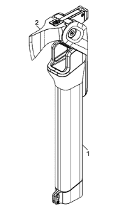
[0079] Figs. 13A-13B are schematic illustrations of perspective views of a
multi-purpose
apparatus 1, shown in a closed position, in accordance with some demonstrative
embodiments of the present invention. Multi-purpose apparatus I may comprise,
for
example, a folding axe 2, a folding shovel 3, a hammer-head 4, and an
elongated handle 7.
CA 02986374 2017-11-17
WO 2016/203355
PCT/1B2016/053462
[0080] Figs. 14A-14B are schematic illustrations of perspective views of the
multi-purpose
apparatus 1, demonstrating the axe 2 in an open position, in accordance with
some
demonstrative embodiments of the present invention.
[0081] Fig. 14C is a schematic illustration of a side view of the multi-
purpose apparatus 1,
demonstrating the axe 2 in an open position, in accordance with some
demonstrative
embodiments of the present invention.
[0082] Fig. 14D is a schematic illustration of a top view of the multi-purpose
apparatus 1,
demonstrating the axe 2 in an open position, in accordance with some
demonstrative
embodiments of the present invention.
[0083] Figs. 15A-15B are schematic illustrations of perspective views of the
multi-purpose
apparatus 1, demonstrating the shovel 3 in an open position at 90 degrees
relative to the long
dimension of the elongated handle 7, in accordance with some demonstrative
embodiments of
the present invention.
[0084] Fig. 15C is a schematic illustration of a side view of the multi-
purpose apparatus 1,
demonstrating the shovel 3 in an open position at 90 degrees relative to the
long dimension of
the elongated handle 7, in accordance with some demonstrative embodiments of
the present
invention.
[0085] Fig. 15D is a schematic illustration of a top view of the multi-purpose
apparatus 1,
demonstrating the shovel 3 in an open position at 90 degrees relative to the
long dimension of
the elongated handle 7, in accordance with some demonstrative embodiments of
the present
invention.
[0086] Fig. 15E is a schematic illustration of a bottom view of the multi-
purpose apparatus 1,
demonstrating the shovel 3 in an open position at 90 degrees relative to the
long dimension of
the elongated handle 7, in accordance with some demonstrative embodiments of
the present
invention.
[0087] Figs. 16A-16B are schematic illustrations of perspective views of the
multi-purpose
apparatus 1, demonstrating the shovel 3 in an open position at 180 degrees
relative to the long
dimension of the elongated handle 7, in accordance with some demonstrative
embodiments of
the present invention.
[0088] Figs. 17A-17F are schematic illustrations of side-views of the multi-
purpose
apparatus 1 in a closed position, in accordance with some demonstrative
embodiments of the
present invention.
[0089] Figs. 18A-18C are schematic illustrations of the axe 2 (e.g., detached
or dis-
assembled from the multi-purpose apparatus 1), in accordance with some
demonstrative
11
CA 02986374 2017-11-17
WO 2016/203355
PCT/1B2016/053462
embodiments of the present invention. The axe 2 may have holes or apertures,
or connecting
elements, which may enable the axe to pivot by 90 degrees, from being in a
first position
(e.g., in which the cutting edge of the axe is hidden or covered), to being in
a second position
(e.g., in which the cutting edge of the axe is exposed, or is operational, or
is facing
outwardly). The axe 2 may be implemented as (or may be) a hatchet, a hatchet-
head, an axe-
head, or other suitable striking tool having a sharp blade which may be used,
for example, to
cut wood or to split wood or for similar purposes. Accordingly, the terms
"axe" or "ax" as
used herein, may include such hatchet or axe-head or other suitable striking
tool.
[0090] In some embodiments, the axe 2 may be implemented as a single,
monolithic, unit or
element, which cannot be disassembled into smaller sub-units; thereby
providing to such unit
sufficient strength, endurance, dexterity and/or rigidity in order to allow
such unit to remain
intact while it is used for striking an object (e.g., wood). In other
embodiments, optionally,
the axe 2 may be implemented by using two or more sub-units or elements, which
may be
tightly or rigidly connected together or attached together or otherwise
interconnected or
secured to each other, while still providing the suitable strength, endurance,
dexterity and/or
rigidity to the axe 2.
[0091] Figs. 18D-18F are schematic illustrations of exploded views of an axe
50 (e.g.,
detached or dis-assembled from the multi-purpose apparatus 1), in accordance
with some
demonstrative embodiments of the present invention. Axe 50 may be generally
similar to axe
2 discussed above. However, while axe 2 may be a single, monolithic unit, axe
50 may be
implemented as an assembly of two or more elements or sub-units. In a
demonstrative
example as shown, axe 50 may comprise an axe-blade 51 and an axe-base 52,
which may be
interconnected or otherwise attached to each other by using one or more
connection
mechanisms or attachment mechanism, such as by using a screw 53 or other
suitable
connection elements (e.g., bonding, gluing, screw with bonding, screw with
gluing, male-
female connection mechanism, screw with threading mechanism, or the like).
[0092] The implementation of axe 50 as an assembly of multiple sub-units may
have various
advantages or benefits. In a demonstrative embodiment, this may enable
efficient and/or
easier sharpening of the axe-blade 51. Additionally or alternatively, the axe-
base 52 may
have a suitable contour or structure such that it may split or separate or
divide a wooden
object (or other breakable object) into two or more pieces, while also
protecting or hiding
other units of the apparatus 1 (e.g., shovel 3) from getting in touch with
such object or its
pieces. Additionally or alternatively, the separation of axe 50 into two (or
more) sub-units
may enable to manufacture the two (or more) sub-units from two (or more)
different
12
CA 02986374 2017-11-17
WO 2016/203355
PCT/1B2016/053462
materials, having different characteristics or functions: for example, the axe-
base 52 may be
formed of Titanium in order to be lightweight yet rigid, whereas the axe-blade
51 may be
forged or steeled or formed as a stainless steel which may be strengthened and
hardened in
order to remain sharp for a long period of time.
[0093] Even though other suitable material(s) may be used, it is noted that
the Applicants
have realized that the unique assembly of the axe 50 from two interconnected
units, and the
unique selection of Titanium for the axe-base 52 and stainless steel for the
axe-blade 51, may
provide a unique and non-trivial features combination of rigidity and
endurance, as well as
enabling the axe 50 to be lightweight and to remain sharp over time.
[0094] Figs. 19A-19D are schematic illustrations of a head component 9 of the
multi-purpose
apparatus 1, in accordance with some demonstrative embodiments of the present
invention.
The head component 9 may be connected or attached to a top side of the
elongated handle 7.
The head component 9 may hold in place one or more tools of the multi-purpose
apparatus 1,
such as the axe 2 and/or the shovel 3. The head component 9 may integrally
comprise or may
monolithically comprise one or more tools, such as the hammer-head 4.
Optionally, the head
component 9 may comprise, or may be connected to, hinges and/or axis
components and/or
pivoting elements, which may enable selective folding and unfolding (or
insertion and
extraction; or collapsing and un-collapsing; or exposing and hiding) of one or
more of the
tools of the multi-tool apparatus 1. Optionally, the pivoting may be gradual
or may utilize
stoppers to enable full extension (e.g., of the axe 2), full extension (e.g.,
holding the shovel 3
at 180 degrees relative to the elongated handle 7), partial extension (e.g.,
holding the shovel 3
at 90 degrees relative to the elongated handle 7), or the like. The head
component 9 may
comprise hinges or axis or connectors that may allow the axe 2 and/or the
shovel 3, to
selectively pivot by 90 degrees or by 180 degrees, or to selectively be
exposed and
operational (or, hidden or covered and non-operational); or to pivot between
being stored
securely, to being exposed outwardly and operational.
[00951 Figs. 20A-20D are schematic illustrations of a lock component 8 of the
multi-purpose
apparatus 1, in accordance with some demonstrative embodiments of the present
invention.
The lock component 8 may operate, optionally in conjunction with the head
assembly 9, in
order to selectively fold and/or unfold one or more of the tools, and/or in
order to hold in
place or otherwise secure one or more of the tools of the multi-purpose
apparatus 1.
[0096] Figs. 21A-21B are schematic illustrations of the shovel 3 (e.g.,
detached or dis-
assembled from the multi-purpose apparatus 1), in accordance with some
demonstrative
embodiments of the present invention. The shovel 3 may have holes or
apertures, or
13
CA 02986374 2017-11-17
WO 2016/203355
PCT/1B2016/053462
connecting elements, which may enable the shovel 3 to pivot by 90 degrees,
from being in a
first position (e.g., in which the digging edge of the shovel 3 is hidden or
covered), to being
in a second position (e.g., in which the cutting edge of the shovel 3 is
exposed, or is
operational, or is facing outwardly); and optionally, to even pivot by an
entire 180 degrees, or
by an additional 90 degrees, such that the shovel 3 may be at 180 degrees
angle relative to its
original stored or secured position, now facing outwardly and away from the
top-side of the
elongated handle 7. Accordingly, the shovel 3 may have three positions: a zero
degree
position of being stored securely; a 90 degree position of being exposed
perpendicularly to
the elongated handle 7; and a 180 degree position of being exposed parallel to
(or as an
extension to) the elongated handle 7.
[0097] Figs. 22A-22D are schematic illustrations of the elongated handle 7 of
the multi-
purpose apparatus 1, in accordance with some demonstrative embodiments of the
present
invention. The elongated handle 7 may be hollow or partially-hollow and may
comprise an
elongated cavity which may store or hold therein one or more items, such as an
insert 12; a
cover 18 may be operated by the user to close or open the cavity.
[0098] Fig. 23A is a schematic illustration of a saw 13 in an open position,
in accordance
with some demonstrative embodiments of the present invention. Fig. 23B is a
schematic
illustration of saw 13 in a closed or folded position, in accordance with some
demonstrative
embodiments of the present invention. Saw 13 may be inserted into (and
extracted from) the
cavity of the elongated handle 7. Optionally, saw 13 may be connected or
attached or
secured to the elongated handle 7, and/or an external surface or edge or point
of the multi-
purpose apparatus 1, in order to provide an improved or extended grip on saw
13, and/or in
order to enable the user to reach with the saw 13 towards a remote target
(e.g., to cut a high
branch of a tree).
[0099] Figs. 24A-24C are schematic illustrations of a knife 14, in accordance
with some
demonstrative embodiments of the present invention. Knife 14 may be inserted
into (and
extracted from) the cavity of the elongated handle 7. Optionally, knife 14 may
be connected
or attached or secured to the elongated handle 7, and/or an external surface
or edge or point
of the multi-purpose apparatus 1, in order to provide an improved or extended
grip on knife
14, and/or in order to enable the user to reach with the knife 14 towards a
remote target.
[00100] Figs. 25A-25D are schematic illustrations of a sheath 15, in
accordance with
some demonstrative embodiments of the present invention. Sheath 15 (or other
or similar
blade-protector or blade-cover, or knife-protector or knife-cover) may be
inserted into (and
extracted from) the cavity of the elongated handle 7. Sheath 15 may hold or
secure the knife
14
CA 02986374 2017-11-17
WO 2016/203355
PCT/IB2016/053462
14, or other suitable blade or saw or sharp item. Optionally, Sheath 15 may
operate to both
(i) hold therein the knife 14, and (ii) be connected to or be held by the
folded saw 13. Other
suitable arrangements may be used.
[00101] Figs. 26A-26C are schematic illustrations of an insert 16, which
may be a
combination of sheath 15 holding therein knife 14, in accordance with some
demonstrative
embodiments of the present invention. Insert 16 may be inserted into (and
extracted from)
the cavity of the elongated handle 7.
[00102] Figs. 27A-27B are schematic illustrations of the multi-purpose
apparatus 1,
demonstrating also the insert 16 and the saw 13 extracted from the elongated
handle 7, in
accordance with some demonstrative embodiments of the present invention.
[00103] Fig. 28A is a schematic illustration of a perspective view of a
kit 17 of
components, which may be utilized in order to assemble or construct the multi-
purpose
apparatus 1, in accordance with some demonstrative embodiments of the present
invention.
[00104] Fig. 28B is a schematic illustration of a side view of the kit 17
of components,
which may be utilized in order to assemble or construct the multi-purpose
apparatus 1, in
accordance with some demonstrative embodiments of the present invention.
[00105] In a demonstrative embodiment, a central member is an elongated
member
having an elongated cavity. The top side of the central member may have a top-
side
assembly element, which may mount and/or store multiple upper-area units, for
example, an
axe (or ax), a shovel (or spade), and a hammer (or hammer head). These three
units may be
mounted on, or attached to, the top-side assembly element, which may allow
each one of
these three units to pivot or to rotate or to spin, in a selective and/or
controlled manner, and to
stop at one or more particular pivot points; for example, using an axis,
hinges, stoppers, or
other pivoting mechanism(s). This may allow, for example, folding and
unfolding of the axe
unit; folding and unfolding of the hammer unit; and folding and unfolding of
the shovel unit
between two positions (e.g., folded and unfolded) or among multiple positions
(e.g., folded;
unfolded at 90 degrees relative to the central member; unfolded at 180 degrees
relative to the
central member; unfolded at 45 or 135 or 225 or 270 degrees relative to the
central member;
unfolded at other angle or slanting relative to the central member).
[00106] The cavity inside the central member may be hollow and may store,
and may
hold in place, one or more additional tools or units, which may be referred to
as "internal
units" or a "magazine", and may be extracted or pulled-out or spilled-out from
within the
cavity. For example, the bottom-side of the central member may have a door or
a cover,
which may be taken apart and put back, or which may pivot by using an axis or
hinge,
CA 02986374 2017-11-17
WO 2016/203355
PCT/1B2016/053462
thereby allowing the user to access the content stored within the cavity. The
cover may
optionally comprise a locking mechanism, or other safety feature, to prevent
non-desired or
unintentional opening of the cover or unintentional spillage of the content of
the cavity.
[00107] In a demonstrative embodiment, the internal units stored within
the cavity,
may be or may comprise: a saw; a knife; and optionally a sheath or cover for
the knife; and
optionally a sheath or cover for the saw. It is noted that these are only some
demonstrative
and non-limiting examples to internal tools which may be stored within the
central member
or the magazine; and other suitable tools or accessories may be stored
therein.
[00108] In some embodiments, the tool may enable the user to utilize each
one of the
five units (or other number of units), at the same level of quality of an
independent unit or
discrete unit. The multiple units or some of them may be connected to (or
stored within) the
same and the single central member, which may operate in a multi-purpose
manner as a
carrying handle for the tool, as a working handle for utilizing each unit, and
as a storage unit
to store the internal units.
[00109] It is noted that no conventional tool has both a saw and a knife
stored together
within the same central cavity or within the same handle of the tool. In some
embodiments,
the saw may be a full, standard-size saw having a blade length of 6 or 8 or 10
or 12 or 15
inches, or of at least 6 or 8 or 8 or 10 or 12 or 15, inches, optionally being
a replaceable
blade. It is clarified that these are only non-limiting examples, and other
suitable sizes or
dimensions may be used.
[00110] It is noted that no conventional tool has a saw and a knife and a
sheath (e.g.,
for protecting the knife and/or for carrying the knife on the body once the
knife is extracted
from the cavity) that are all stored together within the same central cavity
or within the same
handle of the tool.
[00111] The tool of the present invention may be lightweight, for example,
by utilizing
one or more materials that are strong and rigid yet lightweight (e.g.,
titanium, aluminum,
steel), and may have a small or reduced form-factor or footprint.
[00112] In some embodiments, the external units or the upper-side units,
such as the
axe and the shovel and the hammer-head, are particularly arranged or mounted
or assembled
relative to the upper-side assembly element and/or relative to the elongated
central member,
in a way that enables the central member to operate as a working handle for
utilizing each
one of them; and in a way that enables each one of these three units to
operate independently
and without being obstructed, partially or entirely or at all, by the location
or the existence of
16
CA 02986374 2017-11-17
WO 2016/203355
PCT/1B2016/053462
the other external units; for example, such that the axe may be fully
operational without being
hindered or obstructed or blocked by the shovel unit which is located nearby
or behind it.
[00113] The upper-side assembly element may optionally comprise a locking
mechanism which may lock in place, in the alternate, either the axe in an open
state, or the
shovel in an open state (or both of them in a folded or closed state). The
locking mechanism
may alternately lock the axe or the shovel, and the upper-side region of the
tool is suitable for
operating under the pressure and forces that are expected from each discrete
unit on its own.
The locking mechanism may further enable the locking into place of units that
are not in use,
in order to secure them and to avoid their detachment or their becoming loose;
and further
enables the locking into place of a unit that is being used, in order to
provide the rigidity or
rigidness or sturdiness that are required for the efficient and safe operation
of each such unit.
[00114] In some embodiments, the cover of the central member may be secured
or held
in place via a safety-catch or safety-pin or other securing mechanism that
prevents accidental
or unintentional opening of the central member during the actual usage of the
multi-purpose
tool; for example, securely preventing non-desired opening of the central
member when a
user utilizes the tool as an axe or as a hammer or as a shovel or spade. In
some embodiments,
the safety-catch or other securing mechanism of the bottom-side cover of the
central member,
may be held in place manually or automatically once the multi-purpose tool is
unfolded
and/or utilized in conjunction with one of the upper-side units (e.g., axe,
hammer, shovel or
spade).
[00115] In some embodiments, the tool may be structured in a manner that
spreads or
distributes weight generally evenly across multiple regions of the tool;
and/or in a manner
that causes the center of gravity of the tool to enable safe and efficient
operation of each unit
when that unit is in an open (or unfolded) position.
[00116] In some embodiments, the axe may have its own locking / unlocking
mechanism relative to the upper-side assembly member, and the shovel may have
its own,
different, locking / unlocking mechanism relative to the upper-side assembly
member. In
other embodiments, a single locking member (e.g., "back lock") in the upper-
side assembly
member, may secure, or may lock / unlock in the alternate, both the axe and
the shovel;
thereby reducing the weight and/or the form factor of the tool, and also
reducing the number
of parts or components of the tool (e.g., reducing manufacturing costs).
[00117] In some embodiments, the axe unit or the axe head may be uniquely
structured
in a manner that has a shorter blade that is relatively thick, thereby
enabling efficient
operation of the axe (e.g., when cutting down a tree or a branch), while also
providing
17
CA 02986374 2017-11-17
WO 2016/203355
PCT/1B2016/053462
protection to the shovel unit. This may be in contrast with a convention axe
unit, which is
thinner and suffers from the boundaries of a "frame" which tends to get stuck
within a tree or
branch during actual operation. The shorter length of the blade of the frame
may further
enable a shorter or smaller axe-cavity or axe-holding cavity in the tool,
thereby enabling also
reduction in the size, form-factor, footprint and/or weight of the tool.
[00118] In some embodiments, the unique structure of the axe may be a
continuous
configuration relative to the shovel or the two arms (or arm elements) at the
base of the
shovel unit, thereby allowing the user to operate the axe unit in order to
break or cut wood
without causing damage or friction to other parts of the tool and particularly
to the shovel unit
which is located nearby.
[00119] In some embodiments, the internal units (e.g., knife, sheath, saw)
may be
inserted into the elongated hollow cavity of the central member, and may be
pulled or spilled
outwardly from it, by utilizing a cover which can be securely opened or
closed; without the
need to push or pull such internal unit(s) through a slit or a partial
aperture. This may enable
increased flexibility and efficiency in insertion of units, extraction of
units, replacing a first
unit with a second unit, and/or performing such tasks while the tool is being
carried or while
the user is walking or running.
[00120] Figs. 29A-29D are schematic illustrations of a multi-purpose
device 60, shown
in a closed axe position, in accordance with some demonstrative embodiments of
the present
invention.
[00121] Figs. 29E-29H are schematic illustrations of a multi-purpose
device 60, shown
in an open axe position, in accordance with some demonstrative embodiments of
the present
invention.
[00122] Multi-purpose device 60 may be a lightweight version, or a reduced-
features
version, of multi-purpose apparatus 1 discussed above. For example, multi-
purpose device
60 may comprise an elongated handle having an elongated cavity (e.g., for
storing one or
more inserts or tools therein), and a folding axe (e.g., similar to axe 2 or
axe 50 discussed
above), as well as hammer-head (e.g., similar to hammer-head 4 discussed
above). Multi-
purpose device 60 may not comprise any shovel unit or spade unit, in order to
reduce the
form factor and/or the weight of multi-purpose device, while still providing a
useful multi-
purpose tool.
[00123] In some embodiments of the present invention, regions and/or
portions and/or
elements and/or components may have various scales and/or ratios and/or
dimensions and/or
sizes, such that the elements shown in the figures are not necessarily drawn
to scale, and are
18
CA 02986374 2017-11-17
WO 2016/203355
PCT/1B2016/053462
not intended to limit the present invention. The present invention comprises
and includes any
combination of parameters and/or features that is disclosed in the text ancUor
is shown in any
of the drawings, including the particular values and/or sizes and/or ratios
that are disclosed in
the text, and including the particular ratios and/or scales that are actually
shown in the
figures, and including any other suitable value that is disclosed in this text
and/or in any of
the drawings. However, in some embodiments of the present invention, the
articles or
components shown in the drawings have the exact scale or ratio that is shown
in the
drawing(s) and which may be relied upon; such that the present invention does
indeed
comprise, among various other implementations and embodiments, also and/or at
least the
exact scale(s) and/or exact ratio(s) among components or dimensions as shown
in the
drawings.
[00124] The applicants have realized that in some embodiments of the
present
invention, the exact or the particular dimensions, ratios, scales and/or
properties that are
discussed herein and/or are shown in any of the drawings, are novel and may
provide unique
advantages with regard to convenience and/or efficiency, rigidness or
rigidity, efficient
utilization or operation, small or smaller or reduced weight, small or reduced
form-factor or
footprint, improved or better grip or handling or carrying, reduced strain on
the user, and/or
other functional advantageous that are not merely obvious design preferences
and are not
merely obvious ornamental preferences.
[00125] In some embodiments, an apparatus comprises: an elongated handle,
having an
elongated cavity therein; a cover connected at a lower side of the elongated
handle, to
selectively allow access or block access one or more items stored within to
said elongated
cavity of the elongated handle; a head assembly connected at an upper side of
the elongated
handle; wherein the head assembly is connected to a plurality of different
mechanical tools
which comprise: a first mechanical tool that is foldable between a first
position and a second
position, wherein in the first position the first mechanical tool is generally
perpendicular to
the longest dimension of the elongated handle, wherein in the second position
the first
mechanical tool is generally parallel to the longest dimension of the
elongated handle; a
second mechanical tool.
[00126] In some embodiments, the head assembly is a monolithic unit that
integrally
and monolithically comprises a third mechanical tool.
[00127] In some embodiments, the head assembly is a monolithic unit that
integrally
and monolithically comprises a hammer head.
[00128] In some embodiments, the first mechanical tool is an axe.
19
CA 02986374 2017-11-17
WO 2016/203355
PCT/IB2016/053462
[00129] In some embodiments, the first mechanical tool is an axe having at
least (i) a
cutting edge, and (ii) a non-cutting edge that is generally perpendicular to
the cutting edge;
wherein the axe is foldable between: (I) a first position, in which the
cutting edge of the axe
is exposed and is facing outwardly and away from the head assembly and away
from the
elongated member, and in which the non-cutting edge of the axe is generally
perpendicular to
the longest dimension of the elongated member, and (II) a second position in
which the
cutting edge of the axe is unexposed and is facing downwardly towards the
lower side of the
elongated handle.
[00130] In some embodiments, the first mechanical tool is an axe having at
least (i) a
cutting edge, and (ii) a non-cutting edge that is generally perpendicular to
the cutting edge;
wherein the axe is foldable between: (I) a first position, in which the
cutting edge of the axe
is exposed and is facing outwardly and away from the head assembly and away
from the
elongated member, and in which the non-cutting edge of the axe is generally
perpendicular to
the longest dimension of the elongated member, and (II) a second position in
which the
cutting edge of the axe is unexposed and is facing downwardly towards the
lower side of the
elongated handle, and in which the cutting edge of the axe is hidden within a
complementing
cavity of the head assembly.
[00131] In some embodiments, the first mechanical tool is an axe having at
least (i) a
cutting edge, and (ii) a non-cutting edge that is generally perpendicular to
the cutting edge;
wherein the axe is foldable between: (I) a first position, in which the
cutting edge of the axe
is exposed and is facing outwardly and away from the head assembly and away
from the
elongated member, and in which the non-cutting edge of the axe is generally
perpendicular to
the longest dimension of the elongated member, and (II) a second position in
which the
cutting edge of the axe is unexposed and is facing downwardly towards the
lower side of the
elongated handle, and in which the cutting edge of the axe is hidden within a
complementing
cavity located at the top side of the elongated handle.
[00132] In some embodiments, the second mechanical tool is a shovel.
[00133] In some embodiments, the second mechanical tool is a shovel having
at least
(i) a digging edge, and (ii) a long shovel dimension that is generally
perpendicular to the
digging edge of the shovel; wherein the shovel is selectively foldable among
three positions
which comprise: (I) a first shovel position, in which the cutting edge of the
shovel is facing
downwardly towards the lower side of the elongated handle, and in which the
long shovel
dimension is generally parallel to the longest dimension of the elongated
handle, and (II) a
second shovel position, in which the cutting edge of the shovel is facing
outwardly away
CA 02986374 2017-11-17
WO 2016/203355
PCT/IB2016/053462
from the elongated handle, and in which the long shovel dimension is generally
perpendicular
to the longest dimension of the elongated handle, and (III) a third shovel
position, in which
the cutting edge of the shovel is facing upwardly and away from the top side
of the elongated
handle, and in which the long shovel dimension is generally parallel to the
longest dimension
of the elongated handle.
[00134] In some embodiments, the second mechanical tool is a spade.
[00135] In some embodiments, the second mechanical tool is a spade that is
selectively
foldable among three spade positions; wherein in a first spade position the
spade is at an
angle of 90 degrees relative to the elongated handle; wherein in a second
spade position the
spade is at an angle of 180 degrees relative to the elongated handle; wherein
in a third spade
position the spade is at an angle of 0 degrees relative to the elongated
handle.
[00136] In some embodiments, the first mechanical tool is a shovel.
[00137] In some embodiments, the first mechanical tool is a shovel having
at least (i) a
digging edge, and (ii) a long shovel dimension that is generally perpendicular
to the digging
edge of the shovel; wherein the shovel is selectively foldable among at least
two positions
which comprise: (I) a first shovel position, in which the cutting edge of the
shovel is facing
downwardly towards the lower side of the elongated handle, and in which the
long shovel
dimension is generally parallel to the longest dimension of the elongated
handle, and (II) a
second shovel position, in which the cutting edge of the shovel is facing
outwardly away
from the elongated handle, and in which the long shovel dimension is generally
perpendicular
to the longest dimension of the elongated handle.
[00138] In some embodiments, the first mechanical tool is a spade.
[00139] In some embodiments, the first mechanical tool is a foldable axe;
and the
second mechanical tool is a foldable shovel.
[00140] In some embodiments, the first mechanical tool is a foldable axe;
and the
second mechanical tool is a foldable spade.
[00141] In some embodiments, the first mechanical tool is a foldable axe
that is
selectively foldable between: (I) a first axe position in which a cutting edge
of the foldable
axe is exposed and is facing outwardly, and (II) a second axe position in
which the cutting
edge of the axe is non-exposed; and the second mechanical tool is a foldable
shovel that is
selectively foldable between: (i) a first shovel position in which the
foldable shovel is
generally perpendicular to the longest dimension of the elongated handle, and
(ii) a second
shovel position in which the foldable shovel is generally parallel to the
longest dimension of
the elongated handle.
21
CA 02986374 2017-11-17
WO 2016/203355
PCT/1B2016/053462
[00142] In some embodiments, the first mechanical tool is a foldable axe
that is
selectively foldable between: (I) a first axe position in which a cutting edge
of the foldable
axe is exposed and is facing outwardly, and (II) a second axe position in
which the cutting
edge of the axe is non-exposed; and the second mechanical tool is a foldable
shovel that is
selectively foldable between three shovel positions which comprise: (i) a
first shovel position
in which the foldable shovel is generally perpendicular to the longest
dimension of the
elongated handle, and (ii) a second shovel position in which the foldable
shovel is generally
parallel to the longest dimension of the elongated handle and in which a
digging edge of the
foldable shovel is facing outwardly and away relative to the elongated handle,
and (iii) a third
shovel position in which the foldable shovel is generally parallel to the
longest dimension of
the elongated handle and in which the digging edge of the foldable shovel is
immediately
adjacent to an external surface of the elongated handle.
[00143] In some embodiments, the first mechanical tool is a foldable axe
that is
selectively foldable between: (I) a first axe position in which a cutting edge
of the foldable
axe is exposed and is facing outwardly, and (II) a second axe position in
which the cutting
edge of the axe is non-exposed; and the second mechanical tool is a foldable
spade that is
selectively foldable between: (i) a first spade position in which the foldable
spade is generally
perpendicular to the longest dimension of the elongated handle, and (ii) a
second spade
position in which the foldable spade is generally parallel to the longest
dimension of the
elongated handle.
[00144] In some embodiments, the first mechanical tool is a foldable axe
that is
selectively foldable between: (I) a first axe position in which a cutting edge
of the foldable
axe is exposed and is facing outwardly, and (II) a second axe position in
which the cutting
edge of the axe is non-exposed; and the second mechanical tool is a foldable
spade that is
selectively foldable between three spade positions which comprise: (i) a first
spade position
in which the foldable spade is generally perpendicular to the longest
dimension of the
elongated handle, and (ii) a second spade position in which the foldable
shovel is generally
parallel to the longest dimension of the elongated handle and in which a
digging edge of the
foldable spade is facing outwardly and away relative to the elongated handle,
and (iii) a third
spade position in which the foldable spade is generally parallel to the
longest dimension of
the elongated handle and in which the digging edge of the foldable spade is
immediately
adjacent to an external surface of the elongated handle.
[00145] In some embodiments, the head assembly is a monolithic unit that
integrally
and monolithically comprises a hammer head; wherein the first mechanical tool
is a folding
22
CA 02986374 2017-11-17
WO 2016/203355
PCT/1B2016/053462
axe; wherein the second mechanical tool is a folding shovel; wherein the
elongated handle
comprises a first external surface which is generally perpendicular to a
second, opposite,
external surface; wherein (I) the hammer head, and (II) the folding shovel,
and (III) the first
external surface of the elongated handle, are located at a first side of the
apparatus; wherein
(i) the folding axe, and (ii) the second external surface of the elongated
handle, are located at
a second side of the apparatus which is opposite to and is generally parallel
to the first side of
the apparatus.
[00146] In some
embodiments, the head assembly is a monolithic unit that integrally
and monolithically comprises a hammer head; wherein the first mechanical tool
is a folding
axe; wherein the second mechanical tool is a folding spade; wherein the
elongated handle
comprises a first external surface which is generally perpendicular to a
second, opposite,
external surface; wherein (I) the hammer head, and (II) the folding spade, and
(III) the first
external surface of the elongated handle, are located at a first side of the
apparatus; wherein
(i) the folding axe, and (ii) the second external surface of the elongated
handle, are located at
a second side of the apparatus which is opposite to and is generally parallel
to the first side of
the apparatus.
[00147] In some
embodiments, the head assembly is a monolithic unit that integrally
and monolithically comprises a hammer head; wherein the first mechanical tool
is a folding
axe; wherein the second mechanical tool is a folding shovel; wherein, when the
folding
shovel is in a fully folded position, an entirety of the folding shovel is
closer to the elongated
handle, relative to a hammering surface of the hammer head.
[00148] In some
embodiments, the head assembly is a monolithic unit that integrally
and monolithically comprises a hammer head; wherein the first mechanical tool
is a folding
axe; wherein the second mechanical tool is a folding shovel; wherein, when the
folding
shovel is in a fully folded position, an entirety of the folding shovel is non-
protruding relative
to a hammering surface of the hammer head.
[00149] In some
embodiments, the head assembly is a monolithic unit that integrally
and monolithically comprises a hammer head; wherein the first mechanical tool
is a folding
axe; wherein the second mechanical tool is a folding shovel; wherein the
apparatus is
generally L-shaped when concurrently (I) the folding axe is exposed, and (II)
the folding
shovel is folded, and (III) the hammer head is exposed.
[00150] In some
embodiments, the second mechanical tool is a folding shovel which
is selectively foldable between at least two shovel positions which comprise:
(I) a first shovel
position, in which the folding shovel is folded and is non-operable, and is
located adjacently
23
CA 02986374 2017-11-17
WO 2016/203355
PCT/IB2016/053462
to a first external surface of the elongated handle, and (II) a second shovel
position, in which
the folding shovel is extended away from the top side of the elongated handle;
wherein in the
first shovel position, the digging edge of the folding shovel is located at a
right side of the
apparatus; wherein in the second shovel position, the digging edge of the
folding shovel is
located at a left side of the apparatus.
[00151] In some embodiments, the apparatus further comprises: a folding
saw, stored
within the elongated cavity of the elongated handle.
[00152] In some embodiments, the apparatus further comprises: a knife,
stored within
the elongated cavity of the elongated handle.
[00153] In some embodiments, the apparatus further comprises: a knife and
a sheath,
stored together within the elongated cavity of the elongated handle.
[00154] In some embodiments, the apparatus further comprises: a folding
saw, and a
knife and a sheath, which are stored together within the elongated cavity of
the elongated
handle.
[00155] In some embodiments, the apparatus further comprises: a knife,
stored within
the elongated cavity of the elongated handle; wherein an external surface of
the apparatus
comprises one or more gripping elements to securely hold said knife after said
knife is
removed from the elongated cavity.
[00156] In some embodiments, the first mechanical tool is an axe which
comprises: (i)
an axe-blade formed of a first material, and (ii) an axe-base formed of a
second material, and
(iii) a connection mechanism to securely connect the axe-blade with the axe-
base.
[00157] In some embodiments, the first mechanical tool is an axe which
comprises: (i)
an axe-blade formed of stainless steel, and (ii) an axe-base formed of
Titanium, and (iii) a
connection mechanism to securely connect the axe-blade with the axe-base.
[00158] In some embodiments, the first mechanical tool is a folding axe
which is able
to be selectively pivoted between: (I) a closed position in which the longest
dimension of the
folding axe is generally parallel to the longest dimension of the elongated
handle, and (II) an
open position in which the longest dimension of the folding axe is generally
perpendicular to
the longest dimension of the elongated handle; wherein the second mechanical
tool is a
hammer-head which is monolithically integrated in said head assembly.
[00159] In some embodiments, the first mechanical tool is a folding axe
which is able
to be selectively pivoted between: (I) a closed position in which the longest
dimension of the
folding axe is generally parallel to the longest dimension of the elongated
handle, and (II) an
open position in which the longest dimension of the folding axe is generally
perpendicular to
24
CA 02986374 2017-11-17
WO 2016/203355
PCT/1B2016/053462
the longest dimension of the elongated handle; wherein the folding axe
comprises: (i) an axe-
blade formed of a first material, and (ii) an axe-base formed of a second
material, and (iii) a
connection mechanism to securely connect the axe-blade with the axe-base;
wherein the
second mechanical tool is a hammer-head which is monolithically integrated in
said head
assembly.
[00160] In some embodiments, the first mechanical tool is a folding axe
which is able
to be selectively pivoted between: (I) a closed position in which the longest
dimension of the
folding axe is generally parallel to the longest dimension of the elongated
handle, and (II) an
open position in which the longest dimension of the folding axe is generally
perpendicular to
the longest dimension of the elongated handle; wherein the folding axe
comprises: (i) an axe-
blade formed of stainless steel, and (ii) an axe-base formed of Titanium, and
(iii) a
connection mechanism to securely connect the axe-blade with the axe-base;
wherein the
second mechanical tool is a hammer-head which is monolithically integrated in
said head
assembly.
[00161] Functions, operations, components and/or features described herein
with
reference to one or more embodiments, may be combined with, or may be utilized
in
combination with, one or more other functions, operations, components and/or
features
described herein with reference to one or more other embodiments, or vice
versa.
[00162] While certain features of some embodiments have been illustrated
and
described herein, many modifications, substitutions, changes, and equivalents
may occur to
those skilled in the art. Accordingly, the claims are intended to cover all
such modifications,
substitutions, changes, and equivalents.