Note: Descriptions are shown in the official language in which they were submitted.
=
CA 02986417 2017-11-17
=
SUPPORTED WATER VAPOR TRANSPORT MEMBRANE COMPRISING
POLYETHYLENE OXIDE COPOLYMER
Field
[0001] This application relates to membranes that are selectively permeable. A
particular
application for membranes according to some embodiments is for water vapor
transport.
Membranes that selectively pass water vapor have application, for example, in
energy
recovery ventilation (` ERV') systems.
Background
[0002] In buildings it is generally desirable to provide an exchange of air
such that air
from inside the building is expelled and replaced with fresh air from outside
the building.
In colder climates where the inside of the building is much warmer than the
outside air
Cheating applications') or in hot climates where the inside of the building is
air-
conditioned and is much cooler than the outside air ('cooling applications')
there is an
energy cost to this. In heating applications the fresh air is typically both
colder and drier
than the air inside the building. Energy is required to heat and humidify the
fresh air. The
amount of energy required can be reduced by transferring heat and moisture
from the
outgoing air to incoming air. In cooling applications the fresh air is
typically both warmer
and more moist than the air inside the building. Energy is required to cool
and dehumidify
the fresh air. The amount of energy required for heating and cooling
applications can be
reduced by transferring heat and moisture between the outgoing air and the
incoming air.
This may be done using an ERV system comprising membranes which separate flows
of
1
CA 02986417 2017-11-17
WO 2016/191868
PCT/CA2016/050610
incoming and outgoing air. The characteristics of the membranes are an
important factor
in the performance of an ERV system.
[0003] Ideally a membrane in an ERV system should be: air-impermeable such
that the
membrane can maintain effective separation of the incoming and outgoing air
flows; have
a high thermal conductance for effective heat transfer between the incoming
and outgoing
air flows; and provide high water vapor transport for effective transfer of
moisture
between the incoming and outgoing air flows. Achieving these characteristics
typically
favors the use of thin membranes.
[0004] In addition to the above it is desirable that the membranes be robust
enough for
commercial use, cost effective to produce, and compliant with any applicable
regulations.
At least some jurisdictions have regulations that relate to the flammability
of membranes
used in ERV systems. For example, UL 94 is a standard released by Underwriters
Laboratories of the USA which relates to flammability of plastic materials for
parts in
devices and appliances. UL 94 classifies plastics according to how they burn
in various
orientations and thicknesses. From lowest (least flame-retardant) to highest
(most flame-
retardant), the classifications are: HB: slow burning on a horizontal
specimen; burning rate
<76 mm/min for thickness < 3 mm and burning stops before 100 mm; V-2 burning
stops
within 30 seconds on a vertical specimen; drips of flaming particles are
allowed.; V-1:
burning stops within 30 seconds on a vertical specimen; drips of particles
allowed as long
as they are not inflamed; V-0: burning stops within 10 seconds on a vertical
specimen;
drips of particles allowed as long as they are not inflamed; 5VB: burning
stops within 60
seconds on a vertical specimen; no drips allowed; plaque specimens may develop
a hole;
5VA: burning stops within 60 seconds on a vertical specimen; no drips allowed;
plaque
specimens may not develop a hole. UL 94 provides additional classifications
VTM-0,
VTM-1, VTM-2 for thin films. UL 723 is another standard released by
Underwriters
Laboratories that provides a test for surface burning characteristics of
building materials.
[0005] One way to make membranes for water vapor transport applications is to
apply a
thin coating of a thermoplastic polyurethane to a silica-polyethylene
substrate. This
approach has disadvantage that the substrate does not shrink away from flame.
Therefore
such membranes may not pass some flammability standards. Also, silica-
polyethylene
substrates tend to be thicker and less porous than desired. Typical silica-
polyethylene
2
CA 02986417 2017-11-17
WO 2016/191868
PCT/CA2016/050610
substrates have thicknesses >95 microns and porosities of <60%. Thus such
substrates
result in membranes that offer higher resistance to water vapor transport than
is desirable.
[0006] Another issue with ERV systems is that in cooling conditions where
outside
relative humidity and temperature are high, very high latent (moisture)
transport is
desirable. However, in colder climate conditions in a well-sealed building,
high moisture
transport may be less desirable as it may cause humidity to build up indoors.
Optimal
indoor RH is in the range of 30 to 55% to prevent discomfort and also to
prevent growth
of mold. Some system designers recommend HRVs as opposed to ERVs in 'heating
primary' climates for this reason. In more extreme heating conditions, some
level of
moisture transport may be beneficial in the heating conditions prevent low
indoor relative
humidity, and also to minimize frosting and condensation in the core.
[0007] There is a need for membranes suitable for ERV applications and/or
other water
vapor transport applications that address some or all of these issues.
Summary
[0008] This invention has a number of aspects. One aspect provides membranes
having
water vapor transport characteristics that are strongly temperature dependent.
Such
membranes may be incorporated into ERV systems. Another aspect provides ERV
components (e.g. ERV membrane assemblies or ERV cores) that incorporate such
membranes. Another aspect provides ERV systems that incorporate such
membranes.
Another aspect provides ERV methods that incorporate such membranes.
[0009] Another aspect of the invention provides methods for making water vapor
transport
membranes for ERV applications or for other applications. The methods may be
adjusted
to make ERV membranes and/or membranes for other applications that have water
vapor
transport properties that change significantly at a transition temperature.
The methods may
be adjusted to allow preparation of water vapor transport membranes having a
selected or
desired transition temperature or a transition temperature within a particular
desired range.
In some embodiments, the methods include a rehydration step that eliminates
the transition
to yield membranes that have water vapor transport properties that are
relatively constant
throughout a particular temperature range of, for example, 1 C to 50 C. An
example
3
CA 02986417 2017-11-17
WO 2016/191868
PCT/CA2016/050610
embodiment involves: applying a polymer layer to a substrate; allowing the
layer to cure;
and optionally performing a rehydration step on the cured layer.
[0009] Another aspect of the invention provides membranes comprising polyether-
polyurethanes, on a microporous polyolefin substrate. In some embodiments, the
polyether-polyurethanes are rehydrated. For example, such membranes may
comprise a
PEO-PU active layer on a PP substrate. Such membranes can provide high
permeability to
water vapor and high selectivity for water vapor.
[0010] An example aspect provides a water vapor transport membrane comprising
a
microporous polymeric substrate and an air-impermeable active layer coated on
a surface
of the substrate. The active layer comprises a polyurethane (PU) copolymer and
a polar
protic solvent in an amount of about 3% to about 100% of copolymer weight in
the active
layer. Molecules of the polar protic solvent are bonded to the PU copolymer.
[0011] An example aspect provides a water vapor transport membrane comprising
a
microporous polymeric substrate and an air-impermeable active layer coated on
a surface
of the substrate. The active layer comprises a polyethylene-oxide-containing
(PEO-
containing) copolymer and a polar protic solvent in an amount of about 3% to
about 100%
of copolymer weight in the active layer. Molecules of the polar protic solvent
are bonded
to the copolymer.
[0012] An example aspect provides a water vapor transport membrane comprising
a
microporous polymeric substrate and an air-impermeable active layer on a
surface of the
substrate. The active layer comprises a PEO-containing copolymer and a polar
protic
solvent. Molecules of the polar protic solvent are bonded to ethylene oxide
groups of the
PEO-containing copolymer. The active layer comprises polar protic solvent in
an amount
such that there are in the range of about 0.1 to about 2 molecules of the
polar protic
solvent bonded to the PEO-containing copolymer per ethylene oxide group in the
PEO-
containing copolymer.
[0013] An example aspect provides a water vapor transport membrane comprising
a
microporous polymeric flame retardant substrate and an active layer on a face
of the
substrate. The substrate has a porosity of at least 30%, a thickness of less
than 75 microns,
4
CA 02986417 2017-11-17
WO 2016/191868
PCT/CA2016/050610
and has an inorganic solids content of less than 3%. The active layer
comprises a cross-
linked polyethylene-oxide-containing (PEO-containing) polyethylene-
polyurethane
copolymer and a polar protic solvent having one or more hydroxyl groups.
Molecules of
the polar protic solvent are bonded to ethylene oxide groups of the PEO-
containing
copolymer. The active layer comprises polar protic solvent in an amount such
that there
are in the range of about 0.1 to about 2 molecules of the polar protic solvent
bonded to the
PEO-containing copolymer per ethylene oxide group in the PEO-containing
copolymer.
The active layer is air-impermeable and water insoluble. The active layer has
a thickness
of 10 microns or less. The membrane is characterized by a permeability to
water vapor of
at least 2000 Barrer units over a temperature range spanning at least -5 C to
40 C and a
selectivity ration for water vapor over carbon dioxide of at least 50.
[0014] An example aspect provides a water vapor transport membrane comprising
a
microporous polymeric substrate and an air-impermeable active layer on a
surface of the
substrate. The water vapor permeability of the membrane is at least 2000
Barrer units over
a temperature range of about -5 C to about 60 C.
[0015] An example aspect provides a water vapor transport membrane comprising
a
microporous polymeric substrate and an air-impermeable active layer on a
surface of the
substrate. The active layer is stabilized by bonding molecules of a polar
protic solvent to
the active layer such that a water vapor permeability of the membrane remains
at least
90% of a water vapor permeability of the membrane as cast for a period of at
least 7 days.
[0016] Another aspect provides water vapor transport membranes having
switchable water
vapor transport properties. For example a water vapor transport membrane
comprises a
microporous polymeric substrate and an air impermeable active layer coated on
a surface
of the substrate. The active layer comprises a PU copolymer having side chains
and/or
main chains that crystallize below a transition temperature. The membrane may
have a
first permeability to water vapor at temperatures above the transition
temperature and a
second permeability to water vapor at temperatures below the transition
temperature. The
first permeability may be significantly greater than the second permeability.
The transition
may occur rapidly with temperature such that permeability to water vapor
changes by a
factor of at least 2, 3 or 4 for a temperature change of 10 degrees Celsius.
CA 02986417 2017-11-17
WO 2016/191868
PCT/CA2016/050610
[0017] Another aspect of the invention provides methods for making water vapor
transport
membranes for ERV applications or for other applications in which water vapor
transport
is required.
[0018] An example aspect provides a method for making a water vapor transport
membrane. The method comprises applying a polyurethane dispersion (PUD) to a
microporous polymeric substrate. The PUD is allowed to dry and cure for a
curing period
to form an active layer on the substrate. After the curing period the method
contacts the
active layer with a polar protic solvent and allows the active layer to take
up and retain
molecules of the polar protic solvent.
[0019] An example aspect provides a method for making a water vapor transport
membrane. The method comprises applying a polymer coating to a microporous
polymeric
substrate. The polymer coating is allowed to dry and cure for a curing period
to form an
active layer on the substrate. After the curing period the method contacts the
active layer
with a polar protic solvent and allows the active layer to take up and retain
molecules of
the polar protic solvent. In some embodiments, the substrate is flame
retardant, has a
porosity of at least 30%, has a thickness of less than 75 microns, and has an
inorganic
solids content of less than 3%. In some embodiments, the polymer coating
comprises a
polyethylene-oxide-containing (PLO-containing) polyethylene-polyurethane
copolymer
and a crosslinker. In some embodiments, the polymer coating is allowed to dry
and cure
for a period of at least 24 hours to form the active layer. In some
embodiments, the active
layer is air-impermeable and water insoluble and has a thickness of 10 microns
or less. In
some embodiments, the polar protic solvent comprises molecules having one or
more
hydroxyl groups. In some embodiments, the molecules of the polar protic
solvent are
bonded directly to groups in the copolymer. In some embodiments, the membrane
has a
permeability to water vapor of at least 20000 Barrer units over a temperature
range
spanning at least -5 C to 40 C and a selectivity ratio for water vapor over
carbon dioxide
of at least 50.
[0020] An example aspect provides a method for making a water vapor transport
membrane. The method comprises applying a polymer dispersion (PD) to a
microporous
polymeric substrate, the polymer coating comprising a polyethylene-oxide-
containing
(PEO-containing) copolymer. The polymer coating is allowed to dry and cure for
a curing
6
CA 02986417 2017-11-17
WO 2016/191868
PCT/CA2016/050610
period to form an active layer on the substrate. After the curing period the
method contacts
the active layer with a polar protic solvent and allows the active layer to
take up and retain
molecules of the polar protic solvent. In some embodiments, the substrate is
flame
retardant, has a porosity of at least 30%, has a thickness of less than 75
microns, and has a
inorganic solids content of less than 3%. In some embodiments, the polymer
coating
comprises a polyethylene-oxide-containing (PEO-containing) polyethylene-
polyurethane
copolymer and a crosslinker. In some embodiments, the polymer coating is
allowed to dry
and cure for a period of at least 24 hours to form the active layer. In some
embodiments,
the active layer is air-impermeable and water insoluble and has a thickness of
10 microns
or less. In some embodiments, the polar protic solvent comprises molecules
having one or
more hydroxyl groups. In some embodiments, the molecules of the polar protic
solvent are
bonded directly to groups in the copolymer. In some embodiments, the membrane
has a
permeability to water vapor of at least 20000 Barrer units over a temperature
range
spanning at least -5 C to 40 C and a selectivity ratio for water vapor over
carbon dioxide
of at least 50.
[0021] An example aspect provides a method for making a water vapor transport
membrane. The method comprises applying a PUD to a microporous polymeric
substrate
and allowing the PUD to dry and cure to form an active layer on the substrate.
The active
layer comprises a copolymer having side chains that crystallize below a
transition
temperature. The method comprises shifting the transition temperature by
thermally
cycling the membrane.
[0022] Another aspect provides a method for using a water vapor transport
membrane.
The water vapor transport membrane comprises a copolymer having side chains
that
crystallize below a transition temperature on a microporous substrate. At
least a surface of
the substrate contacted by the active layer is substantially free of materials
that inhibit
crystallization of the side chains. The method involves switching the active
layer from a
first state wherein the membrane exhibits a relatively low water vapor
permeability to a
second state wherein the membrane exhibits a much higher water vapor
permeability by
increasing a temperature of the membrane. In some embodiments the water vapor
permeability of the membrane is changed by a factor of at least 2, 3 or 4 by a
change in
temperature of 10 degrees Celsius or less.
7
CA 02986417 2017-11-17
WO 2016/191868
PCT/CA2016/050610
[0023] Further aspects and example embodiments are illustrated in the
accompanying
drawings and/or described in the following description.
Brief Description of the Drawings
[0024] 'The accompanying drawings illustrate non-limiting example embodiments
of the
invention.
[0025] Figure 1 is a schematic illustration showing a membrane according to an
example
embodiment.
[0026] Figure 2 is a schematic illustration showing a structure of an example
polymer.
[0027] Figure 3 illustrates an example chemical reaction for forming TPUs and
the
general structure of an example TPU.
[0028] Figure 4 illustrates an example chemical reaction by way of which a PE-
PU
copolymer having main chain and side chain PEO segments may be formed.
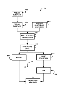
[0029] Figure 5 is a flow chart which illustrates methods for making membranes
according to some embodiments.
[0030] Figure 6 is a graph illustrating the relationship of water vapor
transport to coating
weight for an example embodiment.
[0031] Figure 7 is a graph illustrating the relationship of water vapor
permeability in the
film layer of a membrane to temperature for PEO-PU coated on a silica-loaded
polyethylene substrate and coated on a PP substrate, the latter with and
without
rehydration.
[0032] Figure 8 is a graph showing water vapor transport flux in the membrane
as a
function of temperature for various example embodiments and a control sample
on a
silica-loaded polyethylene substrate.
[0033] Figure 9 is a curve showing results of differential scanning
calorimetry for a
sample polymer according to an example embodiment.
8
CA 02986417 2017-11-17
WO 2016/191868
PCT/CA2016/050610
[0034] Figure 10 is a curve showing the decrease in weight of a sample
membrane
according to an example embodiment as a function of temperature.
[0035] Figure 11 is a set of curves showing results of repeated thermal cycles
for a sample
membrane according to an example embodiment.
[0036] Figure 12 is a set of curves showing results of repeated thermal cycles
for a sample
membrane according to an example embodiment.
[0037] Figure 13 is a set of curves showing results of Fourier transform
infrared
spectroscopy for a sample membrane according to an example embodiment as-cast
and
after exposure to liquid water.
Detailed Description
[0038] Throughout the following description, specific details are set forth in
order to
provide a more thorough understanding of the invention. However, the invention
may be
practiced without these particulars. In other instances, well known elements
have not been
shown or described in detail to avoid unnecessarily obscuring the invention.
Accordingly,
the specification and drawings are to be regarded in an illustrative, rather
than a restrictive
sense.
List of Definitions
[0039] AA ¨ acetic acid
[0040] Barrer ¨ gas permeability unit (1 Barrer = 1 x 10⁻¹⁰ cm3 (STP) cm cm-2s-
1 cmHg-1)
[0041] DCM ¨ dichloromethane.
[0042] DMPA - dimethylpropanoic acid.
[0043] DSC ¨ Differential Scanning Calorimetry, an analytical technique in
which the
difference in the amount of heat required to increase the temperature of a
sample and a
reference material is measured as a function of temperature. Both the sample
and reference
are maintained at nearly the same temperature during the test.
9
CA 02986417 2017-11-17
WO 2016/191868
PCT/CA2016/050610
[0044] ERV ¨ Energy Recovery Ventilation. ERV is used to provide air exchange
in
buildings. ERV transfers both heat and moisture from outgoing air to incoming
fresh air.
ERV is performed using air-to-air heat exchangers that transfer both sensible
heat and
latent heat.
[0045] FTIR ¨ Fourier Transform Infrared Spectroscopy.
[0046] GPU ¨ gas permeance unit (1 GPU = 1 x 10⁻⁶ cin3 (STP) cm251 cinHg-1)
[0047] HMDI - hexamethylene diisocyanate.
[0048] IPDI - isophorone diisocyanate. IPDI may be reacted with polyol to form
isocyanate prepolymers.
[0049] IPA ¨ isopropyl alcohol.
[0050] MDI - diphenylmethane diisocyanate.
[0051] PBT ¨ polybutylene terephthalate.
[0052] PCL ¨ polycaprolactone.
[0053] PEO ¨ polyethylene oxide. Polyethylene oxide is a synthetic polyether
that can
have a wide range of molecular weights. PEO typically has molecular weight of
100,000
g/mol or more. PEOs are amphiphilic and soluble in water as well as in many
organic
solvents (e.g., methylene chloride, ethanol, toluene. acetone, and
chloroform).
[0054] PP ¨ polypropylene.
[0055] PPG - polypropylene glycol.
[0056] PTFE ¨ polytetrafluoroethylene.
[0057] PTMG - polytetramethylene glycol.
[0058] PU ¨ polyurethane
[0059] PD ¨ polymer dispersion. An aqueous system containing dispersed polymer
particles. Aqueous dispersions are attractive for polymer coatings and
membrane
CA 02986417 2017-11-17
WO 2016/191868
PCT/CA2016/050610
fabrication compared to solvent-based systems which have significant
environmental,
economic, and health implications associated with evaporating and exhausting
solvents
during the drying process.
[0060] PI TD ¨ polyurethane dispersion. Polyurethane dispersions (PUT)) are a
subgroup of
Plls in which the polymer particles comprise particles of one or more TPUs.
[0061] RH ¨ Relative Humidity.
[0062] Selectivity - The relative permeance or permeability of two chemical
species
through a membrane, where the higher permeability species is in the numerator.
Selectivity for water vapor transport membranes is usually determined by
measuring the
water vapor permeance and the permeance of another gas that it would be
desirable to
separate water vapor from. For example, water vapor over oxygen selectivity,
or water
vapor over carbon dioxide selectivity. For example, a membrane with 10000 GPU
water
vapor permeance and 100 GPU carbon dioxide penneance has a selectivity for
water vapor
over carbon dioxide of 100.
[0063] TGA - Thermogravimetric Analysis. TGA measures changes in physical and
chemical properties of materials as a function of increasing temperature
and/or time.
[0064] TPU - Thermoplastic Polyurethanes. A family of polymers, which are
highly
customizable to offer a wide variety of end properties. TPUs are widely used
in
applications where toughness, durability, and broad temperature flexibility
are required.
[0065] TDI ¨ toluene diisocyanate.
[0066] WVT ¨ Water Vapor Transport.
Membrane Structure
[0067] Figure 1 shows a membrane 10 according to an example embodiment.
Membrane
comprises a porous substrate 12 and an active layer 14 on a surface 13 of
substrate 12.
Active layer 14 is permeable to water vapor. For ERV applications active layer
10 is much
more permeable to water vapor than it is to other materials (e.g. organic
materials, gases).
11
CA 02986417 2017-11-17
WO 2016/191868
PCT/CA2016/050610
[0068] In some embodiments, active layer 14 is coated on surface 13 of
substrate 12 and
an additional active layer is supported on a second surface of substrate 12
opposed to
surface 13. If it is desired to protect from solvents, for example water, then
active layer 14
may be sandwiched between two substrates 12. Where substrate 12 is porous and
hydrophobic, water would be prevented or inhibited from reaching active layer
14
sandwiched therebetween.
Substrate
[0069] Advantageously, substrate 12 has a high porosity (e.g. a porosity of at
least 30%)
and/or is thin (e.g. has a thickness of less than 150 microns) and/or is
hydrophobic. In
some embodiments, the substrate has all of these features. Substrates of
particular
embodiments have a thickness that is <150 microns, preferably <50 micron, more
preferably <35 microns and a porosity >25%, preferably > 40%. In some
embodiments,
the pores of the substrate are significantly longer in a length dimension than
they are wide.
In some embodiments, an average pore area of individual pores in the substrate
12 is at
least 15000 nm2. In some embodiments, the pores of substrate 12 are smaller
than 150 nm
in at least one dimension.
[0070] Suitable substrates may be made from a microporous polymer, such as
polyolefin
or PTFE-based materials. In some embodiments, the substrate comprises a dry-
stretched
PP battery separator. Such separators are used, for example, in some lithium
ion batteries.
Such separators are commercially available and are reasonably inexpensive in
commercial
volumes.
[0071] In some embodiments, substrate 12 has the property that it does not
inhibit
crystallization of side chains of a polymer material of active layer 14. For
example,
surface 13 of substrate 12 may be substantially free of materials that tend to
inhibit
crystallization of side chains in active layer 14. In some embodiments, the
side chains
comprise PEO and surface 13 of the substrate is substantially free of
materials that tend to
inhibit crystallization of PEO. In some cases surface 13 of substrate 12 is
substantially free
of silica (SiO2) and titanium oxide (TiO2).
12
CA 02986417 2017-11-17
WO 2016/191868
PCT/CA2016/050610
[0072] As described elsewhere herein, active layer 14 may comprise a polymer
which
includes PEO in its main chain and/or side chains. The presence in substrate
12 of SiO2 or
TiO2 tends to inhibit crystallization of PEO groups in active layer 14.
Without being
bound by any particular theory of operation, this inhibitory effect appears to
be associated
with an interaction of PEO groups in the polymer with the SiO2 and/or TiO2 in
the
substrate. This is surprising since one would not expect silica or titanium
oxide to interact
with PEO in this manner. However silica-containing substrates can hold water
molecules.
Water from air or from aqueous coating processes may be retained on the
substrate by the
SiO2 and/or TiO2. This may lead to enough liquid water remaining at the
substrate-
polymer interface after drying of surface 13 to inhibit crystallization of the
PEO.
[0073] In some embodiments, surface 13 of substrate 12 has the characteristic
that it is not
wetted by the material of active layer 14. For example, where active layer 14
comprises a
polymer having PEO side chains, surface 13 may have the characteristic that it
is not
wetted by PEO.
[0074] In some embodiments, surface 13 of substrate 12 has a contact angle
with water of
less than 102 degrees and/or an average roughness Ra of less than 0.8 gm.
[0075] Substrate 12 is preferably inherently flame retardant (made of one or
more flame
retardant materials) and/or tends to shrink away from high-temperature sources
such as
open flames. These properties help membrane 10 to pass flammability testing
(e.g.
according to UL-94, UL-723).
[0076] Substrate 12 may have any combination of the above characteristics.
Active Layer
[0077] Active layer 14 comprises a polymer that can crystallize within a
temperature
range near to that at which membrane 10 will be used. For example, a membrane
10 used
in FRY applications may have a specified working temperature range of 0 C to
40 C and
the polymer may crystallize within 15 C of this range (i.e. in the range of -
15 C to 55 C in
this example).
13
CA 02986417 2017-11-17
WO 2016/191868
PCT/CA2016/050610
[0078] In some embodiments, the polymer is a PEO-based copolymer, in which the
PEO
is responsible for polymer crystallization. The main chain and/or side chains
of such
polymers comprise PEO. PEO side-chain groups are less constrained and are more
available to crystallize than groups present in the polymer main chain. In
some
embodiments, the PEO side chains have molecular weights in the range of 200 to
10000
Daltons. Other crystallizing polymer main chain and/or side chains are
possible. Some
examples are PCL and PTMG. Active layer 14 may, for example, comprise a
copolymer
which comprises ethylene oxide groups in which a significant number of the
ethylene
oxide groups are available for crystallization.
[0079] In some embodiments, the polymer comprises a plurality of different
main chains
and/or side chains. For example, the polymer may comprise a plurality of
different main
chains and/or side chains, each main chain and/or side chain type having a
different
molecular weight leading to a different melting temperature. For an ERV
application the
side chains may be chosen so that all of the side chains (or at least all of a
group of side
chains responsible for varying WVT properties in a temperature range of
interest) may be
in a melted state at temperatures above some threshold temperature (e.g. > 25
C) (i.e. all
of these side chains may have melting temperatures below the threshold
temperature).
[0080] As the temperature falls below this high-temperature threshold,
different groups of
the side chains may crystallize at successively lower temperatures. A membrane
that
incorporates an active layer with this property may provide very high water
vapor
permeability above the high-temperature threshold at which all of the side
chains are in a
melted state. At temperatures below a low temperature threshold all or most of
the side
chains may be crystallized. At such low temperatures, water-vapor transport
through the
membrane may be significantly reduced. At temperatures intermediate between
the low-
temperature threshold and the high-temperature threshold, some of the side
chains may be
in a crystalline form and some of the side chains may be in an amorphous form.
In this
intermediate temperature range the water vapor permeability of the membrane
may have
an intermediate value that changes with temperature.
[0081] By appropriately selecting side chains for the polymer of the active
layer one may
alter the functional relationship between water vapor permeability and
temperature, for
example, by making the transition between a low-permeability state and a
relatively high-
14
CA 02986417 2017-11-17
WO 2016/191868
PCT/CA2016/050610
permeability state more gradual (e.g. by providing a wider range of side-chain
weights) or
more sharp (e.g. by making the side chains more homogeneous).
[0082] In some embodiments, the water vapor permeability of the membrane is
affected
by both temperature and humidity. In such embodiments, for the same
temperature. higher
humidity may cause water vapor permeability to be increased and lower humidity
may
cause water vapor permeability to be decreased. With such a membrane, if high
humidity
occurs at a lower temperature then the membrane can adjust to that by
increasing its
permeability to water vapor. A possible mechanism for such variations in WVT
with
humidity. which is observed in some polymers, is that at high humidity levels
the polymer
may partially wet, thereby disrupting crystallinity. Another possible
mechanism is that
water-vapor-absorptive additives in the coating may modify water uptake in the
film layer
at a relative humidity threshold thereby altering permeability and/or
crystallinity of the
polymer film layer.
[0083] In some embodiments, the polymer comprises blocks that are relatively
long (e.g.
have molecular weights of at least 1000 Daltons). In some embodiments, the
polymer
comprises 40% to 80% soft blocks by weight. In some embodiments, the polymer
comprises 10% to 50% side chains by weight. In some embodiments, the side
chains are
relatively long (e.g. have molecular weights of at least 1000 Da). A polymer
that has
longer soft blocks in its main chain and/or longer side chains will have a
greater
propensity to crystallize as such polymers allow more movement and mobility
generally
facilitates crystallization. Thus, the melting temperature of the polymer may
be altered by
changing the length (and molecular weight) of the main chains and/or side
chains.
[0084] In some embodiments, the polymer side chains include side chains having
a
melting temperature in the range of -15 to 50 C. In some embodiments, at least
50% of the
polymer side chains have a melting temperature within this range.
[0085] The main chain of the polymer of active layer 14 may be cross-linked.
The degree
of cross-linking may be varied. In some embodiments, the main chain is cross-
linked in
the range of 0% to 16% total cross-linker by weight, preferably in the range
of 5% to 12%
total cross-linker by weight. Cross-linking may improve chemical stability and
decrease
solubility and swelling of the polymer in water.
CA 02986417 2017-11-17
WO 2016/191868
PCT/CA2016/050610
[0086] One would normally wish to avoid polymers that tend to crystallize at
or near the
temperature range at which a membrane 10 will be used for ERV or other WVT
applications. This is at least because the WVT across a crystallized polymer
is
significantly impaired in comparison to the WVT across the same polymer in a
non-
crystallized state.
[0087] In some embodiments, the polymer comprises a TPU. TPUs are widely
commercially available and are highly customizable to offer a wide variety of
end
properties. TPUs may, for example comprise polyols and di-isocynates (e.g.
TDI, MDI,
HMDI, IPDI and others) that contain the urethane linkage, -RNHCOOK-. Other
polymers
or co-polymers could provide the polymer main chain in the alternative.
[0088] The general reaction for production of TPUs involves reacting a di- or
polyisocyanate with one or more polyols, such as short chain diols ('chain
extenders')
and/or long chain polyols (typically diols). The resulting block copolymers
contain 'hard
blocks' (or 'hard segments') containing isocyanate groups connected by the
short chain
diols, and 'soft blocks' (or 'soft segments') containing the long chain
polyols (see Figure
2).
[0089] In some currently-preferred embodiments the polyols comprise glycols.
Examples
of glycols are that may be used are PEG and/or PEO which generally have the
structure:
HO-[-CH2-CH2-0-]n-OH, as well as PPG, polypropylene glycol.
[0090] Figure 3 illustrates a general example chemical reaction for forming
TPUs and
shows the general structure of an example TPU. Figure 4 illustrates an example
chemical
reaction for forming a PEO-PU copolymer having main chain and side chain PEO
segments may be formed. The reaction of an isocyanate with an alcohol group
produces an
ethyl carbamate or "urethane" linkage, and through a step growth addition
polymerization
process linear block copolymers are created. TPUs may be constructed using any
of a
broad range of monomeric building blocks (i.e. isocyanates and polyols) which
can be
incorporated in the final polymer to tailor the polyurethane functionality and
properties.
TPUs are often classified by the monomeric building blocks (e.g. isocyanates
and polyols)
used in their fabrication. Categorizations include aliphatic or aromatic
diisocyanates and
polyether or polyester diols.
16
CA 02986417 2017-11-17
WO 2016/191868
PCT/CA2016/050610
[0091] In some embodiments, the polymer used is an aliphatic diisocyanate-
polyether
polymer. In some embodiments, the TPU main chain includes longer chain diols
that
provide secondary crystalline/amorphous regions in active layer 14. Such
longer chain
diols may make up, for example, 10% to 60% of the total polymer weight.
[0092] Polyurethane dispersions (PUD) are a subgroup of TPUs in which polymer
particles are dispersed in an aqueous system. Aqueous dispersions are
attractive for
polymer coatings and membrane fabrication compared to solvent-based systems
which
have significant environmental, economic, and health implications associated
with
evaporating and exhausting solvents during the drying process. In formulating
PUD,
diisocyanate and diols are initially reacted to create a pre-polymer' which is
then mixed
in water in a secondary step where it is reacted with a 'chain extender' e.g.
a short-chain
diol to increase the polymer molecular weight. A dispersion of polymer
particles in water
remains at the end of the reaction.
[0093] Since the polymer in a PUD is in a water dispersion it may benefit from
cross-
linking once cast in order to improve chemical stability and decrease
solubility in water.
Polyurethanes often incorporate a number of active functional groups on which
the cross-
linking reaction can be based. These can include amine, hydroxyl, and/or
carboxyl groups
in the polyurethane. Cross-linking may be promoted by adding a cross-linker
which reacts
with these active functional groups. The degree of cross-linking may be
controlled by
varying the amount of cross-linker provided. Cross-linker may be added to the
PUD
before the PUD is applied to the substrate. Cross-linking occurs as the active
layer dries on
the substrate.
[0094] Suitable cross-linkers for polyurethanes include isocyanates, which
will react with
hydroxyl and amide functional groups, and carbodiimides and aziridines which
will react
with carboxyl functional groups. Some embodiments use aqueous polycarbodiimide
dispersions as cross-linkers. Such dispersions are available for cross-linking
aqueous
polyurethane dispersions under room temperature conditions with good pot life.
Cross-
linking leads to a large increase in the polyurethane molecular weight,
rendering the
coating insoluble in place.
17
WO 2016/191868
PCT/CA2016/050610
[0095] Carbodiimide cross-linking may be applied to cross-link carboxylic acid
containing
polyurethanes. A particularly appropriate cross-linker for aqueous
polyurethane systems is
an aqueous dispersion of polycarbodiimide from StahlTM, picassianTM XL702.
Carbodiimide groups in the cross-linker react with a carboxyl group in the
urethane
leading to an N-acyl urea bond. Acidic conditions are necessary as the
carboxyl group
must be protonated for the reaction to proceed. This is beneficial as the pot
life will
generally be extended in relatively neutral aqueous dispersions. After
coating, during the
drying process, the reaction will proceed as water evaporates from the
dispersion and the
carboxyl groups become most acidic and protonated. The manufacturer describes
the
reaction associated with polycarbodiimide as occurring on polymer drying as
the pH drops
and carboxyl groups in the TPU become activated. This reaction will greatly
increase the
molecular weight of the polymer, and the swell in water and solubility of the
polymer in
water should decrease.
[0096] In some embodiments, the active layer is formed from, PERMAXTm 230
polyurethane dispersion available from Lubrizol Advanced Materials. PERMAXTm
230 is
an "aliphatic polyether waterborne polyurethane dispersion". The development
and
properties of PERMAXTm polymers are described in A. V. Lubnin, "Novel,
'Breathable'
Polyurethane Dispersions," Paint & Coatings Industry Magazine, 2005 and in I1S
patent
6897281.
[0097] The polyurethane polymer may contain between 12 and 80% by weight
poly(alkylene oxide) side chains. The side chain monomer may, for example be
incorporated into the polyurethane main chain from the polyol TegomerTm D-
3404, a
polyether-1,3-diol available from Evonik with an average molecular weight of
1200 g/mol.
Such side chain units allow the incorporation of a large amount of hydrophilic
PEO into
the polymer while still allowing workable aqueous dispersions to be made. In
such
embodiments the main chain unit also contains poly(alkylene oxide) in amounts
less than
25% of the total weight which are incorporated through the use of a polyether
polyol.
[0098] Making the PERMAXTm polymer involves reacting a diisocyanate or
polyisocyanate, for example, IPDI, MDI, TDI) with a poly(alkylene oxide) side-
chain diol
and a poly(alkylene oxide) main chain diol in the presence of heat and a
catalyst to
generate a isocyanate terminated pre-polymer. Some preferred embodiments of
the
18
Date Recue/Date Received 2021-06-29
CA 02986417 2017-11-17
WO 2016/191868
PCT/CA2016/050610
PERMAXTm polymers contain at least one compound which incorporates a cross-
linkable
functional group into the polymer. For example, DMPA may be used to add
carboxyl
functional groups to the polyurethane. The pre-polymer is then dispersed in
water and
reacted with a chain extender (e.g. hydrazine) to create the final
polyurethane dispersion.
[0099] In some embodiments, the polymer contains PEO side chains which make up
approximately >30% of the total weight of the polymer and total soft segments
which
make up approximately 65% of the total weight of the polymer. Such polymers
may have
¨1.7 to 2 parts diisocyanate hard groups to soft groups on a molar basis. One
example of
such a polymer is PERMAXTm 230. In some embodiments no main chain PEO is
present.
In other embodiments PEO is present in the main chain of the polymer. In some
such
embodiments, the ratio of side chain to main chain PEO is approximately 0.75
to 1.5 on a
molar basis.
[0100] In addition or as an alternative, active layer 14 may comprise other
block
copolymers with PEO soft segments. Examples of such block copolymers include:
polyether block amides such as PEBAXTM, PEO-PBT, Polyether-polyamides,
polyether-
polyurethanes, and other PEO-PU.
Method of Manufacture
[0101] Figure 5 illustrates a method 20 for making a membrane. In block 21 a
suitable
substrate is provided. The substrate may, for example, be as described above.
In some
embodiments, the substrate is a dry stretched or wet processed
polypropylene/polyethylene
substrate. In optional block 22 the substrate is prepared to receive the
active layer 14.
Block 22 may, for example, comprise corona treatment of the substrate.
[0102] In block 23 a solution or dispersion is prepared for use in forming the
active layer.
The solution or dispersion contains the polymer and optionally contains other
additives.
Additives that may be included in the solution or dispersion include:
surfactants (e.g. a
non-ionic surfactant such as TritonTM X-100), lithium chloride,
antimicrobials, sorption
additives, inorganic additives such as silica, titanium, and alumina, and/or
plasticizers such
as PEG 200.
19
CA 02986417 2017-11-17
WO 2016/191868
PCT/CA2016/050610
[0103] Aqueous dispersions are preferred in order to avoid the use of solvents
that have
negative environmental impacts and/or require special handling. In example
embodiments
the solids content of the solution or dispersion is in the range of 20 to 40%
solids by
weight. Using solutions or dispersions with lower solids content allows for
thinner film
layers. However, such solutions or dispersions have higher water content which
makes
wetting the substrate and forming a continuous film (active layer) on the
substrate more
challenging.
[0104] The polymer is preferably cross-linked. Cross-linking of the polymer
may occur
primarily between 'cross-linking groups' in or near urethane 'hard blocks'.
The cross-
linking groups are preferably carboxyl groups. Cross-linking of the polymer
increase the
chemical stability of the polymer and helps to make the active layer less
soluble in water
after application.
[0105] In block 24 the solution or dispersion prepared in block 23 is applied
to the
substrate to create the active layer. Without being limited to a specific
method, application
may, for example comprise gravure coating, meter rod coating, roll coating,
slot die
coating and spray coating. Slot die coating is preferred to provide thin
uniform coatings on
the substrate surface.
[0106] In block 25 the active layer is dried and cured. After curing, a
continuous dense
film layer of polymer covers the substrate surface. The dense layer is
substantially free of
'micro' pores. In some embodiments, the thickness of the active layer is in
the range of 0.5
to 10 microns (for example, a coating weight of ¨0.5 to 10 g/m2).
[0107] Curing may be performed by drying the active layer. This may be done in
air. In
some embodiments, curing comprises drying the coated substrate in air at a
temperature of
20 C to 90 C for a period of 2 hours or more. Drying may be expedited by
heating the
active layer. For example, in other embodiments drying occurs in a roll to
roll process in a
heated convection oven and under IR heating. In such embodiments, drying of
the active
layer may be completed in a time on the order of 30 seconds or even less.
[0108] Blocks 26 and 27 provide post-curing steps to modify the
characteristics of the
active layer. In some embodiments, neither of blocks 26 and 27 is performed
(as indicated
CA 02986417 2017-11-17
WO 2016/191868
PCT/CA2016/050610
by arrow 29). In some embodiments, block 26 is performed. In some embodiments.
block
27 is performed. In some embodiments, both of blocks 26 and 27 are performed.
[0109] Block 26 is an annealing step in which the coated substrate is held at
an elevated
temperature (e.g. a temperature in excess of a transition temperature of the
polymer in the
active layer) for a period of time and then cooled at a specific rate. Block
26 may have the
effect of depressing the transition temperature.
[0110] Block 27 is a transition-inhibiting step which involves incorporating
molecules of a
polar solvent into the active layer. Block 27 may comprise, for example
contacting the
active layer with a liquid polar solvent for sufficient time to allow
molecules of the polar
solvent to enter the active layer and bind to the polymer side chains. The
solvent is
preferably a protic polar solvent such as water, isopropyl alcohol, methanol
or ethanol.
[0111] Non-protic polar solvents such as acetone may be used in block 27 in
cases where
it is desired to not completely eliminate a transition in the polymer. IR
studies of a
membrane soaked in acetone after curing show that some crystallization was
still present
in the PEO groups in the coating after the acetone soak.
[0112] In some embodiments, block 27 comprises contacting the active layer
with liquid
water. This may be performed at room temperature or above. Contacting with
liquid water
may comprise, for example, spraying, misting or dipping. At room temperature
even a
very short period of contact (e.g. 1 second) can be sufficient for enough
water to be taken
up to substantially eliminate crystallization of PEO in the active layer.
[0113] Without being bound to any particular theory of operation, it is
believed that an
effect of block 27 is that PEO segments of the polymer become attached to
molecules of
the solvent by hydrogen bonds. The solvent (e.g. water) becomes 'bound' in
place rather
than being in the form of liquid water.
[0114] After block 27, water may be present in three states in the polymer:
bound, bound-
freezing, and freezing. Bound water binds directly to segments in the polymer
(e.g. PEO
segments in the polymer) via hydrogen bonding. Bound water in the polymer will
not
freeze at any temperature. Bound-freezing water is associated directly with
the bound
water in the polymer via hydrogen bonding within the hydration shell of the
polymer.
21
CA 02986417 2017-11-17
WO 2016/191868
PCT/CA2016/050610
Bound-freezing water is not directly bound to the polymer itself. Bound-
freezing water
freezes at temperatures below the normal freezing point of water. Freezing
water is free
(i.e. not bound to the polymer). Freezing water freezes at the normal freezing
point of
water.
[0115] Only a fraction of the PEO segments in the polymer needs to be bound by
bound
water to prevent crystallization of active layer 14. The theoretical maximum
amount of
bound water is 2 molecules of water per ethylene-oxide monomer in the polymer.
For a
polymer that is 70% by weight PEO segments, 2 molecules of water per ethylene-
oxide
monomer corresponds to the bound water having a weight equal to about 40% of
the
polymer weight. Generally, significantly less than 2 molecules of water per
ethylene oxide
monomer in the polymer can suffice to prevent crystallization of the PEO
segments. It has
been found that a very small uptake of water into the active layer can suffice
to prevent
crystallization of PEO groups in the active layer. Bound water associated with
a small
fraction of ethylene oxide groups can disrupt crystallinity and prevent
further
crystallization.
[0116] In some embodiments, block 27 results in an increase in the mass of the
active
layer in the range of 3% to 100% (i.e. the amount of solvent that becomes
bound to the
polymer in the active layer in block 27 is in the range of 3% to 100% of the
weight of the
polymer). Where the solvent is water a preferred range is 3% to 30% of the
polymer
weight, more preferably 3% to 10% of the polymer weight. Excessive water take
up can
cause swelling of the active layer.
[0117] The amount of water taken up by the active layer can be controlled by
adjusting the
time that the active layer is contacted with liquid water as well as the
drying time during
which excess water is removed. For example, in a roll-to-roll process the line
speed, the
application method, and the drying conditions will influence the amount of
water
incorporated into the membrane. A desired amount of water uptake can typically
be
achieved in 1 to 30 seconds of exposure to liquid water.
[0118] Spectroscopic methods such as FTIR may be used to evaluate whether a
membrane
has been treated as described herein. Presence of water in the membrane causes
a shift at a
wavenumber of ¨1100 cm-1 in the IR. This shift is associated with -C-O-C-
bonds in the
22
CA 02986417 2017-11-17
WO 2016/191868
PCT/CA2016/050610
PEO groups. Also, for membranes that have not been subjected to block 27, PEO-
CH2-
results in clear peaks at 1344 cm-land 1359 cm-lwhich are associated with the -
CH2- in
crystallized PEO. These peaks are absent or at least much less pronounced
after block 27
treatment. Membranes which are subject to complete treatment have a broad peak
at 1349
cm associated with the ¨CH2¨ in amorphous PEO.
[0119] In block 28 the membrane is dried. Drying may comprise, for example,
drying in
air until substantially all excess surface water is removed. In some
embodiments, block 28
is performed at a temperature that is elevated relative to room temperature
(e.g. a
temperature in the range of 25 C to 80 C).
[0120] In a method according to an example embodiment, a membrane 10 is
prepared by
applying an active layer comprising a co-polymer comprising PEO side chains to
a
stretched PP substrate 12. The application may be performed by applying an
aqueous
dispersion comprising the polymer and a cross-linker to the substrate. The
active layer is
allowed to cure until the active layer covers a surface of the substrate
continuously and is
mostly free of water. After curing the active layer is subjected to a
rehydration step that
involves contacting the active layer with a liquid polar solvent, for example
water.
Preferably during this rehydration step the solvent is water and the active
layer is allowed
to take up water in an amount equal to 3% to 30% of the polymer weight, more
preferably
3% to 10% of the polymer weight.
[0121] On a molecular basis, water take-up in the amount of 3% to 30% of the
polymer
weight corresponds to about 0.1 to 1.1 bound water molecules per ethylene
oxide group in
the polymer. Water take-up in the amount of 3% to 10% of the polymer weight
corresponds to about 0.1 to 0.4 bound water molecules per ethylene oxide
group. Water
take-up within these ranges is typically sufficient to prevent crystallization
of the PEO
segments of the polymer and prevent active layer crystallization.
Switching
[0122] By appropriate selection of a polymer and substrate one can create a
membrane in
which the WVT can be switched between a state in which the membrane provides a
relatively high permeability to water vapor and a state in which the membrane
provides a
23
CA 02986417 2017-11-17
WO 2016/191868
PCT/CA2016/050610
much lower permeability to water vapor. Switching between these two states may
be
temperature controlled. In some embodiments, the water vapor permeability of
the two
states differs by a factor of at least 3, or at least 7 in some embodiments.
[0123] Such switching may be applied, for example, to provide an ERV core with
a
membrane that provides high permeability to water vapor at higher temperatures
(e.g.
>25 C). and lower permeability to water vapor at lower temperatures (e.g. <25
C). Such
an ERV core may perform better than a heat recovery ventilation (HRV) (i.e.
thermal
transfer only) core by returning some (but not too much) moisture to the
indoor space in
heating conditions. Allowing some moisture transport at sub-zero outdoor
conditions
allows the ERV core to operate at lower temperatures without requiring
defrosting. This
improves the overall efficiency of the system.
[0124] Table 1 illustrates desirable water vapor permeability for ERV cores as
a function
of temperature:
Table 1 - AHRI 1060 Standard Conditions
Outdoor Condition Indoor Condition
North
HVAC Moisture
American T RH gH20/ T RH gH20/
Operation Permeability
Season ( C) (%) kg air ( C) (%) kg air
Required
Cooling
Summer 35 47 16.7 23.9 52 9.6 HIGH
Condition
Heating MODERATE
Winter 1.7 82 3.5 21.1 48 7.5
Condition to LOW
Extreme -20 100 0.6 21.1 48 7.5 MODERATE
[0125] In order to achieve a 'switching effect' the polymers preferably
include
components (e.g. side chains) that have a melting point or other transition
within the range
of interest for the switch. In some embodiments, such components are present
in
microdomains within the active layer. The structure of the components within
the
microdomains may change from crystalline to amorphous depending on the
temperature.
[0126] A polymer with a significant proportion of side chains (e.g. >20% of
the side
chains) in which the side chain polymer has a melting point of 45 C, will have
a switch
temperature at ¨45 C when the side chain polymer is incorporated into the co-
polymer.
However since the co-polymer contains hard segments which are higher melting
(e.g.
24
CA 02986417 2017-11-17
WO 2016/191868
PCT/CA2016/050610
>180 C) and/or have cross-linking, the co-polymer will still be a solid even
after the side
chain 'soft segments' melt such that membrane 10 can retain its structural
integrity even at
temperatures above the melting point of the side chains.
[0127] This switching behavior was initially observed as a very significant
decrease in
water-vapor permeability of membranes that occurred within a few hours or a
day after
making the membranes by deposition of an active polymer layer on a PP
substrate. It was
found that heating the membranes to a threshold temperature caused water-vapor
permeability of the membranes to greatly increase. The water-vapor
permeability of the
membranes returned to the relatively low value when the membranes were cooled
back to
room temperature.
[0128] When TPU coatings were applied to PP substrates, immediately after
coating the
resulting membranes had reasonably high water-vapor permeability at both 25 C
and
50 C. After that there was a rapid decrease in water vapor permeability at 25
C. This
decrease did not occur when the identical polymer was applied to silica-loaded
polyethylene substrates.
[0129] The decrease in water-vapor permeability at 25 C generally occurred
rapidly - in
less than 24h (as little as 3h after coating), but crystallization times will
depend on the
specific polymers and the ambient conditions. Water vapor permeability
measured
isothermally at 50 C remained normal. Table 2 shows results of experiments
which
demonstrate this effect. The 'Day l' column reports water-vapor permeability
measured
within a few hours of coating and drying the polymer. The 'Day 2' column
reports water-
vapor permeability measured approximately 24 hours later. The samples were dry
stretch
polypropylene battery separators (PP) coated with PERMAXTm 230 (PU) at four
levels of
StahlTM XL-702 polycarbodiimide cross-linker (XL). The samples are reported in
thickness normalized and vapor pressure differential normalized flux
(permeability) for
the film layer only in Barrer units (1x10-11) cm3 (STP) cm cm-2 s-1 cmHg-1),
but all
membranes had coatings in the range of 0.8 to 1.4 g/m2 and samples were coated
and dried
at room temperature.
Table 2¨ Water vapor permeability of membranes
Membrane % Cross- Day 1 Day 2
CA 02986417 2017-11-17
WO 2016/191868
PCT/CA2016/050610
linker
Permeability Permeability
Permeability 25 C
25 C 50 C
(Barrer*)
(Barrer) (Barrer)
PP-PI T-0%XL 0 47752 5332 39819
PP-PU-3%XL 3 37659 3658 43574
PP-PU-6%XL 6 36772 4210 38002
PP-PU-12%XL 12 26470 4443 28426
*Film layer permeability in Barrer units is flux normalized for film layer
thickness and
vapor pressure differential. Substrate and boundary layer water vapor
transport resistances
are subtracted from the observed resistance to determine the water vapor
transport
resistance of the film layer. Feed stream humidity was 50% relative humidity
at the stated
temperature; sweep stream was 0%RH at the stated temperature.
[0130] At temperatures of 50 C and above the membranes performed as expected
for all
thicknesses. Water vapor flux at 50 C (not normalized for thickness) decreases
linearly
with increasing thickness or coating weight (see Figure 6). The water vapor
permeability
of the membranes was significantly lower than expected at temperatures below
50 C (see
Figure 7), where the membrane based on a PP substrate shows significant
temperature
dependence on water vapor permeability. This effect was not observed when
samples were
coated on silica-polyethylene substrates where permeability to water vapor is
essentially
the same at all temperatures. Figure 7 shows the temperature dependence of the
water
vapor permeability of membranes made by casting a cross-linked PEO-PU polymer
on
two substrates. One substrate (PP substrate) is a dry stretch polypropylene.
The other
substrate (5i02-PE) is a silica-loaded polyethylene substrate. The effect of
adding water to
the PP substrate coated with PEO-PU is shown as well.
[0131] It is believed the temperature-controlled permeability of the membranes
made with
the PP substrate is associated with crystallization and melting of soft
segments in the co-
polymer (further discussed herein). This would lead to a decrease in polymer
mobility and
thus a decrease in water vapor diffusion through the polymer. As the
temperature increases
the portion of the polymer that is crystallized melts, leading to an increase
in polymer
mobility and an increase in permeability at higher temperatures.
26
CA 02986417 2017-11-17
WO 2016/191868
PCT/CA2016/050610
Switching ¨ control of switching temperature
[0132] The temperature at which the WVT properties of a membrane as described
herein
change can be controlled by selection of the polymer used for active layer 14
and also by
treatments applied to the membrane. The switching effect is more pronounced
for thicker
active layers 14.
Temperature Control - Annealing
[0133] The transition temperature at which the water vapor permeability of a
membrane
changes can be reduced by performing an annealing step in which the membrane
is
held at an elevated temperature for a period of time and then cooled a
specific rate. The
elevated temperature is preferably at least equal to the transition
temperature.
[0134] Heating and then cooling effects the crystallization of the PEO side
chains. Heating
above 50 C causes the side chain polymer segments to melt, and then
recrystallize on
cooling with a different transition point. Table 3 shows results of
experiments which
demonstrate this effect. The PEO-PU samples were cross-linked with 7% cross-
linker and
dried at room temperature, in the study of the thermal transitions observed in
the materials
the samples were heated to the maximum temperature indicated before cooling at
a rate of
10 C/min to -75 C, before the next heating cycle was measured. Here Tg is the
soft
segment glass transition, while Tx,1 and Tx,2 are believed to be associated
with melting of
PEO crystalline segments in the polymers.
27
CA 02986417 2017-11-17
WO 2016/191868
PCT/CA2016/050610
Table 3 - Transition temperatures at which the water vapor permeability
changes
Thermal Transitions
Max Temp.
Tg,s ( C) Tx,1 Tx,2 AH,2
( C)
( C) (CC) (W/g)
25 -52 27.2 49.5 .08672
55 -52.4 28.1 52.9 0.0424
75 -53.0 28.4 55.0 0.01585
95 -52.6 27.8
115 -52.3 27.5 - -
135 -53.4 27.4 - -
155 -52.0 32.2 - 0.1941
175 -52.0 30.4 - 0.6757
195 -53.3 29.5 - 1.247
[0135] Another way to control the transition temperature is to include
additional materials
such as lithium chloride and/or a surfactant such as TritonTm X-100 in active
layer 14.
Addition of Lithium Chloride
[0136] In these samples, PEO-PU polymer (PERMAXTm 230) films with 7% cross-
linker
and different ratios of lithium chloride were created. Table 4 shows results
of experiments
which demonstrate the effect on WVT as the LiC1 content is increased. With 4%
LiC1,
water vapor permeability at 25 C is maintained. 'The thermal transition
associated with the
PEO crystalline segment melting is modified with increasing LiC1 content in
the
membrane.
Table 4 - Transition temperatures at which the water vapor permeability
changes as
a function of LiC1 content
LiC1 Permeability, 25 C Permeability 50 C
Thermal
Content in (Barrer) (Barrer)
coating Day 1 Day 2 Tg(s) Tx(2nd)
0% LiC1 37774 4424 41145 -52.2 30.4
1% LiC1 35644 9134 47363 -56.8 16.1
2% LiC1 37867 41616 57628 -59.2 12.5
4% LiC1 58903 63258 125367 -
Inhibiting Switching
[0137] Some embodiments apply a process for inhibiting switching such that a
polymer
that would otherwise provide dramatically reduced permeability to water vapor
at lower
temperatures (e.g. temperatures below melting points of most or all of the PEO
side chains
28
CA 02986417 2017-11-17
WO 2016/191868
PCT/CA2016/050610
of the polymer in the active layer) will retain a high permeability to water
vapor (e.g. a
permeability of at least 20000 Barrer) even at such lower temperatures.
[0138] The transition can be substantially eliminated by a process that
involves contacting
membrane 10 with a liquid polar solvent after active layer 14 has cured. The
polar solvent
is water in preferred embodiments.
[0139] It is believed that allowing active layer 14 to take up water (or
another polar protic
solvent) will create a significant number of hydrogen bonds to the PEO groups.
The
presence of such bonds is a possible explanation for the effect on WVT of
contacting the
active layer 14 with water. Such hydrogen bonds may stabilize the polymer
against
crystallization. Suitable solvents include water, methanol, and ethanol. Of
these, solvents
having smaller molecules are preferred. Solvents having larger molecules (e.g.
ethanol,
IPA) will generally have a lower tendency to stay bound in the polymer than
smaller
molecules such as water.
[0140] Acetone may be used in an alternative, although F1'IR studies show that
contact
with acetone does not completely inhibit crystallization of PEO groups in the
samples
tested. The PEO side chains in the tested samples were soluble in acetone.
This explains
why acetone can disrupt crystallization of PEO side chains, but will not
stabilize the side
chains through hydrogen bonding as water is thought to do. It was found that
acetone
vapor also served to disrupt crystallization in the polymer. WVT performance
was
recovered after exposing samples of the membrane to acetone vapor (saturated
at 50 C and
saturated at 25 C).
[0141] Table 5 indicates the results of experiments in which similarly-
prepared samples
each comprising a layer of polymer on a PP substrate were contacted with
different
solvents after curing. Samples were made up of a PP substrate coated with a
PEO-PU
polymer with 7% cross-linker. The samples were dried at room temperature prior
to
testing. For solvent testing, the samples were exposed briefly to the liquid
solvents. It can
be seen from Table 5 that washing with water, ethanol, isopropyl alcohol and
acetone all
yielded samples having permeability to water vapor more than twice the
permeability of
an unwashed control sample. Washing with hexane did not yield this effect.
29
CA 02986417 2017-11-17
WO 2016/191868
PCT/CA2016/050610
Table 5 ¨ Effect of contacting cured membranes with various solvents
Flux at Time (kg/m2/day), 25 C, 50% RH in feed
After Day 3 Day 5 Day 10
Treatment
Control (No
treament) 3.390 3.182 3.459
Water 8.716 8.278 8.826 8.233
Isopropyl Alcohol 8.614 8.659 8.577
Ethanol 8.525 8.609 8.583
Acetone 8.556 7.591 8.023
Hexane 2.426 2.089 2.152
[0142] Samples rehydrated with water were heated to temperatures up to 150 C.
This
heating did not appear to drive out the water that had been taken up by the
active layer in
the rehydration step. The water appears to have been 'bound' in place in the
active layer.
DSC performed during the heating indicated very little endothermic activity
(meaning that
there was no significant evaporation of water from the active layer during the
heating).
[0143] Inhibition of switching was not observed when cured samples were
exposed to
water vapor instead of liquid water. In one test, exposure to water vapor (-
95% RH) at
50 C did not have the effect of improving permeability to water vapor at lower
temperatures.
[0144] Another way to inhibit the transition that causes a reduction in WVT at
lower
temperatures is to add lithium chloride to the active layer. Addition of 4% by
weight of
lithium chloride prevented the reduction in WVT. It is expected that other
hygroscopic
salts would have the same effect; however the addition of these salts effects
may alter
manufacturing and durability of the membrane film layer.
Additional Treatment Steps ¨ Corona Treatment
[0145] In some embodiments, surface 13 of substrate 12 is subjected to corona
treatment
before active layer 14 is applied. Corona treatment may improve the
wettability of surface
13 and thereby promote deposition of an even active layer 14. Corona treatment
involves
using a high voltage electric discharge in which electrons break polymer
surface bonds
creating free-radicals which, in the presence of air, creates various oxygen
containing
functional groups on the substrate surface. The presence of these functional
groups
increases surface energy and improves wetting. Corona treatment may be used to
improve
CA 02986417 2017-11-17
WO 2016/191868
PCT/CA2016/050610
the `wettability' of low surface energy substrates including polyolefins such
as
polypropylene and polyethylene.
[0146] Samples of dry process-microporous polypropylene battery separator
material were
corona treated and then coated with PEO-PI J. Control samples were prepared in
the same
manner but without the corona treatment. The corona-treated samples were
compared
against the control samples and then `rehydrated' and tested to compare
performance of
the corona-treated samples with other samples that were not corona treated.
The
performance of the corona treated samples was generally similar for the
samples after
rehydration, while the untreated samples had very low performance without
hydration,
indicating that the corona treatment of the material worked to prevent
significant
crystallization. Table 6 shows results of experiments which demonstrate this
effect.
Table 6¨ Effect of Corona Treating Membranes
Flux (kg/m2/day), 25 C
After After
Casting rehydration
and
drying
Control Samples 1.7 7.7
Corona 1 6.7 7.3
Corona 2 5.6 7.2
Corona 3 7.0 6.9
[0147] However FTIR scans of the samples demonstrated that there was PEO in
the
crystalline state in the membranes. Also, samples which were tested after some
time
showed that the corona-treated samples decreased in performance indicating
that
crystallization still occurred slowly.
Additional Treatment Steps ¨ Addition of Surfactant
[0148] TritonTm X-100 (CAS #9002-93-1) was added to the PEO-PU polymers prior
to
coating of the PP substrates. The addition of TritonTm X-100 appears to
improve
performance loss at high loadings of Tritonim X-100. However, even with high
loadings
of TritonTm X-100, water vapor permeability was observed to decrease overtime,
the
addition of Tritonrm X-100 did not appear to have any significant effect on
transition
31
CA 02986417 2017-11-17
WO 2016/191868
PCT/CA2016/050610
temperatures. Table 7 shows results of experiments which demonstrate the
effects of
addition of Tritonrm X-100.
Table 7 - Triton rm X-100 addition
WVT 25 C Thermal
% Triton (kg/m2/day)
100X in After Tg(s) Tx, Tx, C
coating Wash C After
Day 1 Days
layer As heating
cast
0% 8.6 2.6 8.5 -53.1 51.0 28.7
Triton TM
X-100
0.5% 8.1 2.9 8.0 -49.2 50.3 36.6
Triton TM
x-100
1% 8.1 2.3 8.1 -49.3 50.3 35.6
Triton TM
x-100
2% 8.2 5.3 8.2 -52.1 48.0 32.8
Tritolirm
X-100
4% 8.1 5.7 8.1 -50.7 49.8 31.3
Triton TM
x-100
[0149] All samples were coated on a dry stretched PP substrate. TritonTim X-
100 was
added in different loadings to the PEO-PU coating solution prior to drying
overnight in
ambient conditions.
[0150] Tritolirm X-100 at 2% and 4% loading (total mass in coating) both
appear to
significantly reduce performance degradation; however water-vapor permeability
at 25 C
still drops significantly over a two week period.
[0151] Washing the samples in water appeared to reverse any performance loss.
This
recovery of water vapor permeability appeared to be permanent. Table 12 shows
results of
experiments which demonstrate this effect. The samples in Table 12 were made
of a dry
stretch PP substrate coated with a formulation of PEO-PI1 with 7% cross-linker
and
different loadings of TritonTm X-100. The samples were then dipped in liquid
water and
then tested.
32
CA 02986417 2017-11-17
WO 2016/191868
PCT/CA2016/050610
Cross-linking
[0152] Increasing the amount of cross-linker decreases absorption of water up
to ¨15%
cross-linker weight by solids. The total liquid water uptake of samples of
PERMAXTm 230
at different levels of XL-702 cross-linker are shown in Table 8. Increasing
the amount of
cross-linker decreases the swelling of the polymer in water, at least up to 9%
cross-linker
by weight. At higher amounts of cross-linker there are less significant
changes in swelling,
indicating that higher levels of cross-linking have less impact on swelling
and water
uptake in this system.
Table 8 ¨
Samples (XL:PU wt.) Wt. % Cross-linker Mass% Water Uptake
at Steady State
0 0 134
1:25 3.85 113
1:20 4.76 108
1:15 6.25 102
1:10 9.09 92
1:5 16.67 87
[0153] DSC studies show that there is little effect on the crystallization of
the soft
segments associated with cross-linking. Since the cross-linking is occurring
on the 'hard'
PU segments of the polymer, there is little impact on the PEO crystallinity.
Rehydration/Wetting
[0154] Switching may be turned off to maintain high performance of the
membranes over
a wider range of temperatures by applying a `rehydration' step. The
rehydration step may
be short (e.g. a 1 second dip in room temperature water). After initially
drying and then
rehydrating the membrane performance returns to the expected level. Table 9
shows
results of experiments which demonstrate this effect.
33
CA 02986417 2017-11-17
WO 2016/191868
PCT/CA2016/050610
Table 9 -
Condition Measured Thermal
weight of Tg(s) Tx, C
water in After
polymer heating
(%)
Room Temp and humidity 2.7 -51.0 28.3
is soak 3.4 -51.5
30s soak 6.4 -51.5
90s soak 12.2 -52.9
150s soak 21.2 -60.8
900s soak 36.8 11.M.
50% wt. water added 43.8 n.m.
75% wt. water added 68.3 n.m.
Saturated in water (72 94.7 n.m.
hours)
n.m. = not measured
[0155] The following samples were coated with a PEO-PU-6%XL coating on dry
stretched PP. After coating, hydrating and drying the samples retain high
membrane
performance. No initial performance reduction was observed for a non-hydrated
sample
kept at 50 C (dry condition) since this temperature is above the PEO melting
point.
However, performance was observed to drop when the sample was left at ambient
conditions. Table 10 shows results of experiments which demonstrate this
effect.
Table 10 -
Samples (PP+PU+XL) WVT 25 C (kg/m2/day)
As 24h
Cast 96h 144h
Coated and kept in 50 C oven for 24h 8.1 7.4 2.8 3.2
Coated, dried, rehydrated @24h before test 7.6 7.8 7.4 7.9
Washed substrate, dry, coated, dried 8.0 2.1 2.7
Coated and dried 8.1 2.3 2.8
[0156] All samples maintained performance after hydration for even a short
period (30
seconds), whether they were kept at 50 C (dry) or ambient temperature and
humidity.
Table 11 shows results of experiments which demonstrate this effect.
34
CA 02986417 2017-11-17
WO 2016/191868 PCT/CA2016/050610
Table 11 -
Data Water Vapor Transport At 25 C (kg/m2/day)
24h after 2.411 2.013 1.656 4.77
coating
treatment 30 sec 25C wash 3 hr 25C wash 3 hr 50C wash 3 hr 25C
wash
48h 8.259 8.944 8.800 8.513
treatment kept at ambient 4 hr 50C 10%RH kept at ambient kept at ambient
52h 8.55
treatment 2 days 50C 10%RH
120h 8.511 8.406 8.699 8.322
treatment 2 days ambient 2 days 50C 10%RH
192h 7.92 8.469
Ambient Ambient
240h 8.636 8.593
264h 8.836
[0157] Samples maintained performance after hydration, provided the time
between
casting and hydrating the sample was at least 24 hours. Table 12 shows results
of
experiments which demonstrate this effect.
Table 12 -
Time Between Casting and Water Vapor Transport at 25 C (kg/m2/day)
Hydration (h) Initial Performance Final Performance
(After 7
Days)
0 6.4 3.0
2 6.5 5.3
18 6.1 5.0
42 6.3 6.4
66 6.4 6.5
90 6.6 6.6
114 6.6 6.6
[0158] Adding water to the samples appears to plasticize the polymer as the
soft segment
Tg is lowered from -51.5 C to -67.7 C. Table 13 shows results of experiments
which
demonstrate this effect. At temperatures between 0 C and 60 C, no PEO melting
was
observed for the hydrated samples.
CA 02986417 2017-11-17
WO 2016/191868 PCT/CA2016/050610
Table 13 -
Sample XL (%) Thickness Hydration Water Tg(s)
(pm) Time (s) Uptake (%) Dry Wet
0 0 576 300 40.5 -51.5 -67.7
1:15 6.7 378 150 36.8 -51.5 -65.7
1:5 16.7 290 150 36.7 -52.5 -64.0
[0159] Increasing cross-linking to a high level may lead to slightly lower
water vapor
transport performance due to constraining of molecular movement. Table 14
shows results
of experiments which demonstrate this effect. The degree of cross-linking does
not have a
strong effect on the performance of the membranes. In this table, PerrnaxTM
230 at
different coating thickness and levels of StahlTM XL-702 cross-linker are
coated on a dry
stretch PP substrate. Water vapor flux performance is shown at different
temperatures,
cross-linking has a slight effect on water vapor transport at high levels, but
overall the
effect of coating thickness is more pronounced.
Table 14 -
Sample XL Coat Coating Water Vapor Transport (kg/m2/day)
(%) Weight Thickness As Cast Rehydrated
(g/m2) (pm) 25 C 35 C 50 C 25 C 35 C 50 C
3.9 3.6 0.4 1.3 19.0 5.1 8.1 22.9
2.6 2.4 0.4 1.3 25.3 6.2 9.4 26.2
PP-PEO-PU-15 15 2.5 2.3 0.8 1.9 21.5 6.1 11.1 25.7
1.5 1.4 0.9 2.3 30.5 7.2 13.0 30.7
0.9 0.8 3.1 6.0 31.0 7.9 14.2 33.6
4.0 3.7 1.2 2.8 13.9 5.2 9.3 22.0
3.0 2.8 0.3 1.1 24.0 6.0 10.2 25.7
PP-PEO-PU-6 6 2.7 2.5 0.4 1.1 17.6 6.3 10.9 26.5
1.4 1.3 0.7 2.0 27.4 7.6 13.8 32.0
0.9 0.9 2.0 4.5 33.5 8.5 14.8 34.7
4.0 3.6 0.2 0.9 14.3 5.3 9.2 22.5
2.9 2.7 0.5 1.7 12.5 6.0 10.7 25.4
PP PEO 0 0 2.6 2.4 0.6 1.7 21.7 6.3 11.7 26.8
- -PI1-
1.5 1.4 0.9 2.6 31.5 7.5 13.6 31.7
0.9 0.9 2.8 6.1 32.2 8.1 14.7 34.0
0.7 0.7 5.1 9.6 35.1 8.5 15.4 35.8
Plasticizer Blending
[0160] Adding a plasticizer to the active layer results in some improvement of
water vapor
permeability at high loading of the plasticizer. However, performance still
decreases over
36
CA 02986417 2017-11-17
WO 2016/191868 PCT/CA2016/050610
time. Table 15 shows results of experiments which demonstrate this effect.
Here samples
with different levels of polyethylene glycol (PEG200) were added the PEO-PU +
7%XL
coating prior to coating on the PP substrate to test the effect of
plasticizer. Overall the
addition of PEG200 increases the performance of the membranes. However PEO
crystallization still occurs over time.
Table 15 -
Film Permeability, 25 C
PEG-200 in the
Water Vapor Transport, (kg/m2/day)
coating (%)
Day 1 Day 2 Day 48
2.8 1.8
4.5 3.2
6.2 5.6
8.8 4.0 3.3
9.4 5.2 4.1
Nanoparticle Addition
[0161] In membranes that included silica (SiO2). titanium oxide (TiO2) and
alumina
(A1203) nanoparticles added to the coating in 5 or 10% by weight the water
vapor
permeability showed a decrease over time. These oxide particles were obtained
from
EvonikTM under the brand names AerosilTM and Aeroxidem. This decrease was not
as
significant as the decrease in similar membranes which lacked the added
nanoparticles.
Table 16 shows results of experiments which demonstrate this effect. Here
microporous
PP substrates were coated with a polymer (PEO-PU with a cross-linker).
Different
loadings of additive particles of titanium, silica, and alumina were
incorporated into the
polymer. Performance decay is still evident although somewhat reduced in
comparison to
similar samples without the additive particles.
Table 16 -
Loading Coat Water Vapor Transport (kg/m2/day)
Additive (%) Weight
As Cast 24h 72h
TiO2 5 1.14 8.8 5.0 5.1
TiO2 10 1.22 8.5 5.5 5.7
SiO2 5 1.09 8.3 2.9 4.0
SiO2 10 1.17 8.5 3.7 4.6
37
CA 02986417 2017-11-17
WO 2016/191868
PCT/CA2016/050610
A1203 5 1.20 8.9 3.4 4.4
A1203 10 1.03 8.7 3.6 4.7
Effects of Temperature
[0162] Increasing temperature increases WVT performance in general associated
with the
higher vapor pressure differential. This is illustrated in Figure 8. A clear
step change in
permeability is observed between 45 C and 50 C for samples as cast and room
temperature conditioned on the dry stretch (PP) substrates. This occurs for
low and high
coat weights as reported in gsm (grams per square meter) which is directly
related to
thickness.
[0163] Conditioning at 70 C for 12h and then quickly cooling to room
temperature
appears to increase the water vapor permeability slightly and appears to have
a different
effect for thicker coatings compared to thinner coatings. A step change in
permeability
over increasing temperature still occurs though, and is particularly strong in
the sample
having a thicker coating.
[0164] Rehydrating both samples on the PP substrate (low and high thickness)
increases
the WVT to an expected level and the step change in permeability with
increasing
temperature is eliminated.
[0165] Membranes made by coating the silica-PE substrate have no step change
in
transport, indicating that substantially no PEO crystallization occurs in such
samples.
Thermal Analysis of PEO-PU Membranes
[0166] Samples of the PerrnaxTm 230 polymer were exposed to thermal analysis.
Three
heating cycles are shown in Figure 9. In the first heating of the as cast
samples, a melting
peak associated with crystalized PEO segments was found at ¨50 C. The
endotherm had
an area of 2.0 J/g of polymer. The sample was heated to 150 C and a broader
endothermic
peak was observed, which is associated with loss of residual water. After
cooling to -80 C,
the second heating cycle was run. During the second heating cycle. a PEO glass
transition
was observed at approximately -50 C, and then a broader melting endotherm
associated
with PEO crystalline melting was observed at approximately 40 C. The endotherm
had an
area of 4.2 J/g of polymer. Melting of the hard segments of the urethane began
at around
38
CA 02986417 2017-11-17
WO 2016/191868
PCT/CA2016/050610
205 C, and peaked at 235 C. The endotherm had an area of 4.1 J/g of polymer.
After
melting, very little crystallization was observed in the polymer upon cooling.
Looking at a
subsequent third heating cycle in Figure 9 it can be observed that the Tg of
the soft
segment of the polymer was intact but was slightly shifted to lower
temperature. A
complex series of endothermic peaks were observed between 5 and 50 C, with a
total area
of 10.86 J/g of polymer.
[0167] The endotherm at ¨30 C is likely associated with melting of soft
segments of the
PEO-PU copolymer which were able to rearrange after melting of hard segments
at 235 C.
No major hard segment melting peak is visible up to 250 C in Figure 9 which
would
indicate that the urethane hard segments did not significantly recrystallize
after melting, at
least at a cooling rate of 10 C/min. TGA's of the polymer in nitrogen and air
are shown in
Figure 10, indicating that the polymer is thermally stable to over 250 C in
both
environments.
[0168] The effect of thermal history is shown in Figure 11. The same sample
was exposed
to multiple heating cycles to subsequently higher maximum temperatures.
Initially two
apparent thermal events were noted in the first heating cycle, a minor peak at
27.2 C and a
sharper peak at 49.5 C. The transition at 50 C had an endothermic peak which
was likely
caused by 'annealing' at room temperature over time. The peak is associated
with the
melting of crystalline soft segments. After heating over 55 C. the transitions
both
appeared to shift slightly upward in temperature. This trend continued to the
third cycle
(after heating to 75 C), after which the higher transition was eliminated.
Similar trends
occurred for uncross-linked samples of the polymer. Generally the heat of
melting (J/g)
(which can be measured by integrating the area under endothermic peaks)
increases with
each step as the maximum temperature is increased.
[0169] After heating to 155 C, a slight endothermic peak arises around 46 C;
this peak
becomes larger as the maximum heating temperature increases. It is believed
that as the
sample is heated closer to the melting temperature of the PU hard segments the
polymer
becomes sufficiently mobile for the soft segments to rearrange and then
crystallize on
cooling, leading to a larger complex endotherm around the melting temperature
of the soft
segments. Table 17 shows results of experiments which demonstrate this effect.
39
CA 02986417 2017-11-17
WO 2016/191868
PCT/CA2016/050610
Table 17 -
Max Temperature Thermal Transitions
( C) Tg,s ( C) Tx,1 ( C) Tx,2 ( C) Hn, (Jig)
25 -52 27.2 49.5
55 -52.4 28.1 52.9 1.87
75 -53.0 28.4 55.0 3.08
95 -52.6 27.8 3.51
115 -52.3 27.5 3.56
135 -53.4 27.4 2.78
155 -52.0 32.2 43.5 3.63
175 -52.0 30.4 45.6 6.34
195 -53.3 29.5 46.5 6.66
[0170] These transitions were not present after hydrating the cured polymer
samples, as
shown in Figure 12.
FTIR Analysis
[0171] The presence of crystalline PEO can be confirmed by FTIR absorbance
scans of
the PI J coating on various substrates. The crystalline PEO segments have
peaks associated
with the CH2 groups in the ethylene oxides usually as a doublet at -1359 and
1343 cm-1,
the same CH2 groups in amorphous PEO are a broader singlet at 1349 cm-1 (see
Figure
13). This provides a good indication the presence of crystallinity in the PEO
segments of
the polymer coating. Table 18 provides a summary of IR peaks associated with
crystalline
and amorphous PEO. These samples were either dry stretch PP or silica-PE
substrates
coated with various coatings comprising PermaxTM 230 with XL-702 cross-linker
. FTIR
scans were on the coated surface.
CA 02986417 2017-11-17
WO 2016/191868
PCT/CA2016/050610
Table 18 - IR peaks associated with crystalline and amorphous PEO
Peak (cm') 1359 1343 1349
PEO State crystalline amorphous
Designation CH2 wag, doublet CH2 wag,
singlet
Sample
PU-PP-Vacuum and 1360 1344
Desiccant
PU-PP-Saturated in liquid - 1349
water
PP-PIT-As Cast 1360 1344
PP-PU-is dip H20 1349
PP-PU-5s dip H20 1349
PP-PU-10s dip H20 1349
PP-PI T-30s dip H20 1349
PP-PU-30s dip H20 1349
PP-PU-60s dip H20 1349
PP-PU-180s dip 1120 1349
PP-PU-360s dip H20 1349
PP-PU-900s dip H20 1349
PP-PU-80%RH exposure 1360 1344
PP-PU-Acetone dip 1359 1345
Silica-PE-PU-6%XL 1349
Silica-PE-PU-8%XL 1349
Silica-PE-PU-15%XL 1349
Silica-PE-PIJ-10%XL 1349
Silica-PE-PU-12%XL 1349
Silica-PE-PU-0%XL 1349
PEO-PU Polymer Film- 1359 1342
6.7%XL
PEO-PU Polymer Film- 1359 1342
16.7%XL
PP-PU-0%XL 1359 1344
PP-PU-6%XL 1359 1344
PP-PU-12%XL 1359 1344
PP-Corona Treated-PU- 1359 1344
6%XL
[0172] From the IR scans, it can be clearly observed that the substrate has an
impact on
the crystallization of the PEO-PU polymer at different levels of cross-
linking. With the
silica-PE based substrate, the PEO groups are amorphous, and with the PP
substrate the
silica-PE groups are at least partially crystalline. This aligns with the
observed lower
permeability performance at 25 C.
41
CA 02986417 2017-11-17
WO 2016/191868
PCT/CA2016/050610
[0173] The effect of wetting, corona treatment, acetone treatment, and other
solvent
treatment is also shown in Table 18.
[0174] The PEO-PU coated PP samples still show some crystalline character in
the IR
scans after acetone treatment and when the PP substrate was 'corona treated'
prior to
coating with PEO-PU. Even short (I second) dip in liquid water however
converts
substantially all of the PEO polymer to an amorphous state. Samples exposed to
80% RH
air still show peaks indicative of crystalline PEO.
Gas Selectivity
[0175] A sample membrane was prepared by casting crosslinked PEO-PU on a
microporous PP substrate, drying the membrane, and rehydrating the membrane 48
hours
after drying with a short exposure to liquid water. The sample membrane was
then dried.
The water vapor transport of the sample membrane at 25 C with 50% RH in the
feed
stream and 0% RH in the sweep stream was 6.8 kg/m2/day. The water vapor
penneance
was 7600 GPU. The carbon dioxide transport of the sample membrane at 25 C with
100%
CO2 in the feed stream and 100% nitrogen in the sweep stream was 0.46% or 56
GPU. The
selectivity of the sample membrane for water vapor transport over carbon
dioxide
transport was 141.
Methods of Testing
[0176] To accurately and consistently coat membranes on a bench-scale, a Mayer
rod
coater (also known as a Meyer bar, a miter rod, a Meyer rod, a meter bar, a
coating rod, an
equalizer bar, a doctor rod, and a metering rod coater) was used. A Mayer rod
coater
comprises steel wire wound tightly around a rod. The space between adjacent
wraps of the
wire depends on the diameter of the wire used to wrap the rod. In the examples
described
elsewhere herein, the Mayer rod coater was used to exert a substantially
constant
downward pressure on top of the substrate. A polymer solution was then
deposited by
pipette onto the substrate surface in front of the Mayer rod coater. A linear
actuator was
used to drive the rod across the substrate surface at a constant rate,
spreading the polymer
solution on the substrate. The thickness of the wet polymer solution deposited
on the
substrate surface depended on the diameter of the wire used to wrap the rod.
In the
42
CA 02986417 2017-11-17
WO 2016/191868
PCT/CA2016/050610
examples described elsewhere herein, wire diameters ranged from 0.05 mm to 0.3
mm,
which allowed for controlled wet film deposits ranging from about 4 microns to
about 24
microns in thickness. The coating was allowed to settle by gravity into a film
of
substantially uniform wet thickness. The material was then dried to remove the
solvent
and create a coated substrate with a consistent dry coating thickness and
coating loading.
Further refinement in coating loading may be achieved by altering the solids
content,
viscosity, density, and surface tension properties of the polymer solution
used to coat the
substrate. For roll-to-roll processes, a slot die or reverse gravure coating
method is
preferred.
[0177] To assess the air permeation or air crossover properties of the sample
membranes
described elsewhere herein, the sample membranes were sealed in a test
apparatus.
Pressurized air was applied to one side of the membrane and air flow through
the material
was recorded. In a typical test, pressurized air was applied at 3 psi or 20.7
kPa. The
crossover flow rate through the sample membranes was recorded in cubic
centimeters per
minute (cm3/min). Crossover flow rate can be converted to an air permeation
value by
dividing the applied pressure and the membrane area (45 cm2 in a typical
test). Air
permeation can be reported in cm3/min/cm2/kPa. Unless reported otherwise, the
sample
membranes described elsewhere herein had an air crossover of zero, indicating
that there
were substantially no defects in the coating layer of the membranes.
[0178] The exhaust air transfer ratio (EATR) provides an indication of the
amount of
contaminant gas that may pass through a membrane. Preferably, this value is
less than 5%,
and more preferably this value is less than 1%. Most preferably, there is 0%
contaminant
gas transport through the membranes described elsewhere herein. A test was
developed to
determine the EATR of the sample membranes described elsewhere herein. In this
test, a
membrane sample was placed in a test apparatus which separates the two sides
of the
membrane so that independent gas streams may be provided on opposing sides of
the
membrane. The apparatus had an area of 33 cm2 in which gas flow was directed
over
opposing sides of the membrane in a counter-flow orientation. Gases flowed
through 7
channels, each about 16 cm in length, 1 mm in depth. and 3 mm in width. A pure
nitrogen
gas stream was passed over one side of the membrane and an air stream was
passed over
the other side of the membrane. The flow rate of the gases over each side of
the membrane
43
CA 02986417 2017-11-17
WO 2016/191868
PCT/CA2016/050610
was equal in any given test. Transport was measured at two flow rates for each
sample:
2000 cm3/min (about 1.6 m/s) and 500 cm3/min (about 0.4 m/s). At the lower
flow, the
residence time of gases flowing over the membrane surfaces in the module is
longer and
higher transport rates were measured. The transport of oxygen and nitrogen is
a measure
of defects in the coating layer. Membranes having a coating with substantially
no defects
should have zero EATR at both 2000 cm3/min and 500 cm3/min flow rates. The
differential pressure between the two streams was maintained at zero so that
only diffusive
transport and not convective transport occurs through the membrane. An oxygen
sensor
was placed at the outlet of the nitrogen stream to measure the oxygen
concentration. Since
the concentration of oxygen in air is known, and the nitrogen stream contained
no oxygen
at the inlet, the percentage of oxygen passing through the membrane by
diffusion can be
reported as:
EATR % = {[C(02,1)]4C(02,2)11 x 100
where C refers to the percent concentration of oxygen (02) at points 1 and 2,
with point 1
being at the nitrogen-side outlet (measured by the sensor) and point 2 being
at the air-side
inlet (measured at 20.9%). And:
EATR % = [C(02, 2)]/[C(02, 3)[} x 100
where C refers to the percent concentration of oxygen (02) at points 2 and 3,
in counter-
flow test module, with point 2 being at the nitrogen-side outlet (measured by
the sensor)
and point 3 being at the air-side inlet (measured at 20.9%).
[0179] The test is completed at a series of flow rates and the oxygen flux is
calculated
from these results as:
= 02 P02,31/nz
Jo
KIA
Subsequently permeance is calculated using the partial pressure difference of
oxygen
across the membrane:
Jo,
Po, =
P02,3 P o9,,
44
CA 02986417 2017-11-17
WO 2016/191868
PCT/CA2016/050610
Permeance is reported in gas permeance units (GPU) where 1 GPU = 1 x 10⁻⁶ cm3
(STP)
cm-2 S- 1 cmHg 1.
[0180] Similar to oxygen/nitrogen permeance measurements above, carbon dioxide
transport can also be determined. Carbon dioxide transport is measured with
one side of
the membrane exposed to pure carbon dioxide and the other side to pure
nitrogen. Carbon
dioxide is measured at the sweep outlet by a carbon dioxide probe (Vaisalalm
GMT220).
Carbon dioxide permeance in GPU through the membrane is calculated in the same
way as
oxygen permeance.
[0181] A dynamic water vapor transport rate (WVTR) testing procedure was
developed
which was designed to test the membranes under conditions which are similar to
those in
which they might be used. The test apparatus used is similar to that described
as a dynamic
moisture permeation test by P. Gibon, C. Kendrick, D. Rivin, L. Sicuranza, and
M.
Charmchi, "An Auomated Water Vapor Diffusion Test Method for Fabrics,
Laminates,
and Films," Journal of Industrial Textiles, vol. 24, no. 4, pp. 332-345, Apr.
1995 and also
summarized in ASTM E298 and specifically ASTM F2298. A membrane sample was
sealed in a test apparatus with flow field pathways on both sides of the
membrane to
evenly distribute gases over both surfaces of the sample, the gases being
separated by the
membrane. The flow rate, temperature, and RH of each inlet gas stream were
controlled
and the outlet temperatures and RH of each gas stream were measured. The gases
were
supplied and directed in counter-flow over the opposing surfaces of the
membrane. The
membrane active area in the test apparatus was 33 cm3. In a typical isothermal
test, a first
gas stream (sweep stream) was supplied at 25 C and 0% RH to the inlet on one
side of the
membrane at 6000 cm3/min (about 0.8 m/s). A second gas stream (the feed
stream) was
supplied to the inlet on the other side of the membrane at 25 C and 50% RH at
6000
3 =
cm /nun (about 0.8 m/s). The water content and temperature of the two gas
streams were
measured and recorded at the outlets. From these values, the water transport
rate of the test
sample was determined in units of mass per time (g/h). The results may also be
reported as
a water flux by dividing by the membrane area over which the transport
occurred in units
of mass per area per time (kg/m2/h or mol/m2/s). By dividing flux by the
calculated mean
vapor pressure differential across the membrane within the test module, a
permeance value
was determined in units of mass per area per time per vapor partial pressure
differential
CA 02986417 2017-11-17
WO 2016/191868
PCT/CA2016/050610
(mol/m2/s/Pa). Permeance is typically reported in GPU. Permeance is reported
as an
apparent permeance without accounting for concentration boundary layers
associated with
water vapor at the membrane surfaces. Due to the scale of the results it was
found most
convenient to report water transport data as a water flux value in units
kg/m2/day. For tests
where the temperature and RH were not at the standard test conditions (feed
stream at
25 C and 50% RH), the temperature and humidity are reported. In some tests,
water vapor
transport was measured with the feed stream at 50 C and 50% RH. In order to
determine
the film layer permeability, the substrate and boundary layer water vapor
transport
resistances had to be determined. This could be achieved using a resistance in
series
model, which proposes that the resistances to vapor transport in the test
module and
through the membrane are additive, wherein the resistance is the inverse of
conductivity:
1
R=I
k,
And generally for the present system:
1 1 1 1
k obs kbi,f
Where kb/4 and km, are the mass transfer coefficients associated with the
boundary layers
on the feed and sweep sides of the membrane, respectively. For a microporous
substrate
with a dense selective polymeric film layer on one surface, the total
resistance to water
vapor transport is the sum of the resistance of the substrate and the
resistance of the
coating:
R = R film + R
man sub
For the total system the observed resistance (Robs) is:
Robs = Rbl Rmem = Rbl , f Rfilrn + Rsub + Rbl .s
The mass transfer coefficient in the coating film n layer is defined using the
solution-
diffusion model. The mass transport coefficient is the permeance or the
thickness
normalized permeability:
46
CA 02986417 2017-11-17
WO 2016/191868
PCT/CA2016/050610
k=
e film
The observed resistance of water vapor transport in s/m was determined from
the
experimental results. In order to determine the contribution of the substrate
and boundary
layers, the microporous substrate was tested on its own at the same
conditions. The film
layer resistance was then determined from resistance equation, and the fihn
layer
permeability was reported as the thickness normalized and vapor pressure
differential
normalized flux across the film, in Barrer units. The conversion of the Barrer
units from SI
is:
mo/ = m
x 2.989 x1015 =1 Barrer =1x10⁻¹⁰ cm3 (STP) = cm
=
m2 S ' Pa cm2 S cmHg
Interpretation of Terms
[0182] Unless the context clearly requires otherwise, throughout the
description and the
claims:
= "comprise", "comprising", and the like are to be construed in an
inclusive sense, as
opposed to an exclusive or exhaustive sense; that is to say, in the sense of
"including, but not limited to";
= "connected", "coupled", or any variant thereof, means any connection or
coupling,
either direct or indirect, between two or more elements; the coupling or
connection
between the elements can be physical, logical, or a combination thereof;
= "herein", "above", "below", and words of similar import, when used to
describe
this specification, shall refer to this specification as a whole, and not to
any
particular portions of this specification;
= "or", in reference to a list of two or more items, covers all of the
following
interpretations of the word: any of the items in the list, all of the items in
the list,
and any combination of the items in the list;
= the singular forms "a", "an", and "the" also include the meaning of any
appropriate
plural forms.
= "approximately" when applied to a numerical value means 7%.
47
CA 02986417 2017-11-17
WO 2016/191868
PCT/CA2016/050610
[0183] Words that indicate directions such as "vertical", "transverse",
"horizontal",
"upward", "downward", "forward", "backward", "inward", "outward", "vertical",
"transverse", "left", "right", "front", "back", "top", "bottom", "below",
"above", "under",
and the like, used in this description and any accompanying claims (where
present),
depend on the specific orientation of the apparatus described and illustrated.
The subject
matter described herein may assume various alternative orientations.
Accordingly, these
directional terms are not strictly defined and should not be interpreted
narrowly.
[0184] Where a component (e.g. a substrate, assembly, device, manifold, etc.)
is referred
to above, unless otherwise indicated, reference to that component (including a
reference to
a "means") should be interpreted as including as equivalents of that component
any
component which performs the function of the described component (i.e., that
is
functionally equivalent), including components which are not structurally
equivalent to the
disclosed structure which performs the function in the illustrated exemplary
embodiments
described herein.
[0185] Specific examples of systems, methods and apparatus have been described
herein
for purposes of illustration. These are only examples. The technology provided
herein can
be applied to systems other than the example systems described above. Many
alterations,
modifications, additions, omissions, and permutations are possible within the
practice of
this invention. This invention includes variations on described embodiments
that would be
apparent to the skilled addressee, including variations obtained by: replacing
features,
elements and/or acts with equivalent features, elements and/or acts; mixing
and matching
of features, elements and/or acts from different embodiments; combining
features,
elements and/or acts from embodiments as described herein with features,
elements and/or
acts of other technology; and/or omitting combining features, elements and/or
acts from
described embodiments.
Enumerated Example Embodiments
[0186] The following enumerated example embodiments provide examples of
features and
feature combinations that make up non-limiting example embodiments of the
invention.
48
CA 02986417 2017-11-17
WO 2016/191868
PCT/CA2016/050610
1. A water vapor transport membrane comprising a microporous polymeric
substrate
and an air-impermeable active layer coated on a surface of the substrate,
wherein
the active layer comprises a polyurethane (PU) copolymer and a polar protic
solvent in an amount of about 3% to about 100% of copolymer weight in the
active
layer wherein molecules of the polar protic solvent are bonded to the P11
copolymer.
2. A water vapor transport membrane comprising a microporous polymeric
substrate
and an air-impermeable active layer coated on a surface of the substrate,
wherein
the active layer comprises a polyethylene-oxide-containing (PEO-containing)
copolymer and a polar protic solvent in an amount of about 3% to about 100% of
copolymer weight in the active layer wherein molecules of the polar protic
solvent
are bonded to the copolymer.
3. A water vapor transport membrane comprising a microporous polymeric
substrate
and an air-impermeable active layer coated on a surface of the substrate,
wherein
the active layer comprises a PEO-containing copolymer and a polar protic
solvent
wherein molecules of the polar protic solvent are bonded to ethylene oxide
groups
of the PEO-containing copolymer wherein the active layer comprises polar
protic
solvent in an amount such that there are in the range of about 0.1 to about 2
molecules of the polar protic solvent bonded to the PEO-containing copolymer
per
ethylene oxide group in the PEO-containing copolymer.
4. A water vapor transport membrane comprising:
a microporous polymeric flame retardant substrate, the substrate having a
porosity of at least 30%, a thickness of less than 75 microns and having an
inorganic solids content of less than 3%; and
an active layer on a face of the substrate, the active layer comprising a
cross-linked polyethylene-oxide-containing (PEO-containing) polyethylene-
polyurethane copolymer and a polar protic solvent having one or more hydroxyl
groups wherein molecules of the polar protic solvent are bonded to ethylene
oxide
groups of the PEO-containing copolymer wherein the active layer comprises
polar
protic solvent in an amount such that there are in the range of about 0.1 to
about 2
molecules of the polar protic solvent bonded to the PEO-containing copolymer
per
49
CA 02986417 2017-11-17
WO 2016/191868
PCT/CA2016/050610
ethylene oxide group in the PEO-containing copolymer the active layer being
air-
impermeable and water insoluble and having a thickness of 10 microns or less;
the membrane characterized by a permeability to water vapor of at least
2000 Barrer units over a temperature range spanning at least -5 C to 40 C and
a
selectivity ratio for water vapor over carbon dioxide of at least 50.
5. A water vapor transport membrane comprising a microporous polymeric
substrate
and an air-impermeable active layer coated on a surface of the substrate,
wherein a
water vapor permeability of the membrane is at least 2000 Barrer units over a
temperature range of about -5 C to about 60 C.
6. A water vapor transport membrane comprising a microporous polymeric
substrate
and an air-impermeable active layer coated on a surface of the substrate,
wherein
the active layer is stabilized by bonding molecules of a polar protic solvent
to the
active layer such that a water vapor permeability of the membrane remains at
least
90% of a water vapor permeability of the membrane as cast for a period of at
least
7 days.
7. A water vapor transport membrane according to any of the above example
embodiments, wherein the polar protic solvent comprises one or more of water,
methanol, ethanol, and isopropyl alcohol.
8 A water vapor transport membrane according to example embodiment 7,
wherein
the polar protic solvent comprises water.
9. A water vapor transport membrane according to example embodiment 8,
wherein
the copolymer comprises ethylene oxide groups and the active layer comprises
in
the range of about 0.1 to about 2 molecules of water bonded to the copolymer
per
ethylene oxide group in the copolymer.
10. A water vapor transport membrane according to example embodiment 9
wherein
the copolymer comprises side chains, the side chains are characterized by
melting
temperatures and, at a temperature below the melting temperatures of most of
the
side chains, the membrane has a water vapor permeability of at least 30000
Barrer
units.
CA 02986417 2017-11-17
WO 2016/191868
PCT/CA2016/050610
11. A water vapor transport membrane according to example embodiment 9,
wherein
the active layer comprises about 0.1 to 1.1 molecules of water bonded to the
copolymer per ethylene oxide group in the copolymer.
12. A water vapor transport membrane according to example embodiment 9,
wherein
the active layer comprises the polar protic solvent in an amount of about 3%
to
about 10% or 3% to about 30% of copolymer weight in the active layer.
13. A water vapor transport membrane according to example embodiment 12,
wherein
the active layer comprises about 0.1 to about 0.4 molecules of water bonded to
the
copolymer per ethylene oxide group in the copolymer.
14. A water vapor transport membrane according to any of the above example
embodiments, wherein the membrane has a permeability to water vapor of at
least
20000 Barrer units.
15. A water vapor transport membrane according to example embodiment 14,
wherein
the permeability of the membrane to water vapor is at least 2000 Barrer units
over
a temperature range of about -25 C to about 60 C.
16. A water vapor transport membrane according to any of the above example
embodiments, wherein the material of the active layer has a Fourier transform
infrared spectroscopy (FTIR) peak at about 1349
17. A water vapor transport membrane comprising a microporous polymeric
substrate
and an air impermeable active layer coated on a surface of the substrate,
wherein
the active layer comprises a PU copolymer having side chains and/or main
chains
that crystallize below a transition temperature.
18. A water vapor transport membrane according to example embodiment 17,
wherein
the membrane has a first permeability to water vapor at temperatures above the
transition temperature and a second permeability to water vapor at
temperatures
below the transition temperature, and wherein the first permeability is
greater than
the second permeability.
51
CA 02986417 2017-11-17
WO 2016/191868
PCT/CA2016/050610
19. A water vapor transport membrane according to example embodiment 18,
wherein
the first permeability is at least three times greater than the second
permeability.
20. A water vapor transport membrane according to example embodiment 18,
wherein
the first permeability is at least seven times greater than the second
permeability.
21. A water vapor transport membrane according to any one of example
embodiments
17 to 20, wherein the membrane comprises FTIR peaks at about 1359 c111-1 and
1343 cm-1 at temperatures below the transition temperature.
22. A water vapor transport membrane according to any one of example
embodiments
17 to 21, wherein the membrane comprises a FTIR peak at about 1349 cm11 at
temperatures above the transition temperature.
23. A water vapor transport membrane according to any of the above example
embodiments, wherein the substrate is a microporous polyolefin.
24. A water vapor transport membrane according to example embodiment 23,
wherein
the polyolefin is uni-axially or bi-axially stretched.
25. A water vapor transport membrane according to example embodiment 23,
wherein
the polyolefin is dry-processed.
26. A water vapor transport membrane according to example embodiment 23,
wherein
the polyolefin is wet-processed.
27. A water vapor transport membrane according to any one of example
embodiments
23 to 26, wherein the polyolefin comprises PE or PP.
28. A water vapor transport membrane according to example embodiment 23,
wherein
the substrate comprises a dry-stretched PP battery separator.
29. A water vapor transport membrane according to any of the above example
embodiments, wherein the porosity of the substrate is at least about 25% or at
least
30% or at least 40% .
52
CA 02986417 2017-11-17
WO 2016/191868
PCT/CA2016/050610
30. A water vapor transport membrane according to any of the above example
embodiments, wherein the substrate has a thickness of less than about 150
microns
or less than about 50 microns or less than about 35 microns.
31. A water vapor transport membrane according to any of the above example
embodiments, wherein the substrate has an average pore area of at least 15000
nm2.
32. A water vapor transport membrane according to any of the above example
embodiments, wherein the substrate is flame retardant.
33. A water vapor transport membrane according to any of the above example
embodiments, wherein the substrate is hydrophobic.
34. A water vapor transport membrane according to any of the above example
embodiments, wherein the copolymer comprises a polyether-PU copolymer.
35. A water vapor transport membrane according to any of the above example
embodiments, wherein the copolymer comprises TPU.
36. A water vapor transport membrane according to example embodiment 35,
wherein
the TPU comprises polyols and one or more of poly-isocyanates and di-
isocyanates.
37. A water vapor transport membrane according to example embodiment 36,
wherein
the di-isocyanates comprise one or more of aliphatic di-isocyanates and
aromatic
di-isocyanates.
38. A water vapor transport membrane according to example embodiment 36,
wherein
the di-isocyanates comprise one or more of TDI, MDI, HMDI, and IPDI.
39. A water vapor transport membrane according to any one of example
embodiments
36 to 38, wherein the polyols comprise glycols.
40. A water vapor transport membrane according to example embodiment 39,
wherein
the glycols comprise one or more of PEG and PPG.
53
CA 02986417 2017-11-17
WO 2016/191868
PCT/CA2016/050610
41. A water vapor transport membrane according to any one of example
embodiments
36 to 38, wherein the polyols comprise one or more of polyether diols and
polyester diols.
42. A water vapor transport membrane according to any one of example
embodiments
36 to 41, wherein the polyols comprise one or more of short chain diols and
long
chain polyols.
43. A water vapor transport membrane according to example embodiment 42,
wherein
the TPU comprises hard segments including isocyanate groups connected by the
short chain diols and soft segments including the long chain polyols.
44. A water vapor transport membrane according to example embodiment 43,
wherein
the TPU comprises soft segments in an amount of about 40% to about 80% of
copolymer weight in the active layer.
45. A water vapor transport membrane according to any of the above example
embodiments, wherein the copolymer comprises side chains in an amount of about
10% to about 50% of copolymer weight in the active layer.
46. A water vapor transport membrane according to any of the above example
embodiments, wherein the copolymer comprises side chains and the side chains
comprise one or more of PEO, PCL, and PTMG.
47. A water vapor transport membrane according to example embodiment 46
wherein
the PEO side chains have a molecular weight in the range of about 200 Daltons
to
about 10000 Dalions,
48. A water vapor transport membrane according to any of the above example
embodiments wherein the copolymer comprises side chains and the side chains
each have a melting point temperature that is below the transition
temperature.
49. A water vapor transport membrane according to any of the above example
embodiments, wherein the copolymer comprises side chains and at least 50% of
the side chains each have a melting point temperature in the range of about -
15 C
to about 50 C.
54
CA 02986417 2017-11-17
WO 2016/191868
PCT/CA2016/050610
50. A water vapor transport membrane to any of the above example
embodiments
wherein the copolymer comprises at least one type of main chain.
51. A water vapor transport membrane according to example embodiment 50,
wherein
the at least one type of main chain comprises PEO.
52. A water vapor transport membrane according to any one of example
embodiments
50 or 51, wherein the at least one type of main chain is cross-linked with a
cross-
linker.
53. A water vapor transport membrane according to example embodiment 51,
wherein
the cross-linker comprises about 0% to about 16% or about 5% to about 12% of
copolymer weight in the active layer.
54. A water vapor transport membrane according example embodiment 51 or 52,
wherein the cross-linker comprises one or more of isocyanates, carbodiimides,
aziridines, and aqueous polycarbodiimide dispersions.
55. A water vapor transport membrane according to any of the above example
embodiments, wherein the active layer is formulated from a coating solution or
dispersion, the coating solution or dispersion comprising a solids content of
the
copolymer in the range of about 20% to about 40% by weight.
56. A water vapor transport membrane according to any of the above example
embodiments, wherein a coating loading of the active layer on the substrate is
in
the range of about 0.8 g/m2 to about 1.4 g/m2.
57. A water vapor transport membrane according to any of the above example
embodiments, wherein the thickness of the active layer is about 0.5 microns to
about 10 microns.
58. A water vapor transport membrane according to any of the above example
embodiments wherein the active layer forms a substantially continuous and
dense
film on a first surface of the substrate.
CA 02986417 2017-11-17
WO 2016/191868
PCT/CA2016/050610
59. A water vapor transport membrane according to any of the above example
embodiments wherein the active layer forms a substantially continuous and
dense
film on a second surface of the substrate.
60. A water vapor transport membrane according to any of the above example
embodiments, wherein the membrane is selective for water vapor transport.
61. A water vapor transport membrane according to any of the above example
embodiments, wherein the membrane is more permeable to water vapor than it is
to VOCs.
62. A water vapor transport membrane according to any of the above example
embodiments, wherein the surface of the substrate is substantially free of
materials
that inhibit crystallization of the side chains and/or the main chains of the
copolymer.
63. A water vapor transport membrane according to any of the above example
embodiments wherein the surface of the substrate is substantially free of SiO2
and
TiO2.
64. A water vapor transport membrane according to any of the above example
embodiments wherein the substrate is substantially free of materials that
inhibit
crystallization of the side chains and/or the main chains of the copolymer.
65. A water vapor transport membrane according to any of the above example
embodiments wherein the substrate is substantially free of SiO2 and TiO2.
66. An ERV core comprising a pleated membrane cartridge, the membrane
cartridge
comprising alternating layers of water vapor transport membranes according to
any
of the above example embodiments with gas flow pathways in between adjacent
membrane layers.
67. An ERV system comprising an ERV core comprising a pleated membrane
cartridge, the membrane cartridge comprising alternating layers of water vapor
transport membranes according to any one of example embodiments 1 to 65 with
gas flow pathways in between adjacent membrane layers.
56
CA 02986417 2017-11-17
WO 2016/191868
PCT/CA2016/050610
68. A method for making a water vapor transport membrane, the method
comprising:
applying a polyurethane dispersion (PUD) to a microporous polymeric
substrate;
allowing the PUD to dry and cure for a curing period to form an active
layer on the substrate;
after the curing period contacting the active layer with a polar protic
solvent and allowing the active layer to take up and retain molecules of the
polar
protic solvent;
drying the active layer.
69. A method for making a water vapor transport membrane, the method
comprising:
applying a polymer coating to a microporous polymeric substrate, the
polymer coating comprising a polyethylene-oxide-containing (PEO-containing)
copolymer;
allowing the polymer coating to dry and cure for a curing period to form an
active layer on the substrate;
after the curing period contacting the active layer with a polar protic
solvent and allowing the active layer to take up and retain molecules of the
polar
protic solvent;
drying the active layer.
70. A method for making a water vapor transport membrane, the method
comprising:
applying a polymer dispersion (PD) to a microporous polymeric substrate,
the polymer coating comprising a polyethylene-oxide-containing (PEO-
containing)
copolymer;
allowing the polymer coating to dry and cure for a curing period to form an
active layer on the substrate;
after the curing period contacting the active layer with a polar protic
solvent and allowing the active layer to take up and retain molecules of the
polar
protic solvent;
drying the active layer.
71. A method for making a water vapor transport membrane, the method
comprising:
57
CA 02986417 2017-11-17
WO 2016/191868
PCT/CA2016/050610
applying a polymer coating to a microporous polymeric flame retardant
substrate, the substrate having a porosity of at least 30%, a thickness of
less than
75 microns and having an inorganic solids content of less than 3% , the
polymer
coating comprising a polyethylene-oxide-containing (PEO-containing)
polyethylene-polyurethane copolymer and a crosslinker;
allowing the polymer coating to dry and cure for a curing period of at least
24 hours to form an active layer on the substrate, the active layer being air-
impermeable and water insoluble and having a thickness of 10 microns or less;
after the curing period contacting the active layer with a liquid polar protic
solvent comprising molecules having one or more hydroxyls groups and allowing
the active layer to take up and retain molecules of the polar protic solvent
such that
the molecules of the polar protic solvent are bonded directly to groups in the
copolymer;
drying the active layer to provide a membrane that, in a temperature range
spanning at least -5 C to 40 C, has a permeability to water vapor of at least
20000
Barrer units and a selectivity ratio for water vapor over carbon dioxide of at
least
50.
72. A method for making a water vapor transport membrane, the method
comprising:
applying a polymer dispersion to a microporous polymeric flame retardant
substrate, the substrate having a porosity of at least 30%, a thickness of
less than
75 microns and having an inorganic solids content of less than 3% , the
polymer
coating comprising a polyethylene-oxide-containing (PEO-containing)
polyethylene-polyurethane copolymer and a crosslinker;
allowing the polymer coating to dry and cure for a curing period of at least
24 hours to form an active layer on the substrate, the active layer being air-
impermeable and water insoluble and having a thickness of 10 microns or less;
after the curing period contacting the active layer with a liquid polar protic
solvent comprising molecules having one or more hydroxyls groups and allowing
the active layer to take up and retain molecules of the polar protic solvent
such that
the molecules of the polar protic solvent are bonded directly to groups in the
copolymer;
58
CA 02986417 2017-11-17
WO 2016/191868
PCT/CA2016/050610
drying the active layer to provide a membrane that, in a temperature range
spanning at least -5 C to 40 C, has a permeability to water vapor of at least
20000
Barrer units and a selectivity ratio for water vapor over carbon dioxide of at
least
50.
73. A method according to any of the above example method embodiments,
wherein
contacting the active layer with the polar protic solvent comprises allowing
the
active layer to take up the polar protic solvent in an amount of 3% to 100% or
3%
to 30% or 3% to 10% of the polymer weight in the active layer.
74. A method according to any of the above example method embodiments,
wherein
the polar protic solvent comprises one or more of water, methanol, ethanol,
and
isopropyl alcohol.
75. A method according to example embodiment 74, wherein the polar protic
solvent
comprises water.
76. A method according to any of the above example method embodiments,
wherein
the curing period has a duration of at least about 24 or 36 hours.
77. A method according to any of the above example method embodiments,
wherein,
after drying, the active layer the membrane has a permeability to water vapor
of at
least 20000 Barrer units.
78. A method according to any of the above example method embodiments,
wherein
the permeability to water vapor is substantially consistent over a temperature
range
of about -25 C to about 60 C or -10 `V to about 40 C in some embodiments.
79. A method according to any of the above example method embodiments,
wherein
after drying the active layer the membrane comprises a FTIR peak at about 1349
-1
cm
80. A method for making a water vapor transport membrane, the method
comprising:
applying a PI JD to a microporous polymeric substrate and allowing the
PUD to dry and cure to form an active layer on the substrate;
59
CA 02986417 2017-11-17
WO 2016/191868
PCT/CA2016/050610
the active layer comprising a copolymer having side chains that crystallize
below a transition temperature;
shifting the transition temperature by thermally cycling the membrane.
81. A method according to example embodiment 80, further comprising
annealing the
active layer.
82. A method according to example embodiment 80 or 81, further comprising
drying
the active layer.
83. A method according to example embodiment 82, wherein after drying the
active
layer the membrane comprises FTIR peaks at about 1359 cm-1 and 1343 cm11 at
temperatures below the transition temperature.
84. A method according to example embodiment 82 or 83, wherein after drying
the
active layer the membrane comprises a FTIR peak at about 1349 cm-1 at
temperatures above the transition temperature.
85. A method according to any of the above example method embodiments,
wherein
the substrate is a microporous polyolefin.
86. A method according to example embodiment 85, wherein the polyolefin is
uni-
axially or bi-axially stretched.
87. A method according to example embodiment 85, wherein the polyolefin is
dry-
processed.
88. A method according to example embodiment 85, wherein the polyolefin is
wet-
processed.
89. A method according to any one of example embodiments 85 to 87, wherein
the
polyolefin comprises PE or PP.
90. A method according to example embodiment 85, wherein the substrate
comprises a
dry-stretched PP battery separator.
CA 02986417 2017-11-17
WO 2016/191868
PCT/CA2016/050610
91. A method according to any of the above example method embodiments,
wherein
the porosity of the substrate is at least about 25% or at least about 30% or
at least
about 40%.
92. A method according to any of the above example method embodiments,
wherein
the substrate has a thickness of less than about 150 microns or less than
about 50
microns or less than about 35 microns.
93. A method according to any of the above example method embodiments,
wherein
the substrate has an average pore area of at least 15000 nm2.
94. A method according to any of the above example method embodiments,
wherein
the substrate is flame retardant.
95. A method according to any of the above example method embodiments,
wherein
the substrate is hydrophobic.
96. A method according to any of the above example method embodiments,
wherein
the PUD comprises a polyether-PU copolymer.
97. A method according to any of the above example method embodiments,
wherein
the PUD comprises TPU.
98. A method according to example embodiment 97, wherein the TPU comprises
polyols and one or more of poly-isocyanates and di-isocyanates.
99. A method according to example embodiment 98, wherein the di-isocyanates
comprise one or more of aliphatic di-isocyanates and aromatic di-isocyanates.
100. A method according to example embodiment 98, wherein the di-isocyanates
comprise one or more of TDI, MDI, HMDI, and IPDI.
101. A method according to any one of example embodiments 98 to 100, wherein
the
polyols comprise glycols.
102. A method according to example embodiment 100, wherein the glycols
comprise
one or more of PEG and PPG.
61
CA 02986417 2017-11-17
WO 2016/191868
PCT/CA2016/050610
103. A method according to any one of example embodiments 98 to 100, wherein
the
polyols comprise one or more of polyether diols and polyester diols.
104. A method according to any one of example embodiments 98 to 103, wherein
the
polyols comprise one or more of short chain diols and long chain polyols.
105. A method according to any of the above example method embodiments,
wherein
the PUD comprises PERMAXTm 230.
106. A method according to any of the above example method embodiments,
wherein
the PUD comprises side chains, the side chains comprising one or more of PEO,
PCL, and PTMG.
107. A method according to example embodiment 106, wherein the PEO side chains
have a molecular weight in the range of about 200 Daltons to about 10000
Daltons.
108. A method according to any of the above example method embodiments,
wherein
the PUD comprises at least one type of main chain.
109. A method according to example embodiment 108, wherein the at least one
type of
main chain comprises PEO.
110. A method according to any of the above example method embodiments,
wherein
the PUD comprises a cross-linker.
111. A method according to example embodiment 110, wherein the cross-linker
comprises about 0% to about 16% or about 5% to about 12% of copolymer weight
in the PUD.
112. A method according to example embodiment 110 or 111, wherein the cross-
linker
comprises one or more of isocyanates, carbodiimides, aziridines, and aqueous
polycarbodiimide dispersions.
113. A method according to any of the above example method embodiments,
wherein
the PUD comprises a polymeric solids content in the range of about 20% to
about
40% by weight.
62
CA 02986417 2017-11-17
WO 2016/191868
PCT/CA2016/050610
114. A method according to any of the above example method embodiments,
wherein a
coating loading of the active layer on the substrate is in the range of about
0.8 g/m2
to about 1.4 g/m2.
115. A method according to any of the above example method embodiments,
wherein
after drying the active layer the thickness of the active layer is about 0.5
microns to
about 10 microns.
116. A method according to any of the above example method embodiments,
wherein
after drying the active layer the active layer forms a substantially
continuous and
dense film on a first surface of the substrate.
117. A method according to any of the above example method embodiments,
wherein
after drying the active layer the active layer forms a substantially
continuous and
dense film on a second surface of the substrate.
118. A method according to any of the above example method embodiments,
wherein
after drying the active layer the membrane is selective for water vapor
transport.
119. A method according to any of the above example method embodiments,
wherein
after drying the active layer the membrane is more permeable to water vapor
than
it is to VOCs.
120. A method according to any of the above example method embodiments,
wherein
the surface of the substrate is substantially free of materials that inhibit
crystallization of the side chains and/or the main chains of the active layer.
121. A method according to any of the above example method embodiments,
wherein
the surface of the substrate is substantially free of SiO2 andTiO2.
122. A method according to any of the above example method embodiments,
wherein
the substrate is substantially free of materials that inhibit crystallization
of the side
chains and/or the main chains of the copolymer.
123. A method according to any of the above example method embodiments wherein
the substrate is substantially free of SiO2 and TiO2.
63
CA 02986417 2017-11-17
WO 2016/191868
PCT/CA2016/050610
124. A method according to ally of the above example method embodiments,
wherein
the substrate is prepared to receive the active layer before applying the
polyurethane dispersion (PUD) to the substrate.
125. A method according to any of the above example method embodiments,
comprising preparing the substrate to receive the active layer before applying
the
PUD to the substrate.
126. A method according to example embodiment 121, wherein preparing the
substrate
comprises subjecting the substrate to a corona treatment.
127. Apparatus having any new and inventive feature, combination of features,
or sub-
combination of features as described herein.
128. Methods having any new and inventive steps, acts, combination of steps
and/or
acts or sub-combination of steps and/or acts as described herein.
[0187] It is therefore intended that the following appended claims and claims
hereafter
introduced are interpreted to include all such modifications, permutations,
additions,
omissions, and sub-combinations as may reasonably be inferred. The scope of
the claims
should not be limited by the preferred embodiments set forth in the examples,
but should
be given the broadest interpretation consistent with the description as a
whole.
64