Note: Descriptions are shown in the official language in which they were submitted.
CA 02986577 2017-11-20
WO 2016/187601
PCT/US2016/033667
- 1 -
HUMIDIFICATION-DEHUMIDIFICATION DESALINATION SYSTEMS AND
METHODS
RELATED APPLICATIONS
This application is a continuation-in-part of U.S. Application Serial No.
14/718,483, filed
on May 21, 2015, and entitled "Systems Including an Apparatus Comprising Both
a
Humidification Region and a Dehumidification Region." This application is also
a continuation-
in-part of U.S. Application Serial No. 14/718,510, filed on May 21, 2015, and
entitled "Systems
Including an Apparatus Comprising Both a Humidification Region and a
Dehumidification
Region with Heat Recovery and/or Intermediate Injection." The contents of both
of the above-
mentioned applications are incorporated herein by reference in their
entireties.
TECHNICAL FIELD
Embodiments described herein generally relate to a humidification-
dehumidification
(HDH) desalination system, which in specific embodiments may be a bubble
column HDH
desalination system, and methods of operating, controlling, and/or cleaning
desalination systems
comprising a plurality of HDH desalination units.
BACKGROUND
Fresh water shortages are becoming an increasing problem around the world,
with
demand for fresh water for human consumption, irrigation, and/or industrial
use continuing to
grow. In order to meet the growing demand for fresh water, various
desalination methods may
be used to produce fresh water from salt-containing water such as seawater,
brackish water,
water produced from oil and/or gas extraction processes, flowback water,
and/or wastewater.
For example, one desalination method is a humidification-dehumidification
(HDH) process,
which involves contacting a saline solution with a carrier gas in a
humidifier, such that the
carrier gas becomes heated and humidified. The heated and humidified gas is
then brought into
contact with cold water in a dehumidifier, thereby producing pure water.
However, HDH systems and processes often involve certain drawbacks. For
example,
due to the use of a carrier gas in HDH systems, a large percentage of non-
condensable gas (e.g.,
air) is generally present, which can lead to relatively low heat and mass
transfer rates. In
CA 02986577 2017-11-20
WO 2016/187601
PCT/US2016/033667
- 2 -
addition, the presence of a non-condensable gas in a dehumidifier can increase
the thermal
resistance to vapor condensation on a cold surface, thereby reducing the
effectiveness of surface
condensers. HDH systems may, additionally, require relatively large amounts of
energy to
operate. HDH systems with improved properties such as, for example, reduced
power
consumption and/or increased heat and mass transfer rates in the presence of
non-condensable
gases, are therefore desirable.
SUMMARY
Apparatuses comprising both a humidification region and a dehumidification
region, and
use of the apparatuses in various heat and mass exchange systems, are
disclosed. In another
aspect, mobile humidification-dehumidification (HDH) desalination systems, and
methods of
operating, controlling, and/or cleaning desalination systems comprising a
plurality of HDH
desalination units, are also disclosed. The subject matter of the present
invention involves, in
some cases, interrelated products, alternative solutions to a particular
problem, and/or a plurality
of different uses of one or more systems and/or articles.
Certain embodiments relate to desalination systems. In some embodiments, a
desalination system comprises a vessel comprising a humidification region
comprising a
humidification region liquid inlet fluidically connected to a source of salt-
containing water, a
humidification region gas inlet fluidically connected to a source of a gas,
and a humidification
region gas outlet. In some embodiments, the humidification region is
configured to produce a
vapor-containing humidification region gas outlet stream enriched in water
vapor relative to the
gas received from the gas inlet. In some cases, the vessel further comprises a
dehumidification
region comprising a dehumidification region gas inlet fluidically connected to
the humidification
region gas outlet, a dehumidification region gas outlet, and a
dehumidification region water
outlet. In certain cases, the dehumidification region is configured to remove
at least a portion of
the water vapor from the vapor-containing humidification region gas outlet
stream to produce a
dehumidification region water outlet stream and a dehumidification region gas
outlet stream lean
in water vapor relative to the humidification region gas outlet stream.
In some embodiments, the desalination system comprises a vessel comprising a
humidification region comprising a humidification region gas inlet fluidically
connected to a
source of a gas, a humidification region gas outlet, and at least one
humidification chamber
CA 02986577 2017-11-20
WO 2016/187601
PCT/US2016/033667
- 3 -
containing a liquid layer comprising an amount of salt-containing water. In
some cases, the
humidification region is configured to produce a vapor-containing
humidification region gas
outlet stream enriched in water vapor relative to the gas received from the
gas inlet. In some
embodiments, the vessel further comprises a dehumidification region comprising
a
dehumidification region gas inlet fluidically connected to the humidification
region gas outlet, a
dehumidification region water outlet, and at least one dehumidification
chamber containing a
liquid layer comprising an amount of water. In certain embodiments, the
dehumidification
region is configured to remove at least a portion of the water vapor from the
humidification
region gas outlet stream to produce a dehumidification region water outlet
stream and a
dehumidification region gas outlet stream lean in water vapor relative to the
humidification
region gas outlet stream. In some cases, the liquid layer of the at least one
humidification
chamber and/or the liquid layer of the at least one dehumidification chamber
have a height of
about 0.1 m or less.
In some embodiments, the desalination system comprises a vessel comprising a
humidification region comprising a humidification region liquid inlet
fluidically connected to a
source of salt-containing water, a humidification region gas inlet fluidically
connected to a
source of a gas, and a humidification region gas outlet. In some embodiments,
the
humidification region is configured to produce a vapor-containing
humidification region gas
outlet stream enriched in water vapor relative to the gas received from the
gas inlet. In some
cases, the vessel further comprises a dehumidification region comprising a
dehumidification
region gas inlet fluidically connected to the humidification region gas
outlet, a dehumidification
region gas outlet, and a dehumidification region water outlet. In certain
cases, the
dehumidification region is configured to remove at least a portion of the
water vapor from the
vapor-containing humidification region gas outlet stream to produce a
dehumidification region
water outlet stream and a dehumidification region gas outlet stream lean in
water vapor relative
to the humidification region gas outlet stream. In some embodiments, the
desalination system
further comprises a heat exchanger separate from the vessel. In certain cases,
the heat exchanger
is fluidically connected to the dehumidification region water outlet and the
humidification region
liquid inlet. In certain embodiments, the heat exchanger is configured to
transfer heat from the
dehumidification region water outlet stream to the humidification region
liquid inlet stream.
CA 02986577 2017-11-20
WO 2016/187601
PCT/US2016/033667
- 4 -
According to some embodiments, the desalination system comprises a vessel
comprising
a humidification region comprising a humidification region liquid inlet
fluidically connected to a
source of salt-containing water, a humidification region gas inlet fluidically
connected to a
source of a gas, and a humidification region gas outlet. In some embodiments,
the
humidification region is configured to produce a vapor-containing
humidification region gas
outlet stream enriched in water vapor relative to the gas received from the
gas inlet. In some
cases, the vessel further comprises a dehumidification region comprising a
dehumidification
region gas inlet fluidically connected to the humidification region gas
outlet, a dehumidification
region gas outlet, and a dehumidification region water outlet. In certain
cases, the
dehumidification region is configured to remove at least a portion of the
water vapor from the
vapor-containing humidification region gas outlet stream to produce a
dehumidification region
water outlet stream and a dehumidification region gas outlet stream lean in
water vapor relative
to the humidification region gas outlet stream. In some embodiments, a portion
of a gas stream
is extracted from at least one intermediate location in the humidification
region and fed to at least
one intermediate location in the dehumidification region.
In some embodiments, the desalination system comprises a vessel comprising a
humidification region comprising a humidification region gas inlet fluidically
connected to a
source of a gas, a humidification region gas outlet, and at least one
humidification chamber
containing a liquid layer comprising an amount of salt-containing water. In
some cases, the
humidification region is configured to produce a vapor-containing
humidification region gas
outlet stream enriched in water vapor relative to the gas received from the
gas inlet. In some
embodiments, the vessel further comprises a dehumidification region comprising
a
dehumidification region gas inlet fluidically connected to the humidification
region gas outlet, a
dehumidification region water outlet, and at least one dehumidification
chamber containing a
liquid layer comprising an amount of water. In certain embodiments, the
dehumidification
region is configured to remove at least a portion of the water vapor from the
humidification
region gas outlet stream to produce a dehumidification region water outlet
stream and a
dehumidification region gas outlet stream lean in water vapor relative to the
humidification
region gas outlet stream. In some cases, the at least one humidification
chamber and/or the at
least one dehumidification chamber are fluidically connected to one or more
bubble generators.
CA 02986577 2017-11-20
WO 2016/187601
PCT/US2016/033667
- 5 -
In some embodiments, the desalination system comprises a vessel. In certain
cases, the
vessel comprises a bubble column humidification region comprising a
humidification region
liquid inlet fluidically connected to a source of salt-containing water, a
humidification region gas
inlet fluidically connected to a source of a gas, a humidification region gas
outlet, and one or
more bubble generators. In certain embodiments, the bubble column
humidification region is
configured to produce a vapor-containing humidification region gas outlet
stream enriched in
water vapor relative to the gas received from the humidification region gas
inlet. In certain
cases, the vessel further comprises a bubble column dehumidification region
comprising a
dehumidification region gas inlet fluidically connected to the humidification
region gas outlet, a
dehumidification region gas outlet, a dehumidification region water outlet,
and one or more
bubble generators. In certain embodiments, the bubble column dehumidification
region is
configured to remove at least a portion of the water vapor from the vapor-
containing
humidification region gas outlet stream to produce a dehumidification region
water outlet stream
and a dehumidification region gas outlet stream lean in water vapor relative
to the humidification
region gas outlet stream. In some embodiments, the vessel has a height of
about 5 m or less.
In some embodiments, the desalination system comprises a bubble column
humidifier. In
certain cases, the bubble column humidifier comprises a humidifier liquid
inlet fluidically
connected to a source of salt-containing water; a humidifier gas inlet
fluidically connected to a
source of a gas; a humidifier gas outlet; and one or more bubble generators.
In some
embodiments, the bubble column humidifier is configured to produce a vapor-
containing
humidifier gas outlet stream enriched in water vapor relative to the gas
received from the
humidifier gas inlet. In certain embodiments, the bubble column humidifier has
a height of
about 5 m or less. In certain cases, the bubble column humidifier is
configured to evaporate at
least about 500 barrels per day. In some embodiments, the desalination system
comprises a
bubble column dehumidifier. In certain cases, the bubble column dehumidifier
comprises a
dehumidifier gas inlet fluidically connected to the humidifier gas outlet; a
dehumidifier gas
outlet; a dehumidifier water outlet; and one or more bubble generators. In
some embodiments,
the bubble column dehumidifier is configured to remove at least a portion of
water vapor from
the vapor-containing humidifier gas outlet stream to produce a dehumidifier
water outlet stream
comprising substantially pure water and a dehumidifier gas outlet stream lean
in water vapor
relative to the humidifier gas outlet stream. In certain embodiments, the
bubble column
CA 02986577 2017-11-20
WO 2016/187601
PCT/US2016/033667
- 6 -
dehumidifier has a height of about 5 m or less. In certain cases, the bubble
column dehumidifier
is configured to condense at least about 500 barrels per day.
Some aspects are related to methods of removing scale from a plurality of
desalination
units. In some embodiments, the method comprises providing a desalination
system comprising
a plurality of desalination units, wherein two or more desalination units of
the plurality of
desalination units are heat exchanger-containing desalination units that each
comprise a
humidifier, a dehumidifier, and a first heat exchanger fluidically connected
to the humidifier. In
some embodiments, the method further comprises flowing a first fluid stream
through a first
fluidic pathway of the first heat exchanger of each heat exchanger-containing
desalination unit.
In some embodiments, the method further comprises flowing a second fluid
stream through a
second fluidic pathway of the first heat exchanger of each heat exchanger-
containing
desalination unit. In some embodiments, the method further comprises measuring
a first
temperature of each second fluid stream downstream of the first heat
exchanger. In some
embodiments, the method further comprises determining an average first
temperature of all the
first temperatures measured in the measuring step. In some embodiments, the
method further
comprises identifying at least one fouled first fluidic pathway characterized
by a first
temperature measured in the measuring step that differs from the average first
temperature by
greater than 10% on the Kelvin scale. In some embodiments, the method further
comprises
selectively flowing a de-scaling composition through only the at least one
fouled first fluidic
pathway.
In some embodiments, the method of removing scale comprises providing a
desalination
system comprising a plurality of desalination units, wherein two or more
desalination units of the
plurality of desalination units are heat exchanger-containing desalination
units that each
comprise a humidifier, a dehumidifier, and a first heat exchanger fluidically
connected to the
humidifier. In some embodiments, the method further comprises flowing a first
fluid stream
through a first fluidic pathway of the first heat exchanger of each heat
exchanger-containing
desalination unit. In some embodiments, the method further comprises flowing a
second fluid
stream through a second fluidic pathway of the first heat exchanger of each
heat exchanger-
containing desalination unit. In some embodiments, the method further
comprises measuring a
first flow rate of each second fluid stream downstream of the first heat
exchanger. In some
embodiments, the method further comprises determining an average first flow
rate of all the first
CA 02986577 2017-11-20
WO 2016/187601
PCT/US2016/033667
- 7 -
flow rates measured in the measuring step. In some embodiments, the method
further comprises
identifying at least one fouled first fluidic pathway characterized by a first
flow rate measured in
the measuring step that differs from the average first flow rate by greater
than 10%. In some
embodiments, the method further comprises selectively flowing a de-scaling
composition
through only the at least one fouled first fluidic pathway.
Other advantages and novel features of the present invention will become
apparent from
the following detailed description of various non-limiting embodiments of the
invention when
considered in conjunction with the accompanying figures. In cases where the
present
specification and a document incorporated by reference include conflicting
and/or inconsistent
disclosure, the present specification shall control. If two or more documents
incorporated by
reference include conflicting and/or inconsistent disclosure with respect to
each other, then the
document having the later effective date shall control.
BRIEF DESCRIPTION OF THE DRAWINGS
Non-limiting embodiments of the present invention will be described by way of
example
with reference to the accompanying figures, which are schematic and are not
intended to be
drawn to scale. In the figures, each identical or nearly identical component
illustrated is
typically represented by a single numeral. For purposes of clarity, not every
component is
labeled in every figure, nor is every component of each embodiment of the
invention shown
where illustration is not necessary to allow those of ordinary skill in the
art to understand the
invention. In the figures:
FIG. lA shows a schematic illustration of an exemplary desalination system
comprising a
vessel comprising a single-stage humidification region and a single-stage
dehumidification
region, according to some embodiments;
FIG. 1B shows a schematic illustration of an exemplary desalination system
comprising a
vessel comprising a single-stage humidification region, a single-stage
dehumidification region, a
stack, two droplet eliminators, and a liquid collector, according to some
embodiments;
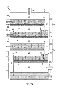
FIG. 2A shows, according to some embodiments, a schematic illustration of an
exemplary desalination system comprising a vessel comprising a multi-stage
humidification
region and a multi-stage dehumidification region;
CA 02986577 2017-11-20
WO 2016/187601
PCT/US2016/033667
- 8 -
FIG. 2B shows, according to some embodiments, a schematic illustration of an
exemplary desalination system comprising a vessel comprising a multi-stage
humidification
region, a multi-stage dehumidification region, and an intermediate gas
injection point;
FIG. 2C shows, according to some embodiments, a schematic illustration of an
exemplary desalination system comprising a vessel comprising a multi-stage
humidification
region, a multi-stage dehumidification region, and an intermediate gas
extraction point
fluidically connected to an intermediate gas injection point;
FIG. 2D shows, according to some embodiments, a schematic illustration of an
exemplary desalination system comprising a vessel comprising a multi-stage
humidification
region, a multi-stage dehumidification region, two droplet eliminators, and a
liquid collector;
FIG. 2E shows, according to some embodiments, a schematic illustration of an
exemplary
desalination system comprising a vessel comprising a multi-stage
humidification region, a multi-
stage dehumidification region, two droplet eliminators, a liquid collector,
and an external sump;
FIG. 3A shows a schematic illustration of an exemplary desalination system
comprising a
vessel comprising a humidification region comprising a plurality of vertically-
arranged stages
positioned horizontally adjacent to a dehumidification region comprising a
plurality of vertically-
arranged stages, according to some embodiments;
FIG. 3B shows a schematic illustration of an exemplary desalination system
comprising a
vessel comprising a humidification region and a dehumidification region, a
main internal gas
conduit fluidically connected to a main gas outlet of the humidification
region and a main gas
inlet of the dehumidification region, and an auxiliary internal gas conduit
fluidically connected to
an intermediate gas outlet of the humidification region and an intermediate
gas inlet of the
dehumidification region, according to some embodiments;
FIG. 4 shows, according to some embodiments, a schematic illustration of an
exemplary
desalination system comprising a vessel comprising a humidification region
comprising a
plurality of horizontally-arranged stages positioned horizontally adjacent to
a dehumidification
region comprising a plurality of horizontally-arranged stages;
FIG. 5 shows a schematic illustration of an exemplary desalination system
configured for
batch processing, according to some embodiments;
FIG. 6A shows, according to some embodiments, a schematic illustration of an
exemplary baffle;
CA 02986577 2017-11-20
WO 2016/187601
PCT/US2016/033667
- 9 -
FIG. 6B shows, according to some embodiments, a schematic illustration of an
exemplary weaving baffle;
FIGS. 7A-C show schematic illustrations of an exemplary combined HDH apparatus
comprising an integrated wheel base, according to some embodiments;
FIG. 8A shows, according to some embodiments, a schematic illustration of an
exemplary combined HDH apparatus positioned on a flatbed shipping trailer;
FIG. 8B shows, according to some embodiments, a schematic illustration of an
exemplary combined HDH apparatus positioned on a stepdeck shipping trailer;
FIG. 8C shows, according to some embodiments, a schematic illustration of an
exemplary combined HDH apparatus positioned on a lowboy shipping trailer;
FIG. 9A shows a schematic illustration of an exemplary system comprising a
humidifier
positioned on a first flatbed shipping trailer and a dehumidifier positioned
on a second flatbed
shipping trailer, according to some embodiments;
FIG. 9B shows a schematic illustration of an exemplary system comprising a
humidifier
positioned on a first stepdeck shipping trailer and a dehumidifier positioned
on a second stepdeck
shipping trailer, according to some embodiments;
FIG. 9C shows a schematic illustration of an exemplary system comprising a
humidifier
positioned on a first lowboy shipping trailer and a dehumidifier positioned on
a second lowboy
shipping trailer, according to some embodiments;
FIG. 10A shows a schematic diagram of an exemplary desalination system
comprising a
combined HDH apparatus and an external heat exchanger, according to some
embodiments;
FIG. 10B shows a schematic diagram of an exemplary desalination system
comprising a
combined HDH apparatus, an external heat exchanger, an external cooling
device, and an
external heating device, according to some embodiments;
FIG. 11 shows a schematic diagram, according to some embodiments, of an
exemplary
system comprising a pretreatment system, a desalination system, and a
precipitation apparatus;
FIG. 12 shows, according to some embodiments, a schematic diagram of an
exemplary
desalination system comprising a central feed tank, a common heating fluid
source, and two
HDH desalination units, each HDH desalination unit comprising a humidifier, a
dehumidifier, a
first heat exchanger, and a second heat exchanger; and
CA 02986577 2017-11-20
WO 2016/187601
PCT/US2016/033667
- 10 -
FIG. 13 shows, according to some embodiments, a schematic illustration of an
exemplary
desalination system comprising an apparatus comprising a humidification region
and a
dehumidification region, a precipitation apparatus, a first heat exchanger, a
second heating
exchanger, and a cooling device.
DETAILED DESCRIPTION
Certain embodiments described herein generally relate to apparatuses that
include a
vessel comprising a humidification region (e.g., a bubble column
humidification region) and a
dehumidification region (e.g., a bubble column dehumidification region), and
associated systems
and methods. In certain embodiments, the apparatuses are configured to include
various internal
features, such as vapor distribution regions and/or liquid flow control weirs
and/or baffles. In
some embodiments, mobile humidification-dehumidification (HDH) desalination
systems are
described that comprise a humidifier (e.g., a bubble column humidifier) having
a relatively low
height and/or a relatively small footprint and/or a dehumidifier (e.g., a
bubble column condenser)
having a relatively low height and/or a relatively small footprint. In some
embodiments, the
mobile HDH desalination system comprises a vessel comprising a humidification
region (e.g., a
bubble column humidification region) and a dehumidification region (e.g., a
bubble column
dehumidification region), where the vessel has a relatively low height and/or
a relatively small
footprint. In certain cases, the relatively low height and/or relatively small
footprint may
facilitate transport and/or installation of the HDH desalination system. In
some cases, the
systems described herein allow for simplified, lower cost systems with
improved performance
(e.g., higher thermodynamic efficiency). According to some embodiments, the
apparatuses may
be used in water purification systems, such as desalination systems. The water
purification
systems may comprise additional devices external to the apparatuses, such as
one or more heat
exchangers, one or more heating devices, and/or one or more cooling devices.
Certain
embodiments generally relate to methods of operating, controlling, and/or
cleaning desalination
systems comprising a plurality of desalination units (e.g., HDH desalination
units).
While generally embodiments of the invention may employ a variety of
humidifier and
dehumidifier designs, including but not limited to those involving direct
contact between gas and
liquid phases, in some embodiments, bubble column humidifiers and bubble
column
dehumidifiers are described, which may be associated with certain advantages
over certain other
CA 02986577 2017-11-20
WO 2016/187601
PCT/US2016/033667
- 11 -
types of humidifiers and dehumidifiers. For example, bubble column humidifiers
and
dehumidifiers may exhibit higher thermodynamic efficiency than certain other
types of
humidifiers (e.g., packed bed humidifiers, spray towers, wetted wall towers)
and dehumidifiers
(e.g., surface condensers). Without wishing to be bound by a particular
theory, the increased
thermodynamic efficiency may be at least partially attributed to the use of
gas bubbles for heat
and mass transfer in bubble column humidifiers and dehumidifiers, since gas
bubbles may have
more surface area available for heat and mass transfer than other types of
surfaces (e.g., metallic
tubes, liquid films, packing material). As described in further detail herein,
a bubble column
humidifier and/or dehumidifier may have certain features that further increase
thermodynamic
efficiency, including, but not limited to, relatively low liquid level height,
relatively high aspect
ratio liquid flow paths, and multi-staged designs. As a result of their
increased thermodynamic
efficiency, bubble column humidifiers and/or dehumidifiers having a certain
capacity may be
reduced in size compared to other types of humidifiers and/or dehumidifiers
having the same
capacity. In a particular, non-limiting example, a bubble column humidifier
having a height of 8
feet and a certain diameter may be capable of replacing two packed bed
humidifier towers
having a combined height of 25 feet and the same diameter.
It has been recognized within the context of this invention that it may be
advantageous to
combine both a humidification region, for example a bubble column
humidification region, and a
dehumidification region, for example a bubble column dehumidification region,
into a single
vessel of an apparatus. A vessel generally refers to any structure (e.g., a
tank) capable of
housing a humidification region and a dehumidification region. In some cases,
a combined
humidification-dehumidification (HDH) apparatus (e.g., an apparatus comprising
a vessel
comprising a humidification region and a dehumidification region) may have
fewer components
and/or use less material than an HDH system comprising a separate humidifier
(e.g., a bubble
column humidifier) and a separate dehumidifier (e.g., a bubble column
dehumidifier). For
example, an HDH system comprising a separate humidifier and dehumidifier may
require one or
more ducts (e.g., for gas flow) and/or pipes (e.g., for liquid flow)
connecting the humidifier and
dehumidifier. In certain cases, the ducts and/or pipes may be expensive and/or
burdensome to
install. For example, in some industrial facilities (e.g., oil and gas
facilities) that are located in
remote areas, system components may be built off-site as deployable skids. If
a humidifier
resides on one skid and a dehumidifier resides on another skid, ducting and/or
piping
CA 02986577 2017-11-20
WO 2016/187601
PCT/US2016/033667
- 12 -
connections may need to be made during on-site installation, which may
lengthen the time
required for system deployment. In contrast, ducting and/or piping may be
reduced or eliminated
in a combined HDH apparatus (e.g., a combined bubble column apparatus). For
example, a
combined HDH apparatus may eliminate the need for ducting between a humidifier
gas outlet
and a dehumidifier gas inlet. In certain embodiments, the combined HDH
apparatus comprises
one or more gas conduits (e.g., internal gas conduits) in fluid communication
with the
humidification region and the dehumidification region of the apparatus. In
some cases, for
example, the one or more gas conduits (e.g., internal gas conduits) are in
fluid communication
with a gas outlet (e.g., a main gas outlet) of the humidification region and a
gas inlet (e.g., a main
gas inlet) of the dehumidification region. In some embodiments, the combined
HDH apparatus
further comprises one or more auxiliary gas conduits (e.g., internal auxiliary
gas conduits) in
fluid communication with an intermediate gas outlet of the humidification
region and an
intermediate gas inlet of the dehumidification region. To the extent that
ducting is still required,
the gas inlets and outlets may be positioned closer together, resulting in
less ducting than in
HDH systems comprising separate humidifiers and dehumidifiers. This may be
advantageous,
since ducting used to transport heated, humidified gas in an HDH system may be
relatively
expensive, large, heavy, and/or rigid. For example, one suitable type of
ducting is stainless steel
with fiberglass insulation, which is generally capable of accommodating high
gas flow rates at
high temperatures and/or withstanding potentially corrosive environments.
Installation of such
ducting may be challenging due to its relatively large size, heavy weight,
and/or high rigidity.
Similarly, a combined HDH apparatus may require less piping (e.g., for liquid
flow) than an
HDH system comprising separate humidifiers and dehumidifiers, since liquid
inlets and outlets
may be positioned in closer proximity to each other. Any required piping may
comprise hard
pipes, flexible hoses, or any other type of suitable piping known in the art.
In addition to eliminated or reduced ducting and/or piping, a combined HDH
apparatus
(e.g. combined bubble column apparatus) may have additional features that
allow it to take up
less space and/or use fewer materials than an HDH system comprising a separate
humidifier and
dehumidifier. For example, a combined HDH apparatus may require less space for
walkways
and/or maintenance points since components may be positioned closer together.
In some cases, a
combined HDH apparatus may also require less insulating material. For example,
an HDH
CA 02986577 2017-11-20
WO 2016/187601
PCT/US2016/033667
- 13 -
system comprising a separate humidifier and dehumidifier may have additional
walls to be
insulated compared to a combined HDH apparatus.
Other aspects of a combined HDH apparatus (e.g. combined bubble column
apparatus)
may further reduce cost. For example, the humidification and dehumidification
regions of a
combined HDH apparatus may have structural similarities, which may
advantageously allow
certain parts to be used in both the humidification and dehumidification
regions. Due to
economies of scale, a decrease in the number of unique parts in an HDH system
may
advantageously reduce the cost of the HDH system. Reducing the number of
unique parts may
also simplify the production process.
According to some embodiments of the invention, an apparatus (e.g., a combined
bubble
column apparatus) comprises a vessel, and the vessel comprises a
humidification region (e.g., a
bubble column humidification region) and a dehumidification region (e.g., a
bubble column
dehumidification region). The humidification region may be configured to
receive a
humidification region gas inlet stream from a source of a gas via at least one
humidification
region gas inlet. In some cases, the gas comprises at least one non-
condensable gas. A non-
condensable gas generally refers to a gas that cannot be condensed from gas
phase to liquid
phase under the operating conditions of the apparatus. Examples of suitable
non-condensable
gases include, but are not limited to, air, nitrogen, oxygen, helium, argon,
carbon monoxide,
carbon dioxide, sulfur oxides (SO) (e.g., SO2, SO3), and/or nitrogen oxides
(NO) (e.g., NO,
NO2). In some embodiments, in addition to the at least one non-condensable
gas, the gas further
comprises one or more additional gases (e.g., the gas may be a gas mixture).
The humidification region may also be configured to receive a humidification
region
liquid inlet stream (e.g., liquid feed stream) from a source of a liquid via
at least one
humidification region liquid inlet. In some embodiments, the liquid comprises
a condensable
fluid in liquid phase. A condensable fluid generally refers to a fluid that is
able to condense from
gas phase to liquid phase under the operating conditions of the apparatus. Non-
limiting,
illustrative examples of suitable condensable fluids include water, ammonia,
benzene, toluene,
ethyl benzene, and/or alcohols. In addition to the condensable fluid in liquid
phase, the liquid
may further comprise one or more additional liquids (e.g., the liquid may be a
liquid mixture). In
some embodiments, the liquid further comprises one or more contaminants. The
one or more
contaminants may, for example, comprise one or more dissolved salts. A
dissolved salt
CA 02986577 2017-11-20
WO 2016/187601
PCT/US2016/033667
- 14 -
generally refers to a salt that has been solubilized to such an extent that
the component ions (e.g.,
an anion, a cation) of the salt are no longer ionically bonded to each other.
Non-limiting
examples of dissolved salts that may be present in the liquid include sodium
chloride (NaC1),
sodium bromide (NaBr), potassium chloride (KC1), potassium bromide (KBr),
ammonium
chloride (NH4C1), calcium chloride (CaC12), magnesium chloride (MgC12), sodium
carbonate
(Na2CO3), ), sodium bicarbonate (NaHCO3), potassium bicarbonate (KHCO3),
sodium sulfate
(Na2SO4), potassium sulfate (K2SO4), calcium sulfate (CaSO4), magnesium
sulfate (MgSO4),
strontium sulfate (SrSO4), barium sulfate (BaSO4), barium-strontium sulfate
(BaSr(SO4)2),
calcium nitrate (Ca(NO3)2), iron (III) hydroxide (Fe(OH)3), iron (III)
carbonate (Fe2(CO3)3),
aluminum hydroxide (Al(OH)3), aluminum carbonate (Al2(CO3)3), ammonium
bicarbonate,
ammonium sulfate, boron salts, polyacrylic acid sodium salts, and/or
silicates.
In a particular embodiment, the liquid comprises salt-containing water (e.g.,
water
comprising one or more dissolved salts). In certain cases, the salt-containing
water comprises
seawater, brackish water, water produced form an oil and/or gas extraction
process, flowback
water, and/or wastewater (e.g., industrial wastewater). Non-limiting examples
of wastewater
include textile mill wastewater, leather tannery wastewater, paper mill
wastewater, cooling tower
blowdown water, flue gas desulfurization wastewater, landfill leachate water,
and/or the effluent
of a chemical process (e.g., the effluent of another desalination system
and/or chemical process).
In some embodiments, the humidification region liquid inlet stream has a
relatively high
concentration of one or more contaminants (e.g., dissolved salts). In certain
embodiments, the
concentration of one or more contaminants in the humidification region liquid
inlet stream is at
least about 100 mg/L, at least about 200 mg/L, at least about 500 mg/L, at
least about 1,000
mg/L, at least about 2,000 mg/L, at least about 5,000 mg/L, at least about
10,000 mg/L, at least
about 20,000 mg/L, at least about 50,000 mg/L, at least about 75,000 mg/L, at
least about
100,000 mg/L, at least about 102,000 mg/L, at least about 110,000 mg/L, at
least about 120,000
mg/L, at least about 150,000 mg/L, at least about 175,000 mg/L, at least about
200,000 mg/L, at
least about 210,000 mg/L, at least about 219,000 mg/L, at least about 220,000
mg/L, at least
about 250,000 mg/L, at least about 275,000 mg/L, at least about 300,000 mg/L,
at least about
310,000 mg/L, at least about 312,000 mg/L, at least about 320,000 mg/L, at
least about 350,000
mg/L, or at least about 375,000 mg/L (and/or, in certain embodiments, up to
the solubility limit
of the one or more contaminants in the liquid stream). In some embodiments,
the concentration
CA 02986577 2017-11-20
WO 2016/187601
PCT/US2016/033667
- 15 -
of one or more contaminants in the humidification region liquid inlet stream
is in the range of
about 100 mg/L to about 375,000 mg/L, about 1,000 mg/L to about 10,000 mg/L,
about 1,000
mg/L to about 50,000 mg/L, about 1,000 mg/L to about 75,000 mg/L, about 1,000
mg/L to about
100,000 mg/L, about 1,000 mg/L to about 150,000 mg/L, about 1,000 mg/L to
about 200,000
mg/L, about 1,000 mg/L to about 250,000 mg/L, about 1,000 mg/L to about
300,000 mg/L, about
1,000 mg/L to about 350,000 mg/L, about 1,000 mg/L to about 375,000 mg/L,
about 10,000
mg/L to about 50,000 mg/L, about 10,000 mg/L to about 75,000 mg/L, about
10,000 mg/L to
about 100,000 mg/L, about 10,000 mg/L to about 150,000 mg/L, about 10,000 mg/L
to about
200,000 mg/L, about 10,000 mg/L to about 250,000 mg/L, about 10,000 mg/L to
about 300,000
mg/L, about 10,000 mg/L to about 350,000 mg/L, about 10,000 mg/L to about
375,000 mg/L,
about 50,000 mg/L to about 100,000 mg/L, about 50,000 mg/L to about 150,000
mg/L, about
50,000 mg/L to about 200,000 mg/L, about 50,000 mg/L to about 250,000 mg/L,
about 50,000
mg/L to about 300,000 mg/L, about 50,000 mg/L to about 350,000 mg/L, about
50,000 mg/L to
about 375,000 mg/L, about 100,000 mg/L to about 150,000 mg/L, about 100,000
mg/L to about
200,000 mg/L, about 100,000 mg/L to about 250,000 mg/L, about 100,000 mg/L to
about
300,000 mg/L, about 100,000 mg/L to about 350,000 mg/L, about 100,000 mg/L to
about
375,000 mg/L, about 102,000 mg/L to about 219,000 mg/L, about 102,000 mg/L to
about
312,000 mg/L, about 150,000 mg/L to about 200,000 mg/L, about 150,000 mg/L to
about
250,000 mg/L, about 150,000 mg/L to about 300,000 mg/L, about 150,000 mg/L to
about
350,000 mg/L, about 150,000 mg/L to about 375,000 mg/L, about 200,000 mg/L to
about
250,000 mg/L, about 200,000 mg/L to about 300,000 mg/L, about 200,000 mg/L to
about
350,000 mg/L, about 200,000 mg/L to about 375,000 mg/L, about 250,000 mg/L to
about
300,000 mg/L, about 250,000 mg/L to about 350,000 mg/L, about 250,000 mg/L to
about
375,000 mg/L, about 300,000 mg/L to about 350,000 mg/L, or about 300,000 mg/L
to about
375,000 mg/L. As noted above, the one or more contaminants may comprise one or
more
dissolved salts (e.g., NaC1). The concentration of a dissolved salt generally
refers to the
combined concentrations of the cation and the anion of the salt. For example,
the concentration
of dissolved NaC1 would refer to the sum of the concentration of sodium ions
(Nat) and the
concentration of chloride ions (Cl). The concentration of a contaminant (e.g.,
a dissolved salt)
may be measured according to any method known in the art. For example, methods
for
measuring the concentration of a contaminant include inductively coupled
plasma (ICP)
CA 02986577 2017-11-20
WO 2016/187601
PCT/US2016/033667
- 16 -
spectroscopy (e.g., inductively coupled plasma optical emission spectroscopy).
As one non-
limiting example, an Optima 8300 ICP-OES spectrometer may be used.
In some embodiments, the humidification region liquid inlet stream contains at
least one
contaminant (e.g., dissolved salt) in an amount of at least about 1 wt%, at
least about 5 wt%, at
least about 10 wt%, at least about 15 wt%, at least about 20 wt%, at least
about 25 wt%, at least
about 26 wt%, at least about 27 wt%, at least about 28 wt%, at least about 29
wt%, or at least
about 30 wt% (and/or, in certain embodiments, up to the solubility limit of
the at least one
contaminant in the liquid stream). In some embodiments, the humidification
region liquid inlet
stream comprises at least one contaminant in an amount in the range of about 1
wt% to about 10
wt%, about 1 wt% to about 20 wt%, about 1 wt% to about 25 wt%, about 1 wt% to
about 26
wt%, about 1 wt% to about 27 wt%, about 1 wt% to about 28 wt%, about 1 wt% to
about 29
wt%, about 1 wt% to about 30 wt%, about 10 wt% to about 20 wt%, about 10 wt%
to about 25
wt%, about 10 wt% to about 26 wt%, about 10 wt% to about 27 wt%, about 10 wt%
to about 28
wt%, about 10 wt% to about 29 wt%, about 10 wt% to about 30 wt%, about 20 wt%
to about 25
wt%, about 20 wt% to about 26 wt%, about 20 wt% to about 27 wt%, about 20 wt%
to about 28
wt%, about 20 wt% to about 29 wt%, about 20 wt% to about 30 wt%, about 25 wt%
to about 26
wt%, about 25 wt% to about 27 wt%, about 25 wt% to about 28 wt%, about 25 wt%
to about 29
wt%, or about 25 wt% to about 30 wt%.
According to some embodiments, the humidification region liquid inlet stream
has a
relatively high total contaminant concentration (e.g., concentration of all
contaminants present in
the liquid stream). In certain cases, the total contaminant concentration of
the humidification
region liquid inlet stream is at least about 1,000 mg/L, at least about 2,000
mg/L, at least about
5,000 mg/L, at least about 10,000 mg/L, at least about 20,000 mg/L, at least
about 50,000 mg/L,
at least about 75,000 mg/L, at least about 100,000 mg/L, at least about
110,000 mg/L, at least
about 120,000 mg/L, at least about 150,000 mg/L, at least about 175,000 mg/L,
at least about
200,000 mg/L, at least about 210,000 mg/L, at least about 220,000 mg/L, at
least about 250,000
mg/L, at least about 275,000 mg/L, at least about 300,000 mg/L, at least about
310,000 mg/L, at
least about 320,000 mg/L, at least about 350,000 mg/L, at least about 375,000
mg/L, at least
about 400,000 mg/L, at least about 450,000 mg/L, or at least about 500,000
mg/L (and/or, in
certain embodiments, up to the solubility limit of the dissolved
contaminant(s) in the liquid
stream). In some embodiments, the total contaminant concentration of the
humidification region
CA 02986577 2017-11-20
WO 2016/187601
PCT/US2016/033667
- 17 -
liquid inlet stream is in the range of about 1,000 mg/L to about 10,000 mg/L,
about 1,000 mg/L
to about 20,000 mg/L, about 1,000 mg/L to about 50,000 mg/L, about 1,000 mg/L
to about
75,000 mg/L, about 1,000 mg/L to about 100,000 mg/L, about 1,000 mg/L to about
150,000
mg/L, about 1,000 mg/L to about 200,000 mg/L, about 1,000 mg/L to about
250,000 mg/L, about
1,000 mg/L to about 300,000 mg/L, about 1,000 mg/L to about 350,000 mg/L,
about 1,000 mg/L
to about 400,000 mg/L, about 1,000 mg/L to about 450,000 mg/L, about 1,000
mg/L to about
500,000 mg/L, about 10,000 mg/L to about 20,000 mg/L, about 10,000 mg/L to
about 50,000
mg/L, about 10,000 mg/L to about 75,000 mg/L, about 10,000 mg/L to about
100,000 mg/L,
about 10,000 mg/L to about 150,000 mg/L, about 10,000 mg/L to about 200,000
mg/L, about
10,000 mg/L to about 250,000 mg/L, about 10,000 mg/L to about 300,000 mg/L,
about 10,000
mg/L to about 350,000 mg/L, about 10,000 mg/L to about 400,000 mg/L, about
10,000 mg/L to
about 450,000 mg/L, about 10,000 mg/L to about 500,000 mg/L, about 20,000 mg/L
to about
50,000 mg/L, about 20,000 mg/L to about 75,000 mg/L, about 20,000 mg/L to
about 100,000
mg/L, about 20,000 mg/L to about 150,000 mg/L, about 20,000 mg/L to about
200,000 mg/L,
about 20,000 mg/L to about 250,000 mg/L, about 20,000 mg/L to about 300,000
mg/L, about
20,000 mg/L to about 350,000 mg/L, about 20,000 mg/L to about 400,000 mg/L,
about 20,000
mg/L to about 450,000 mg/L, about 20,000 mg/L to about 500,000 mg/L, about
50,000 mg/L to
about 100,000 mg/L, about 50,000 mg/L to about 150,000 mg/L, about 50,000 mg/L
to about
200,000 mg/L, about 50,000 mg/L to about 250,000 mg/L, about 50,000 mg/L to
about 300,000
mg/L, about 50,000 mg/L to about 350,000 mg/L, about 50,000 mg/L to about
400,000 mg/L,
about 50,000 mg/L to about 450,000 mg/L, about 50,000 mg/L to about 500,000
mg/L, about
100,000 mg/L to about 150,000 mg/L, about 100,000 mg/L to about 200,000 mg/L,
about
100,000 mg/L to about 250,000 mg/L, about 100,000 mg/L to about 300,000 mg/L,
about
100,000 mg/L to about 350,000 mg/L, about 100,000 mg/L to about 400,000 mg/L,
about
100,000 mg/L to about 450,000 mg/L, or about 100,000 mg/L to about 500,000
mg/L.
In some embodiments, the contaminants present in the humidification region
liquid inlet
stream comprise two or more dissolved salts. The concentration of a plurality
of dissolved salts
generally refers to the combined concentrations of all the cations and anions
of the dissolved
salts. As a simple, non-limiting example, in a liquid stream comprising
dissolved NaC1 and
dissolved MgSO4, the total dissolved salt concentration would refer to the sum
of the
concentrations of the Nat, a-, Me, and S042- ions. The total contaminant
concentration may
CA 02986577 2017-11-20
WO 2016/187601
PCT/US2016/033667
- 18 -
be measured according to any method known in the art. For example, a non-
limiting example of
a suitable method for measuring total contaminant concentration is the SM
2540C method.
According to the SM 2540C method, a sample comprising an amount of liquid
comprising one or
more dissolved solids is filtered (e.g., through a glass fiber filter), and
the filtrate is evaporated to
dryness in a weighed dish at 180 C. The increase in dish weight represents
the mass of the total
dissolved solids in the sample. The total contaminant concentration of the
sample may be
obtained by dividing the mass of the total dissolved solids by the volume of
the original sample.
In some embodiments, the humidification region liquid inlet stream has a total
contaminant concentration of at least about 1 wt%, at least about 5 wt%, at
least about 10 wt%,
at least about 15 wt%, at least about 20 wt%, at least about 25 wt%, at least
about 26 wt%, at
least about 27 wt%, at least about 28 wt%, at least about 29 wt%, or at least
about 30 wt%
(and/or, in certain embodiments, up to the solubility limit of the dissolved
contaminant(s) in the
liquid stream). In some embodiments, the humidification region liquid inlet
stream has a total
contaminant concentration in the range of about 1 wt% to about 10 wt%, about 1
wt% to about
20 wt%, about 1 wt% to about 25 wt%, about 1 wt% to about 26 wt%, about 1 wt%
to about 27
wt%, about 1 wt% to about 28 wt%, about 1 wt% to about 29 wt%, about 1 wt% to
about 30
wt%, about 10 wt% to about 20 wt%, about 10 wt% to about 25 wt%, about 10 wt%
to about 26
wt%, about 10 wt% to about 27 wt%, about 10 wt% to about 28 wt%, about 10 wt%
to about 29
wt%, about 10 wt% to about 30 wt%, about 20 wt% to about 25 wt%, about 20 wt%
to about 26
wt%, about 20 wt% to about 27 wt%, about 20 wt% to about 28 wt%, about 20 wt%
to about 29
wt%, about 20 wt% to about 30 wt%, about 25 wt% to about 26 wt%, about 25 wt%
to about 27
wt%, about 25 wt% to about 28 wt%, about 25 wt% to about 29 wt%, or about 25
wt% to about
wt%.
In some embodiments, the humidification region is configured to receive the
25 humidification region liquid inlet stream at a relatively high rate. In
some embodiments, the
humidification region receives the humidification region liquid inlet stream
at a rate of at least
about 40 gpm, at least about 50 gpm, at least about 100 gpm, at least about
150 gpm, at least
about 200 gpm, at least about 300 gpm, at least about 400 gpm, at least about
500 gpm, at least
about 600 gpm, at least about 700 gpm, at least about 800 gpm, at least about
900 gpm, at least
30 about 1000 gpm, at least about 1100 gpm, at least about 1200 gpm, at
least about 1300 gpm, at
least about 1400 gpm, at least about 1500 gpm, at least about 2000 gpm, at
least about 2500 gpm,
CA 02986577 2017-11-20
WO 2016/187601
PCT/US2016/033667
- 19 -
at least about 3000 gpm, at least about 3500 gpm, or at least about 4000 gpm.
In some
embodiments, the humidification region receives the humidification region
liquid inlet stream at
a rate of about 40 gpm to about 100 gpm, about 40 gpm to about 150 gpm, about
40 gpm to
about 200 gpm, about 40 gpm to about 500 gpm, about 40 gpm to about 1000 gpm,
about 40
gpm to about 1500 gpm, about 40 gpm to about 2000 gpm, about 40 gpm to about
2500 gpm,
about 40 gpm to about 3000 gpm, about 40 gpm to about 3500 gpm, about 40 gpm
to about 4000
gpm, about 100 gpm to about 150 gpm, about 100 gpm to about 200 gpm, about 100
gpm to
about 500 gpm, about 100 gpm to about 1000 gpm, about 100 gpm to about 1500
gpm, about
100 gpm to about 2000 gpm, about 100 gpm to about 2500 gpm, about 100 gpm to
about 3000
gpm, about 100 gpm to about 3500 gpm, about 100 gpm to about 4000 gpm, about
150 gpm to
about 200 gpm, about 150 gpm to about 500 gpm, about 150 gpm to about 1000
gpm, about 150
gpm to about 1500 gpm, about 150 gpm to about 2000 gpm, about 150 gpm to about
2500 gpm,
about 150 gpm to about 3000 gpm, about 150 gpm to about 3500 gpm, about 150
gpm to about
4000 gpm, about 200 gpm to about 500 gpm, about 200 gpm to about 1000 gpm,
about 200 gpm
to about 1500 gpm, about 200 gpm to about 2000 gpm, about 200 gpm to about
2500 gpm, about
200 gpm to about 3000 gpm, about 200 gpm to about 3500 gpm, about 200 gpm to
about 4000
gpm, about 500 gpm to about 1000 gpm, about 500 gpm to about 1500 gpm, about
500 gpm to
about 2000 gpm, about 500 gpm to about 2500 gpm, about 500 gpm to about 3000
gpm, about
500 gpm to about 3500 gpm, about 500 gpm to about 4000 gpm, about 1000 gpm to
about 1500
gpm, about 1000 gpm to about 2000 gpm, about 1000 gpm to about 2500 gpm, about
1000 gpm
to about 3000 gpm, about 1000 gpm to about 3500 gpm, about 1000 gpm to about
4000 gpm,
about 1500 gpm to about 2000 gpm, about 1500 gpm to about 2500 gpm, about 1500
gpm to
about 3000 gpm, about 1500 gpm to about 3500 gpm, about 1500 gpm to about 4000
gpm, about
2000 gpm to about 3000 gpm, about 2000 gpm to about 4000 gpm, or about 3000
gpm to about
4000 gpm. In certain embodiments, the humidification region receives the
humidification region
liquid inlet stream at a rate of about 150 gpm to about 1500 gpm.
In the humidification region, the gas may come into contact (e.g., direct or
indirect
contact) with the liquid. In some embodiments, the temperature of the liquid
is higher than the
temperature of the gas, and upon contact of the gas and the liquid, heat
and/or mass may be
transferred from the liquid to the gas. According to certain embodiments, at
least a portion of the
condensable fluid in the liquid is transferred to the gas via an evaporation
(e.g., humidification)
CA 02986577 2017-11-20
WO 2016/187601
PCT/US2016/033667
- 20 -
process, thereby producing a vapor-containing humidification region gas outlet
stream (e.g., an at
least partially humidified gas stream) and a humidification region liquid
outlet stream. In some
embodiments, the humidification region gas outlet stream comprises a vapor
mixture (e.g., a
mixture of the condensable fluid in vapor phase and the non-condensable gas).
In certain cases,
the condensable fluid is water, and the humidification region gas outlet
stream is enriched in
water vapor relative to the gas received from the humidification region gas
inlet. In some
embodiments, the humidification region liquid outlet stream has a higher
concentration of one or
more contaminants (e.g., dissolved salts) than the humidification region
liquid inlet stream (e.g.,
the humidification region liquid outlet stream is enriched in the one or more
contaminants
relative to the humidification region liquid inlet stream).
According to some embodiments, the humidification region liquid outlet stream
has a
relatively high concentration of one or more contaminants (e.g., dissolved
salts). In certain
embodiments, the concentration of one or more contaminants in the
humidification region liquid
outlet stream is at least about 100 mg/L, at least about 200 mg/L, at least
about 500 mg/L, at least
about 1,000 mg/L, at least about 2,000 mg/L, at least about 5,000 mg/L, at
least about 10,000
mg/L, at least about 20,000 mg/L, at least about 50,000 mg/L, at least about
75,000 mg/L, at
least about 100,000 mg/L, at least about 150,000 mg/L, at least about 200,000
mg/L, at least
about 250,000 mg/L, at least about 300,000 mg/L, at least about 350,000 mg/L,
at least about
400,000 mg/L, at least about 450,000 mg/L, or at least about 500,000 mg/L
(and/or, in certain
embodiments, up to the solubility limit of the one or more contaminants in the
liquid stream). In
some embodiments, the concentration of one or more contaminants in the
humidification region
liquid outlet stream is in the range of about 1,000 mg/L to about 10,000 mg/L,
about 1,000 mg/L
to about 20,000 mg/L, about 1,000 mg/L to about 50,000 mg/L, about 1,000 mg/L
to about
100,000 mg/L, about 1,000 mg/L to about 150,000 mg/L, about 1,000 mg/L to
about 200,000
mg/L, about 1,000 mg/L to about 250,000 mg/L, about 1,000 mg/L to about
300,000 mg/L, about
1,000 mg/L to about 350,000 mg/L, about 1,000 mg/L to about 400,000 mg/L,
about 1,000 mg/L
to about 450,000 mg/L, about 1,000 mg/L to about 500,000 mg/L, about 10,000
mg/L to about
20,000 mg/L, about 10,000 mg/L to about 50,000 mg/L, about 10,000 mg/L to
about 100,000
mg/L, about 10,000 mg/L to about 150,000 mg/L, about 10,000 mg/L to about
200,000 mg/L,
about 10,000 mg/L to about 250,000 mg/L, about 10,000 mg/L to about 300,000
mg/L, about
10,000 mg/L to about 350,000 mg/L, about 10,000 mg/L to about 400,000 mg/L,
about 10,000
CA 02986577 2017-11-20
WO 2016/187601
PCT/US2016/033667
-21 -
mg/L to about 450,000 mg/L, about 10,000 mg/L to about 500,000 mg/L, about
20,000 mg/L to
about 50,000 mg/L, about 20,000 mg/L to about 100,000 mg/L, about 20,000 mg/L
to about
150,000 mg/L, about 20,000 mg/L to about 200,000 mg/L, about 20,000 mg/L to
about 250,000
mg/L, about 20,000 mg/L to about 300,000 mg/L, about 20,000 mg/L to about
350,000 mg/L,
about 20,000 mg/L to about 400,000 mg/L, about 20,000 mg/L to about 450,000
mg/L, about
20,000 mg/L to about 500,000 mg/L, about 50,000 mg/L to about 100,000 mg/L,
about 50,000
mg/L to about 150,000 mg/L, about 50,000 mg/L to about 200,000 mg/L, about
50,000 mg/L to
about 250,000 mg/L, about 50,000 mg/L to about 300,000 mg/L, about 50,000 mg/L
to about
350,000 mg/L, about 50,000 mg/L to about 400,000 mg/L, about 50,000 mg/L to
about 450,000
mg/L, about 50,000 mg/L to about 500,000 mg/L, about 100,000 mg/L to about
150,000 mg/L,
about 100,000 mg/L to about 200,000 mg/L, about 100,000 mg/L to about 250,000
mg/L, about
100,000 mg/L to about 300,000 mg/L, about 100,000 mg/L to about 350,000 mg/L,
about
100,000 mg/L to about 400,000 mg/L, about 100,000 mg/L to about 450,000 mg/L,
or about
100,000 mg/L to about 500,000 mg/L.
In some embodiments, the humidification region liquid outlet stream contains
at least one
contaminant (e.g., dissolved salt) in an amount of at least about 1 wt%, at
least about 5 wt%, at
least about 10 wt%, at least about 15 wt%, at least about 20 wt%, at least
about 25 wt%, at least
about 26 wt%, at least about 27 wt%, at least about 28 wt%, at least about 29
wt%, or at least
about 30 wt% (and/or, in certain embodiments, up to the solubility limit of
the contaminant in the
liquid stream). In some embodiments, the humidification region liquid outlet
stream comprises
at least one contaminant in an amount in the range of about 1 wt% to about 10
wt%, about 1 wt%
to about 20 wt%, about 1 wt% to about 25 wt%, about 1 wt% to about 26 wt%,
about 1 wt% to
about 27 wt%, about 1 wt% to about 28 wt%, about 1 wt% to about 29 wt%, about
1 wt% to
about 30 wt%, about 10 wt% to about 20 wt%, about 10 wt% to about 25 wt%,
about 10 wt% to
about 26 wt%, about 10 wt% to about 27 wt%, about 10 wt% to about 28 wt%,
about 10 wt% to
about 29 wt%, about 10 wt% to about 30 wt%, about 20 wt% to about 25 wt%,
about 20 wt% to
about 26 wt%, about 20 wt% to about 27 wt%, about 20 wt% to about 28 wt%,
about 20 wt% to
about 29 wt%, about 20 wt% to about 30 wt%, about 25 wt% to about 26 wt%,
about 25 wt% to
about 27 wt%, about 25 wt% to about 28 wt%, about 25 wt% to about 29 wt%, or
about 25 wt%
to about 30 wt%.
CA 02986577 2017-11-20
WO 2016/187601
PCT/US2016/033667
- 22 -
In some embodiments, the concentration of one or more contaminants in the
humidification region liquid outlet stream is substantially greater than the
concentration of the
one or more contaminants in the humidification region liquid inlet stream
(e.g., liquid feed
stream) received by the apparatus. In some cases, the concentration of one or
more contaminants
in the humidification region liquid outlet stream is at least about 0.5%,
about 1%, about 2%,
about 5%, about 10%, about 15%, or about 20% greater than the concentration of
the one or
more contaminants in the humidification region liquid inlet stream.
According to some embodiments, the humidification region liquid outlet stream
has a
relatively high total contaminant concentration (e.g., concentration of all
contaminants present in
the liquid stream). In certain cases, the humidification region liquid outlet
stream has a total
contaminant concentration of at least about 1,000 mg/L, at least about 2,000
mg/L, at least about
5,000 mg/L, at least about 10,000 mg/L, at least about 20,000 mg/L, at least
about 50,000 mg/L,
at least about 75,000 mg/L, at least about 100,000 mg/L, at least about
150,000 mg/L, at least
about 200,000 mg/L, at least about 250,000 mg/L, at least about 300,000 mg/L,
at least about
350,000 mg/L, at least about 400,000 mg/L, at least about 450,000 mg/L, at
least about 500,000
mg/L, at least about 550,000 mg/L, or at least about 600,000 mg/L (and/or, in
certain
embodiments, up to the solubility limit of the contaminant(s) in the liquid
stream). In some
embodiments, the total contaminant concentration of the humidification region
liquid outlet
stream is in the range of about 10,000 mg/L to about 20,000 mg/L, about 10,000
mg/L to about
50,000 mg/L, about 10,000 mg/L to about 100,000 mg/L, about 10,000 mg/L to
about 150,000
mg/L, about 10,000 mg/L to about 200,000 mg/L, about 10,000 mg/L to about
250,000 mg/L,
about 10,000 mg/L to about 300,000 mg/L, about 10,000 mg/L to about 350,000
mg/L, about
10,000 mg/L to about 400,000 mg/L, about 10,000 mg/L to about 450,000 mg/L,
about 10,000
mg/L to about 500,000 mg/L, about 10,000 mg/L to about 550,000 mg/L, about
10,000 mg/L to
about 600,000 mg/L, about 20,000 mg/L to about 50,000 mg/L, about 20,000 mg/L
to about
100,000 mg/L, about 20,000 mg/L to about 150,000 mg/L, about 20,000 mg/L to
about 200,000
mg/L, about 20,000 mg/L to about 250,000 mg/L, about 20,000 mg/L to about
300,000 mg/L,
about 20,000 mg/L to about 350,000 mg/L, about 20,000 mg/L to about 400,000
mg/L, about
20,000 mg/L to about 450,000 mg/L, about 20,000 mg/L to about 500,000 mg/L,
about 20,000
mg/L to about 550,000 mg/L, about 20,000 mg/L to about 600,000 mg/L, about
50,000 mg/L to
about 100,000 mg/L, about 50,000 mg/L to about 150,000 mg/L, about 50,000 mg/L
to about
CA 02986577 2017-11-20
WO 2016/187601
PCT/US2016/033667
-23 -
200,000 mg/L, about 50,000 mg/L to about 250,000 mg/L, about 50,000 mg/L to
about 300,000
mg/L, about 50,000 mg/L to about 350,000 mg/L, about 50,000 mg/L to about
400,000 mg/L,
about 50,000 mg/L to about 450,000 mg/L, about 50,000 mg/L to about 500,000
mg/L, about
50,000 mg/L to about 550,000 mg/L, about 50,000 mg/L to about 600,000 mg/L,
about 100,000
mg/L to about 200,000 mg/L, about 100,000 mg/L to about 250,000 mg/L, about
100,000 mg/L
to about 300,000 mg/L, about 100,000 mg/L to about 350,000 mg/L, about 100,000
mg/L to
about 400,000 mg/L, about 100,000 mg/L to about 450,000 mg/L, about 100,000
mg/L to about
500,000 mg/L, about 100,000 mg/L to about 550,000 mg/L, or about 100,000 mg/L
to about
600,000 mg/L.
In some embodiments, the humidification region liquid outlet stream has a
total
contaminant concentration of at least about 10 wt%, at least about 15 wt%, at
least about 20
wt%, at least about 25 wt%, at least about 26 wt%, at least about 27 wt%, at
least about 28 wt%,
at least about 29 wt%, or at least about 30 wt% (and/or, in certain
embodiments, up to the
solubility limit of the contaminant(s) in the liquid stream). In some
embodiments, the
humidification region liquid outlet stream has a total contaminant
concentration in the range of
about 10 wt% to about 20 wt%, about 10 wt% to about 25 wt%, about 10 wt% to
about 26 wt%,
about 10 wt% to about 27 wt%, about 10 wt% to about 28 wt%, about 10 wt% to
about 29 wt%,
about 10 wt% to about 30 wt%, about 20 wt% to about 25 wt%, about 20 wt% to
about 26 wt%,
about 20 wt% to about 27 wt%, about 20 wt% to about 28 wt%, about 20 wt% to
about 29 wt%,
about 20 wt% to about 30 wt%, about 25 wt% to about 26 wt%, about 25 wt% to
about 27 wt%,
about 25 wt% to about 28 wt%, about 25 wt% to about 29 wt%, or about 25 wt% to
about 30
wt%.
In some embodiments, the humidification region liquid outlet stream has a
substantially
greater total contaminant concentration than the humidification region liquid
inlet stream (e.g.,
liquid feed stream) received by the apparatus. In some cases, the total
contaminant concentration
of the humidification region liquid outlet stream is at least about 5%, at
least about 6%, at least
about 10%, at least about 14%, at least about 15%, at least about 20%, or at
least about 25%
greater than the total contaminant concentration of the humidification region
liquid inlet stream.
In some embodiments, the humidification region is configured to have a
relatively high
evaporation rate. In certain cases, for example, the humidification region has
an evaporation rate
of at least about 50 barrels/day, at least about 100 barrels/day, at least
about 200 barrels/day, at
CA 02986577 2017-11-20
WO 2016/187601
PCT/US2016/033667
- 24 -
least about 500 barrels/day, at least about 1,000 barrels a day, at least
about 1,500 barrels/day, at
least about 2,000 barrels/day, at least about 3,000 barrels/day, at least
about 4,000 barrels/day, or
at least about 5,000 barrels/day. In some embodiments, the humidification
region has an
evaporation rate of about 50 barrels/day to about 500 barrels/day, about 50
barrels/day to about
1,000 barrels/day, about 50 barrels/day to about 1,500 barrels/day, about 50
barrels/day to about
2,000 barrels/day, about 50 barrels/day to about 3,000 barrels/day, about 50
barrels/day to about
4,000 barrels/day, about 50 barrels/day to about 5,000 barrels/day, about 100
barrels/day to about
500 barrels/day, about 100 barrels/day to about 1,000 barrels/day, about 100
barrels/day to about
1,500 barrels/day, about 100 barrels/day to about 2,000 barrels/day, about 100
barrels/day to
about 3,000 barrels/day, about 100 barrels/day to about 4,000 barrels/day,
about 100 barrels/day
to about 5,000 barrels/day, about 200 barrels/day to about 1,000 barrels/day,
about 200
barrels/day to about 1,500 barrels/day, about 200 barrels/day to about 2,000
barrels/day, about
200 barrels/day to about 3,000 barrels/day, about 200 barrels/day to about
4,000 barrels/day,
about 200 barrels/day to about 5,000 barrels/day, about 500 barrels/day to
about 1,000
barrels/day, about 500 barrels/day to about 1,500 barrels/day, about 500
barrels/day to about
2,000 barrels/day, about 500 barrels/day to about 3,000 barrels/day, about 500
barrels/day to
about 4,000 barrels/day, about 500 barrels/day to about 5,000 barrels/day,
about 1,000
barrels/day to about 2,000 barrels/day, about 1,000 barrels/day to about 3,000
barrels/day, about
1,000 barrels/day to about 4,000 barrels/day, about 1,000 barrels/day to about
5,000 barrels/day,
about 2,000 barrels/day to about 5,000 barrels/day, about 3,000 barrels/day to
about 5,000
barrels/day, or about 4,000 barrels/day to about 5,000 barrels/day. The
evaporation rate of the
humidification region may be obtained by measuring the total liquid output
volume of the
humidification region (e.g., the volume of the humidification region liquid
output stream and any
other liquid output streams of the humidification region) over a time period
(e.g., one day) and
subtracting the total liquid input volume of the humidification region (e.g.,
the volume of the
humidification region liquid inlet stream and any other liquid inlet streams
of the humidification
region) over the same time period.
In some embodiments, the humidification region is configured such that a
liquid inlet is
positioned at a first end (e.g., a top end) of the humidification region, and
a gas inlet is positioned
at a second, opposite end (e.g., a bottom end) of the humidification region.
Such a configuration
may facilitate the flow of a liquid stream in a first direction (e.g.,
downwards) through the
CA 02986577 2017-11-20
WO 2016/187601
PCT/US2016/033667
- 25 -
humidification region and the flow of a gas stream in a second, substantially
opposite direction
(e.g., upwards) through the humidification region, which may advantageously
result in high
thermal efficiency.
In some embodiments, the dehumidification region of the vessel of the combined
HDH
apparatus (e.g., combined bubble column apparatus) is configured to receive
the humidification
region gas outlet stream (e.g., a heated, at least partially humidified gas
stream) via at least one
dehumidification region gas inlet as a dehumidification region gas inlet
stream. The
dehumidification region may also be configured to receive a dehumidification
region liquid inlet
stream via at least one dehumidification region liquid inlet. According to
some embodiments,
the dehumidification region liquid inlet stream comprises the condensable
fluid in liquid phase.
In some embodiments, for example, the dehumidification region liquid inlet
stream comprises
water. In certain cases, the dehumidification region liquid inlet stream
comprises substantially
pure water (e.g., water having a relatively low level of contaminants).
In the dehumidification region, the dehumidification region gas inlet stream
(e.g., the
heated, at least partially humidified humidification region gas outlet stream)
may come into
contact (e.g., direct or indirect contact) with the dehumidification region
liquid inlet stream. The
dehumidification region gas inlet stream may have a higher temperature than
the
dehumidification region liquid inlet stream, and upon contact of the gas and
liquid streams, heat
and/or mass may be transferred from the dehumidification region gas inlet
stream to the
dehumidification region liquid inlet stream. In certain embodiments, the
dehumidification region
gas inlet stream comprises the condensable fluid in vapor phase and the non-
condensable gas,
and at least a portion of the condensable fluid is transferred from the
dehumidification region gas
inlet stream to the dehumidification region liquid inlet stream via a
condensation (e.g.,
dehumidification) process, thereby producing a dehumidification region liquid
outlet stream
comprising the condensable fluid in liquid phase and an at least partially
dehumidified
dehumidification region gas outlet stream. In certain cases, the condensable
fluid is water, and
the dehumidification region gas outlet stream is lean in water vapor relative
to the
dehumidification region gas inlet stream (e.g., humidification region gas
outlet stream). In some
embodiments, the dehumidification region liquid outlet stream comprises
substantially pure
water. In certain cases, the dehumidification region liquid outlet stream
comprises water in the
CA 02986577 2017-11-20
WO 2016/187601
PCT/US2016/033667
- 26 -
amount of at least about 95 wt%, at least about 99 wt%, at least about 99.9
wt%, or at least about
99.99 wt% (and/or, in certain embodiments, up to about 99.999 wt%, or more).
According to some embodiments, the dehumidification region liquid outlet
stream has a
relatively low concentration of one or more contaminants (e.g., dissolved
salts). In certain
embodiments, the concentration of one or more contaminants in the
dehumidification region
liquid outlet stream is about 500 mg/L or less, about 200 mg/L or less, about
100 mg/L or less,
about 50 mg/L or less, about 20 mg/L or less, about 10 mg/L or less, about 5
mg/L or less, about
2 mg/L or less, about 1 mg/L or less, about 0.5 mg/L or less, about 0.2 mg/L
or less, about 0.1
mg/L or less, about 0.05 mg/L or less, about 0.02 mg/L or less, or about 0.01
mg/L or less. In
some cases, the concentration of one or more contaminants in the
dehumidification region liquid
outlet stream is substantially zero (e.g., not detectable). In certain cases,
the concentration of one
or more contaminants in the dehumidification region liquid outlet stream is in
the range of about
0 mg/L to about 500 mg/L, about 0 mg/L to about 200 mg/L, about 0 mg/L to
about 100 mg/L,
about 0 mg/L to about 50 mg/L, about 0 mg/L to about 20 mg/L, about 0 mg/L to
about 10 mg/L,
about 0 mg/L to about 5 mg/L, about 0 mg/L to about 2 mg/L, about 0 mg/L to
about 1 mg/L,
about 0 mg/L to about 0.5 mg/L, about 0 mg/L to about 0.1 mg/L, about 0 mg/L
to about 0.05
mg/L, about 0 mg/L to about 0.02 mg/L, or about 0 mg/L to about 0.01 mg/L.
In some embodiments, the dehumidification region liquid outlet stream contains
one or
more contaminants in an amount of about 2 wt% or less, about 1 wt% or less,
about 0.5 wt% or
less, about 0.2 wt% or less, about 0.1 wt% or less, about 0.05 wt% or less, or
about 0.01 wt% or
less. In some embodiments, the dehumidification region liquid outlet stream
contains one or
more contaminants in an amount in the range of about 0.01 wt% to about 2 wt%,
about 0.01 wt%
to about 1 wt%, about 0.01 wt% to about 0.5 wt%, about 0.01 wt% to about 0.2
wt%, or about
0.01 wt% to about 0.1 wt%.
In some embodiments, the concentration of one or more contaminants in the
dehumidification region liquid outlet stream is substantially less than the
concentration of the
one or more contaminants in the humidification region liquid inlet stream
(e.g., liquid feed
stream) received by the apparatus. In some cases, the concentration of one or
more contaminants
in the dehumidification region liquid outlet stream is at least about 0.5%,
about 1%, about 2%,
about 5%, about 10%, about 15%, or about 20% less than the concentration of
the one or more
contaminants in the humidification region liquid inlet stream.
CA 02986577 2017-11-20
WO 2016/187601
PCT/US2016/033667
-27 -
According to some embodiments, the dehumidification region liquid outlet
stream has a
relatively low total contaminant concentration (e.g., concentration of all
contaminants present in
the liquid stream). In certain cases, the dehumidification region liquid
outlet stream has a total
contaminant concentration of about 500 mg/L or less, about 200 mg/L or less,
about 100 mg/L or
less, about 50 mg/L or less, about 20 mg/L or less, about 10 mg/L or less,
about 5 mg/L or less,
about 2 mg/L or less, about 1 mg/L or less, about 0.5 mg/L or less, about 0.2
mg/L or less, about
0.1 mg/L or less, about 0.05 mg/L or less, about 0.02 mg/L or less, or about
0.01 mg/L or less.
In some cases, the total contaminant concentration of the dehumidification
region liquid outlet
stream is substantially zero (e.g., not detectable). In certain embodiments,
the total contaminant
concentration of the dehumidification region liquid outlet stream is in the
range of about 0 mg/L
to about 500 mg/L, about 0 mg/L to about 200 mg/L, about 0 mg/L to about 100
mg/L, about 0
mg/L to about 50 mg/L, about 0 mg/L to about 20 mg/L, about 0 mg/L to about 10
mg/L, about 0
mg/L to about 5 mg/L, about 0 mg/L to about 2 mg/L, about 0 mg/L to about 1
mg/L, about 0
mg/L to about 0.5 mg/L, about 0 mg/L to about 0.2 mg/L, about 0 mg/L to about
0.1 mg/L, about
0 mg/L to about 0.05 mg/L, about 0 mg/L to about 0.02 mg/L, or about 0 mg/L to
about 0.01
mg/L.
In some embodiments, the dehumidification region liquid outlet stream contains
a total
amount of contaminants of about 5 wt% or less, about 2 wt% or less, about 1
wt% or less, about
0.5 wt% or less, about 0.2 wt% or less, about 0.1 wt% or less, about 0.05 wt%
or less, or about
0.01 wt% or less. In some embodiments, the dehumidification region liquid
outlet stream
contains a total amount of contaminants in the range of about 0.01 wt% to
about 5 wt%, about
0.01 wt% to about 2 wt%, about 0.01 wt% to about 1 wt%, about 0.01 wt% to
about 0.5 wt%,
about 0.01 wt% to about 0.2 wt%, or about 0.01 wt% to about 0.1 wt%.
In some embodiments, the total contaminant concentration of the
dehumidification region
liquid outlet stream is substantially less than the total contaminant
concentration of the
humidification region liquid inlet stream (e.g., liquid feed stream) received
by the apparatus. In
some cases, the total contaminant concentration of the dehumidification region
liquid outlet
stream is at least about 0.5%, about 1%, about 2%, about 5%, about 10%, about
15%, or about
20% less than the total contaminant concentration of the humidification region
liquid inlet
stream.
CA 02986577 2017-11-20
WO 2016/187601
PCT/US2016/033667
- 28 -
In some embodiments, the dehumidification region is configured to have a
relatively high
condensation rate. In certain cases, for example, the dehumidification region
has a condensation
rate of at least about 50 barrels/day, at least about 100 barrels/day, at
least about 200 barrels/day,
at least about 500 barrels/day, at least about 1,000 barrels a day, at least
about 1,500 barrels/day,
at least about 2,000 barrels/day, at least about 3,000 barrels/day, at least
about 4,000 barrels/day,
or at least about 5,000 barrels/day. In some embodiments, the dehumidification
region has a
condensation rate of about 50 barrels/day to about 500 barrels/day, about 50
barrels/day to about
1,000 barrels/day, about 50 barrels/day to about 1,500 barrels/day, about 50
barrels/day to about
2,000 barrels/day, about 50 barrels/day to about 3,000 barrels/day, about 50
barrels/day to about
4,000 barrels/day, about 50 barrels/day to about 5,000 barrels/day, about 100
barrels/day to about
500 barrels/day, about 100 barrels/day to about 1,000 barrels/day, about 100
barrels/day to about
1,500 barrels/day, about 100 barrels/day to about 2,000 barrels/day, about 100
barrels/day to
about 3,000 barrels/day, about 100 barrels/day to about 4,000 barrels/day,
about 100 barrels/day
to about 5,000 barrels/day, about 200 barrels/day to about 1,000 barrels/day,
about 200
barrels/day to about 1,500 barrels/day, about 200 barrels/day to about 2,000
barrels/day, about
200 barrels/day to about 3,000 barrels/day, about 200 barrels/day to about
4,000 barrels/day,
about 200 barrels/day to about 5,000 barrels/day, about 500 barrels/day to
about 1,000
barrels/day, about 500 barrels/day to about 1,500 barrels/day, about 500
barrels/day to about
2,000 barrels/day, about 500 barrels/day to about 3,000 barrels/day, about 500
barrels/day to
about 4,000 barrels/day, about 500 barrels/day to about 5,000 barrels/day,
about 1,000
barrels/day to about 2,000 barrels/day, about 1,000 barrels/day to about 3,000
barrels/day, about
1,000 barrels/day to about 4,000 barrels/day, about 1,000 barrels/day to about
5,000 barrels/day,
about 2,000 barrels/day to about 5,000 barrels/day, about 3,000 barrels/day to
about 5,000
barrels/day, or about 4,000 barrels/day to about 5,000 barrels/day. The
condensation rate of the
dehumidification region may be obtained by measuring the total liquid output
volume of the
dehumidification region (e.g., the volume of the dehumidification region
liquid output stream
and any other liquid output streams of the dehumidification region) over a
time period (e.g., one
day) and subtracting the total liquid input volume of the dehumidification
region over the same
time period.
In some embodiments, the dehumidification region is configured to produce the
dehumidification region liquid outlet stream at a relatively high rate. In
some embodiments, the
CA 02986577 2017-11-20
WO 2016/187601
PCT/US2016/033667
- 29 -
dehumidification region produces the dehumidification region liquid outlet
stream at a rate of at
least about 1,250 barrels/day, at least about 1,500 barrels/day, at least
about 2,000 barrels/day, at
least about 5,000 barrels/day, at least about 10,000 barrels/day, at least
about 25,000 barrels/day,
at least about 50,000 barrels/day, at least about 75,000 barrels/day, at least
about 100,000
barrels/day, or at least about 125,000 barrels/day. In some embodiments, the
dehumidification
region produces the dehumidification region liquid outlet stream at a rate of
about 1,250
barrels/day to about 5,000 barrels/day, about 1,250 barrels/day to about
10,000 barrels/day, about
1,250 barrels/day to about 25,000 barrels/day, about 1,250 barrels/day to
about 50,000
barrels/day, about 1,250 barrels/day to about 75,000 barrels/day, about 1,250
barrels/day to about
100,000 barrels/day, about 1,250 barrels/day to about 125,000 barrels/day,
about 5,000
barrels/day to about 10,000 barrels/day, about 5,000 barrels/day to about
25,000 barrels/day,
about 5,000 barrels/day to about 50,000 barrels/day, about 5,000 barrels/day
to about 75,000
barrels/day, about 5,000 barrels/day to about 100,000 barrels/day, about 5,000
barrels/day to
about 125,000 barrels/day, about 10,000 barrels/day to about 25,000
barrels/day, about 10,000
barrels/day to about 50,000 barrels/day, about 10,000 barrels/day to about
75,000 barrels/day,
about 10,000 barrels/day to about 100,000 barrels/day, about 10,000
barrels/day to about
125,000 barrels/day, about 50,000 barrels/day to about 100,000 barrels/day, or
about 50,000
barrels/day to about 125,000 barrels/day.
In some embodiments, the dehumidification region is configured such that a
liquid inlet is
positioned at a first end (e.g., a top end) of the dehumidification region,
and a gas inlet is
positioned at a second, opposite end (e.g., a bottom end) of the
dehumidification region. Such a
configuration may facilitate the flow of a liquid stream in a first direction
(e.g., downwards)
through the dehumidification region and the flow of a gas stream in a second,
substantially
opposite direction (e.g., upwards) through the dehumidification region, which
may
advantageously result in high thermal efficiency.
According to some embodiments, the humidification region is a bubble column
humidification region. In certain cases, the bubble column humidification
region comprises at
least one stage comprising a chamber. The chamber may, according to some
embodiments,
comprise a liquid layer and a vapor distribution region (e.g., positioned
above the liquid layer).
The vapor distribution region refers to the space within the chamber (e.g.,
the portion of the
chamber not occupied by the liquid layer) throughout which vapor is
distributed. In some cases,
CA 02986577 2017-11-20
WO 2016/187601
PCT/US2016/033667
- 30 -
the liquid layer comprises a condensable fluid in liquid phase (e.g., water)
and one or more
contaminants (e.g., dissolved salts). The chamber may also be in fluid
communication with a
bubble generator, which may act as a gas inlet for the at least one stage of
the humidification
region.
In some embodiments, the dehumidification region is a bubble column
dehumidification
region. In certain cases, the bubble column dehumidification region comprises
at least one stage
comprising a chamber. The chamber may, according to some embodiments, comprise
a liquid
layer and a vapor distribution region (e.g., positioned above the liquid
layer). In some cases, the
liquid layer comprises the condensable fluid in liquid phase. The chamber may
also be in fluid
communication with a bubble generator, which may act as a gas inlet for the at
least one stage of
the dehumidification region.
In certain cases, the combined HDH apparatus is a combined bubble column
apparatus
that further comprises a gas distribution chamber. In some embodiments, the
gas distribution
chamber comprises an apparatus gas inlet fluidically connected to a source of
a gas (e.g., a non-
condensable gas). The gas distribution chamber may comprise a gas distribution
region, which
may have sufficient volume to allow the gas to substantially evenly diffuse
over the cross section
of the combined bubble column apparatus. The gas distribution region refers to
the space within
the gas distribution chamber throughout which gas is distributed. In some
cases, the gas
distribution chamber further comprises a liquid layer (e.g., a liquid sump
volume). For example,
liquid (e.g., comprising the condensable fluid in liquid phase and one or more
contaminants) may
collect in the sump volume after exiting the humidification region. In some
cases, the liquid
sump volume is in direct contact with a liquid outlet of the combined bubble
column apparatus
(e.g., a humidification region liquid outlet). In certain embodiments, the
liquid sump volume is
in fluid communication with a pump that pumps liquid out of the combined
bubble column
apparatus. The liquid sump volume may, for example, provide a positive suction
pressure on the
intake of the pump, and may advantageously prevent negative (e.g., vacuum)
suction pressure
that could induce deleterious cavitation bubbles. In some cases, the liquid
sump volume may
advantageously decrease the sensitivity of the bubble column apparatus to
sudden changes in
heat transfer rates (e.g., due to intermittent feeding of salt-containing
water to and/or intermittent
discharge of pure water from the apparatus). In certain embodiments, such as
those
embodiments in which at least the humidification region of the combined bubble
column
CA 02986577 2017-11-20
WO 2016/187601
PCT/US2016/033667
-31 -
apparatus comprises a plurality of vertically-arranged stages, the gas
distribution chamber is
positioned at or near the bottom portion of the combined bubble column
apparatus (e.g., below
the humidification region).
In some embodiments, a humidification region gas inlet stream comprising the
gas (e.g.,
the non-condensable gas) enters the bubble column humidification region. The
humidification
region gas inlet stream may flow through the bubble generator of the at least
one stage of the
humidification region, thereby forming a plurality of gas bubbles. In some
cases, the gas bubbles
flow through the liquid layer of the at least one stage of the humidification
region. As the gas
bubbles directly contact the liquid layer, which may have a higher temperature
than the gas
bubbles, heat and/or mass (e.g., the condensable fluid) may be transferred
from the liquid layer
to the gas bubbles through an evaporation (e.g., humidification) process,
thereby forming a
heated, at least partially humidified humidification region gas outlet stream
and a humidification
region liquid outlet stream having a higher concentration of the one or more
contaminants than
the humidification region liquid inlet stream. In certain embodiments, the
condensable fluid is
water, and the vapor-containing humidification region gas outlet stream is
enriched in water
vapor relative to the humidification region gas inlet stream received from the
humidification
region gas inlet. In some embodiments, bubbles of the heated, at least
partially humidified gas
exit the liquid layer and recombine in the vapor distribution region, and the
heated, at least
partially humidified gas is substantially evenly distributed throughout the
vapor distribution
region. The humidification region gas outlet stream and humidification region
liquid outlet
stream may then exit the humidification region.
In some cases, the bubble column dehumidification region is configured to
receive the
humidification region gas outlet stream (e.g., comprising the heated, at least
partially humidified
gas) as a dehumidification region gas inlet stream. The dehumidification
region gas inlet stream
may flow through the bubble generator of the at least one stage of the
dehumidification region,
thereby forming a plurality of bubbles of the heated, at least partially
humidified gas. In some
cases, the gas bubbles flow through the liquid layer of the at least one stage
of the
dehumidification region. As the gas bubbles directly contact the liquid layer,
which may have a
lower temperature than the gas bubbles, heat and/or mass (e.g., condensable
fluid) may be
transferred from the gas bubbles to the liquid layer via a condensation (e.g.,
dehumidification)
process, thereby forming a cooled, at least partially dehumidified
dehumidification region gas
CA 02986577 2017-11-20
WO 2016/187601
PCT/US2016/033667
- 32 -
outlet stream and a dehumidification region liquid outlet stream comprising
the condensable
fluid in liquid phase. In certain embodiments, the condensable fluid is water,
and the
dehumidification region gas outlet stream is lean in water vapor relative to
the dehumidification
region gas inlet stream received from the dehumidification region gas inlet.
In some
embodiments, bubbles of the cooled, at least partially dehumidified gas exit
the liquid layer and
recombine in the vapor distribution region, and the cooled, at least partially
dehumidified gas is
substantially evenly distributed throughout the vapor distribution region. The
dehumidification
region gas outlet stream and dehumidification region liquid outlet stream may
then exit the
dehumidification region.
FIG. lA shows, according to some embodiments, a schematic cross-sectional
diagram of
an exemplary combined bubble column apparatus 100 comprising a vessel 150
comprising a
bubble column humidification region 102 and a bubble column dehumidification
region 104. As
shown in FIG. 1A, humidification region 102 comprises a single stage
comprising a
humidification region liquid inlet 106, a humidification region liquid outlet
108, and a
humidification chamber 110. Liquid layer 112 occupies a portion of
humidification chamber
110. In some embodiments, liquid layer 112 comprises a condensable fluid in
liquid phase (e.g.,
liquid water) and one or more contaminants (e.g., dissolved salts). In some
embodiments, a
vapor distribution region 114 occupies at least a portion of humidification
chamber 110 that is
not occupied by liquid layer 112. Humidification chamber 110 may, in addition,
comprise weir
116, which may limit the height of liquid layer 112. Humidification chamber
110 may also
comprise bubble generator 118, which may be in fluid communication with
humidification
chamber 110 and/or may be arranged within humidification chamber 110. In some
cases, bubble
generator 118 forms the bottom surface of humidification chamber 110 and/or
acts as a gas inlet
for humidification chamber 110. In some embodiments, vessel 150 of apparatus
100 further
comprises gas distribution chamber 136 positioned below humidification region
102. In FIG.
1A, gas distribution chamber 136 is in fluid communication with apparatus gas
inlet 138 and
with humidification chamber 110 via bubble generator 118. Bubble generator 118
may form a
bottom surface of humidification chamber 110 and a top surface of gas
distribution chamber 136.
Gas distribution chamber 136 may comprise gas distribution region 140, which
represents the
space within chamber 136 throughout which a gas entering through apparatus gas
inlet 138 is
distributed.
CA 02986577 2017-11-20
WO 2016/187601
PCT/US2016/033667
-33 -
As shown in FIG. 1A, dehumidification region 104 is positioned above
humidification
region 102. Dehumidification region 104 comprises dehumidification region
liquid inlet 120,
dehumidification region liquid outlet 122, apparatus gas outlet 124, and
dehumidification
chamber 126. Liquid layer 128 may occupy at least a portion of
dehumidification chamber 126.
In some embodiments, liquid layer 128 comprises the condensable fluid in
liquid phase (e.g.,
liquid water). In some embodiments, a vapor distribution region 130 occupies
at least a portion
of dehumidification chamber 126 that is not occupied by liquid layer 128. In
addition,
dehumidification chamber 126 may comprise weir 132, which may limit the height
of liquid
layer 128. In some cases, dehumidification chamber 126 comprises bubble
generator 134, which
may be in fluid communication with dehumidification chamber 126 and/or may be
arranged
within dehumidification chamber 126. In some cases, bubble generator 134 forms
the bottom
surface of dehumidification chamber 126 and/or acts as a gas inlet for
dehumidification chamber
126. As shown in FIG. 1A, bubble generator 134 forms a bottom surface of
dehumidification
chamber 126 and a top surface of humidification chamber 110.
In operation, a liquid stream comprising the condensable fluid in liquid phase
and one or
more contaminants may enter humidification region 102 through humidification
region liquid
inlet 106, flowing into liquid layer 112 in humidification chamber 110. The
liquid stream may
flow across humidification chamber 110 to weir 116 and exit humidification
chamber 110
through humidification region liquid outlet 108. Weir 116 may maintain the
height of liquid
layer 112 at the height of weir 116 (e.g., excess liquid may flow over weir
116 to humidification
region liquid outlet 108). In dehumidification region 104, a liquid stream
comprising the
condensable fluid in liquid phase may enter through dehumidification region
liquid inlet 120,
flowing into liquid layer 128 in dehumidification chamber 126. The liquid
stream may flow
across dehumidification chamber 126 to weir 132 and exit dehumidification
chamber 126
through dehumidification region liquid outlet 122.
In some cases, apparatus gas inlet 138 is in fluid communication with a source
of a gas
(e.g., a non-condensable gas). The gas may enter vessel 150 of apparatus 100
through apparatus
gas inlet 138, flowing into gas distribution chamber 136. After being
substantially
homogeneously distributed throughout gas distribution region 140 of gas
distribution chamber
136, the gas may pass through bubble generator 118, producing a plurality of
gas bubbles that
travel through liquid layer 112 in humidification chamber 110. The temperature
of liquid layer
CA 02986577 2017-11-20
WO 2016/187601
PCT/US2016/033667
-34 -
112 may be higher than the temperature of the gas bubbles, resulting in
transfer of heat and/or
mass from liquid layer 112 to the gas bubbles through a humidification
process. In certain cases,
the transfer of heat and/or mass may increase the temperature of the gas, and
thus the amount of
the condensable fluid that it can carry. After passing through liquid layer
112, the gas, which has
been heated and at least partially humidified, may enter vapor distribution
region 114 within
humidification chamber 110. In some cases, the gas may be substantially evenly
distributed
throughout vapor distribution region 114. The heated, at least partially
humidified gas may then
pass through bubble generator 134, thereby forming a plurality of bubbles of
the heated, at least
partially humidified gas. The bubbles of the heated, at least partially
humidified gas may then
travel through liquid layer 128 in dehumidification chamber 126. The liquid
(e.g., condensable
fluid in liquid phase) of liquid layer 128 may have a lower temperature than
the bubbles of the
heated, at least partially humidified gas. As the gas bubbles travel through
liquid layer 128, heat
and/or mass may be transferred from the gas bubbles to liquid layer 128
through a
dehumidification process. After traveling through liquid layer 128, bubbles of
the cooled, at
least partially dehumidified gas may enter vapor distribution region 130
within dehumidification
chamber 126. The cooled, at least partially dehumidified gas may then exit
vessel 150 of
apparatus 100 via apparatus gas outlet 124.
Appropriate conditions under which to operate the combined HDH apparatuses
(e.g.,
combined bubble column apparatuses) described herein for desired performance
may be selected
by an operator of the system and/or by an algorithm. In some embodiments, the
pressure in the
vessel of the combined HDH apparatus may be selected to be approximately
ambient
atmospheric pressure during operation. According to certain embodiments, the
pressure in the
vessel of the combined HDH apparatus may be selected to be about 90 kPa or
less during
operation. It may be desirable, in some embodiments, for the pressure in the
humidification
region of the vessel to be less than approximately ambient atmospheric
pressure during
operation. In some cases, as the pressure inside the humidification region
decreases, the ability
of the humidified carrier gas to carry more water vapor increases, allowing
for increased
production of substantially pure water when the carrier gas is dehumidified in
the
dehumidification region. Without wishing to be bound by a particular theory,
this effect may be
explained by the humidity ratio, which generally refers to the ratio of water
vapor mass to dry air
mass in moist air, being higher at pressures lower than atmospheric pressure.
CA 02986577 2017-11-20
WO 2016/187601
PCT/US2016/033667
-35 -
In some embodiments, the combined HDH apparatus (e.g., combined bubble column
apparatus) may have a relatively low pressure drop during operation. As used
herein, the
pressure drop across an apparatus refers to the difference between the
pressure of a gas stream
entering the apparatus at an inlet and the pressure of a gas stream exiting
the apparatus at an
outlet. In FIG. 1A, for example, the pressure drop across apparatus 100 would
be the difference
between the pressure of the gas at apparatus gas inlet 138 and the pressure of
the gas at apparatus
gas outlet 124. In some cases, the pressure drop may not include the effect of
pressure-
increasing devices (e.g., fans, blowers, compressors, pumps). For example, in
certain cases, the
pressure drop may be obtained by subtracting the effect of one or more
pressure-increasing
devices on a gas stream from the difference between the pressure of the gas
stream entering the
apparatus at an inlet and the pressure of the gas stream exiting the apparatus
at an outlet. In
some embodiments, the pressure drop across the apparatus is about 200 kPa or
less, about 150
kPa or less, about 100 kPa or less, about 75 kPa or less, about 50 kPa or
less, about 20 kPa or
less, about 15 kPa or less, about 10 kPa or less, about 5 kPa or less, about 2
kPa or less, or about
1 kPa or less. In certain embodiments, the pressure drop across the apparatus
(e.g., difference in
pressure between the outlet and the inlet) is in the range of about 1 kPa to
about 2 kPa, about 1
kPa to about 5 kPa, about 1 kPa to about 10 kPa, about 1 kPa to about 15 kPa,
about 1 kPa to
about 20 kPa, about 1 kPa to about 50 kPa, about 1 kPa to about 75 kPa, about
1 kPa to about
100 kPa, about 1 kPa to about 150 kPa, or about 1 kPa to about 200 kPa. In
some embodiments,
the pressure of the gas at inlet 138 is substantially the same as the pressure
of the gas at outlet
124 (e.g., the pressure drop is substantially zero).
In some cases, inlets and/or outlets within the humidification region and/or
the
dehumidification region may be provided as separate and distinct structural
elements/features. In
some cases, inlets and/or outlets within the humidification region and/or the
dehumidification
region may be provided by certain components such as the bubble generator
and/or any other
features that establish fluid communication between components of the
apparatus. For example,
the "gas inlet" and/or "gas outlet" of a humidification region or a
dehumidification region may
be provided as a plurality of holes of a bubble generator (e.g., a sparger
plate). In some
embodiments, at least one bubble generator is coupled to a gas inlet of a
stage of the
humidification region and/or the dehumidification region. In some embodiments,
a bubble
CA 02986577 2017-11-20
WO 2016/187601
PCT/US2016/033667
- 36 -
generator is coupled to a gas inlet of each stage of the humidification region
and/or
dehumidification region.
The bubble generators may have various features (e.g., holes) used for
generation of
bubbles. The selection of a bubble generator can affect the size and/or shape
of the gas bubbles
generated, thereby affecting heat and/or mass transfer between gas bubbles and
a liquid layer of a
humidification region or a dehumidification region. Appropriate bubble
generator and/or bubble
generator conditions (e.g., bubble generator speeds) may be selected to
produce a particular
desired set of gas bubbles. Non-limiting examples of suitable bubble
generators include a
sparger plate (e.g., a plate comprising a plurality of holes through which a
gas can travel), a
device comprising one or more perforated pipes (e.g., having a radial,
annular, spider-web, or
hub-and-spoke configuration), a device comprising one or more nozzles, and/or
porous media
(e.g., microporous metal).
In some embodiments, a bubble generator comprises a sparger plate. It has been
recognized that a sparger plate may have certain advantageous characteristics.
For example, the
pressure drop across a sparger plate may be relatively low. Additionally, the
simplicity of the
sparger plate may render it inexpensive to manufacture and/or resistant to the
effects of fouling.
According to some embodiments, the sparger plate comprises a plurality of
holes, at least a
portion of which have a diameter (or maximum cross-sectional dimension for non-
circular holes)
in the range of about 0.1 mm to about 50 mm, about 0.1 mm to about 25 mm,
about 0.1 mm to
about 15 mm, about 0.1 mm to about 10 mm, about 0.1 mm to about 5 mm, about
0.1 mm to
about 1 mm, about 1 mm to about 50 mm, about 1 mm to about 25 mm, about 1 mm
to about 15
mm, about 1 mm to about 10 mm, or about 1 mm to about 5 mm. In certain
embodiments,
substantially all the holes of the plurality of holes have a diameter (or
maximum cross-sectional
dimension) in the range of about 0.1 mm to about 50 mm, about 0.1 mm to about
25 mm, about
0.1 mm to about 15 mm, about 0.1 mm to about 10 mm, about 0.1 mm to about 5
mm, about 0.1
mm to about 1 mm, about 1 mm to about 50 mm, about 1 mm to about 25 mm, about
1 mm to
about 15 mm, about 1 mm to about 10 mm, or about 1 mm to about 5 mm. The holes
may have
any suitable shape. For example, at least a portion of the plurality of holes
may be substantially
circular, substantially elliptical, substantially square, substantially
rectangular, substantially
triangular, and/or irregularly shaped. In some embodiments, substantially all
the holes of the
CA 02986577 2017-11-20
WO 2016/187601
PCT/US2016/033667
-37 -
plurality of holes are substantially circular, substantially elliptical,
substantially square,
substantially rectangular, substantially triangular, and/or irregularly
shaped.
In some cases, the sparger plate may be arranged along the bottom surface of a
stage
within the humidification region and/or the dehumidification region. In some
embodiments, the
sparger plate may have a surface area that covers at least about 50%, at least
about 60%, at least
about 70%, at least about 80%, at least about 90%, at least about 95%, or
about 100% of a cross-
section of the humidification region and/or the dehumidification region.
In some embodiments, a combined HDH apparatus (e.g., a combined bubble column
apparatus) further comprises an optional stack. A stack generally refers to a
structure (e.g.,
conduit) in fluid communication with a gas outlet of the combined HDH
apparatus, where the
maximum cross-sectional dimension (e.g., diameter) and/or length of the stack
is larger than the
corresponding maximum cross-sectional dimension and/or length of the gas
outlet. In some
cases, a stack may reduce or eliminate droplet entrainment (e.g., droplets of
liquid flowing out of
the apparatus with the gas stream). Without wishing to be bound by a
particular theory,
increasing the maximum cross-sectional dimension of a conduit through which a
gas stream
flows will tend to reduce the velocity of the gas stream. As a result,
dimensions of the stack may
be determined or selected for a given gas stream flow volume that can result
in a gas stream
velocity in the stack that may be insufficient to entrain any liquid droplets
or at least some liquid
droplets that may be present in the gas stream, the result being that such
droplets may fall out of
the gas stream instead of exiting the apparatus. For example, in certain
cases, the drag force on a
liquid droplet (assuming such droplet is substantially spherical in shape) in
a gas stream may be
approximated by Stokes' Law:
Fdrag = 6ni.t.RV
where Fdrag is the drag force exerted on the droplet (e.g., by the moving gas
stream), i.t. is the
dynamic viscosity of the gas, R is the radius of the droplet, and V is the
velocity of the gas
relative to the velocity of the droplet. In some cases, when Fdrag is greater
than the gravitational
force acting on the droplet, the droplet may remain entrained and may exit the
apparatus with the
gas stream. In some cases, when Fdrag is less than the gravitational force
acting on the droplet,
the droplet may fall out of the gas stream and return to the apparatus.
According to some
embodiments, the expanded maximum cross-sectional dimension of the stack
(e.g., compared to
the maximum cross-sectional dimension of the gas outlet) may cause the
velocity of the gas
CA 02986577 2017-11-20
WO 2016/187601
PCT/US2016/033667
- 38 -
stream flowing through the stack (e.g., the dehumidified gas stream) to be
reduced. According to
Stokes' Law, reducing the velocity of the gas stream flowing through the stack
may reduce the
drag force exerted on liquid droplets in the gas stream. In certain cases, the
drag force may be
reduced to such an extent that the drag force exerted on the droplets becomes
less than the
gravitational force. Accordingly, in certain embodiments, as a gas stream
containing entrained
liquid droplets flows into a stack having an expanded cross-sectional
dimension relative to the
gas outlet, one or more of the entrained liquid droplets may fall out of the
gas stream and return
to a liquid layer of the apparatus (e.g., through the gas outlet and/or a
separate conduit). In a
particular, non-limiting embodiment, one or more entrained liquid droplets may
fall out of a gas
stream flowing through the stack and may form a surface film on the sides of
the stack. In the
particular embodiment, liquid droplets may subsequently flow from the surface
film on the sides
of the stack to a liquid layer of the apparatus.
FIG. 1B shows, according to some embodiments, a schematic illustration of an
exemplary apparatus 100 comprising optional stack 142 in fluid communication
with apparatus
gas outlet 124. In some cases, stack 142 may prevent droplets of liquid from
liquid layer 128
from flowing out of apparatus 100 with a dehumidification region gas outlet
stream (e.g., a
dehumidified gas stream). Instead, liquid droplets present in the dehumidified
gas stream may
fall out of the dehumidified gas stream and return to liquid layer 128 (e.g.,
through gas outlet 124
and/or a separate conduit). As shown in FIG. 1B, in some cases, stack 142 has
a maximum
cross-sectional dimension (e.g., length, diameter) Ds that is greater than the
maximum cross-
sectional dimension Do of gas outlet 124. In certain embodiments, the maximum
cross-sectional
dimension Ds of the stack is at least about 0.01 m, at least about 0.02 m, at
least about 0.05 m, at
least about 0.1 m, at least about 0.2 m, at least about 0.5 m, at least about
1 m, at least about 2 m,
or at least about 5 m greater than the maximum cross-sectional dimension Do of
the outlet. In
some embodiments, maximum cross-sectional dimension Ds of the stack is greater
than
maximum cross-sectional dimension Do of the outlet by an amount in the range
of about 0.01 m
to about 0.05 m, about 0.01 m to about 0.1 m, about 0.01 m to about 0.5 m,
about 0.01 m to
about 1 m, about 0.01 m to about 5 m, about 0.1 m to about 0.5 m, about 0.1 m
to about 1 m,
about 0.1 m to about 5 m, about 0.5 m to about 1 m, about 0.5 m to about 5 m,
or about 1 m to
about 5 m.
CA 02986577 2017-11-20
WO 2016/187601
PCT/US2016/033667
- 39 -
In some embodiments, a combined HDH apparatus (e.g., a combined bubble column
apparatus) optionally comprises one or more droplet eliminators. A droplet
eliminator generally
refers to a device or structure configured to prevent entrainment of liquid
droplets. Non-limiting
examples of suitable types of droplet eliminators include mesh eliminators
(e.g., wire mesh mist
eliminators), vane eliminators (e.g., vertical flow chevron vane mist
eliminators, horizontal flow
chevron vane mist eliminators), cyclonic separators, vortex separators,
droplet coalescers, and/or
knockout drums. In some cases, the droplet eliminator may be configured such
that liquid
droplets entrained in a gas stream collide with a portion of the droplet
eliminator and fall out of
the gas stream. In certain embodiments, the droplet eliminator may extend
across the opening
(e.g., mouth) of one or more gas outlets.
In some cases, a droplet eliminator may be positioned within a combined HDH
apparatus
(e.g., a combined bubble column apparatus) upstream of a gas outlet of a
humidification region
and/or a dehumidification region. For example, in FIG. 1B, combined bubble
column apparatus
100 comprises a first droplet eliminator 144 positioned between humidification
chamber 110 and
dehumidification chamber 126 (e.g., upstream of bubble generator 134, which
acts as a gas outlet
of humidification region 102). In addition, combined bubble column apparatus
100 comprises a
second droplet eliminator 148 positioned between dehumidification chamber 126
and apparatus
gas outlet 124, which acts as a gas outlet of dehumidification region 104. In
operation, liquid
droplets in a gas stream flowing through apparatus 100 may encounter first
droplet eliminator
144 and/or second droplet eliminator 148 and return to a liquid layer (e.g.,
liquid layer 112
and/or liquid layer 128).
In some cases, reducing or eliminating droplet entrainment may advantageously
increase
the amount of condensable fluid in liquid phase (e.g., purified water)
recovered from a combined
HDH apparatus (e.g., by reducing the amount of condensable fluid lost through
an apparatus gas
outlet). In certain embodiments, reducing or eliminating droplet entrainment
may increase the
amount of condensable fluid in liquid phase (e.g., purified water) recovered
from a combined
HDH apparatus by at least about 1%, at least about 5%, at least about 10%, at
least about 15%, at
least about 20%, at least about 30%, at least about 40%, at least about 50%,
or at least about
60%. In some cases, reducing or eliminating droplet entrainment may increase
the amount of
condensable fluid recovered from a combined HDH apparatus by an amount in the
range of
about 1% to about 10%, about 1% to about 20%, about 1% to about 40%, about 1%
to about
CA 02986577 2017-11-20
WO 2016/187601
PCT/US2016/033667
- 40 -
60%, about 5% to about 20%, about 5% to about 40%, about 5% to about 60%,
about 10% to
about 20%, about 10% to about 30%, about 10% to about 40%, about 10% to about
50%, about
10% to about 60%, about 20% to about 30%, about 20% to about 40%, about 20% to
about 50%,
about 20% to about 60%, about 30% to about 40%, about 30% to about 50%, about
30% to about
60%, about 40% to about 50%, about 40% to about 60%, or about 50% to about
60%.
In some embodiments, a combined HDH apparatus (e.g., a combined bubble column
apparatus) optionally comprises a liquid collector. A liquid collector
generally refers to a
structure or device configured to collect a liquid while allowing a gas to
freely flow through it.
Examples of suitable types of liquid collectors include, but are not limited
to, deck collectors,
trough collectors, and vane collectors. According to some embodiments, a
liquid collector is
configured to collect water that falls on it from above (e.g., from a
dehumidification region
positioned above the liquid collector) while allowing a gas stream (e.g., a
humidification region
gas outlet stream comprising a heated, at least partially humidified gas) to
freely flow through
the liquid collector. In some cases, the liquid collector advantageously
prevents liquid from a
dehumidification region of a combined HDH apparatus from flowing to a
humidification region
of the combined HDH apparatus. For example, if gas flow through a combined
bubble column
apparatus is terminated while liquid remains in one or more stages of the
dehumidification
region, the liquid may exit the one or more stages through one or more bubble
generators (e.g.,
through the holes of sparger plates). The presence of a liquid collector may,
in some cases,
prevent the liquid exiting the one or more dehumidification stages from
entering the
humidification region. This may avoid, for example, the commingling of liquid
from the
dehumidification region, which may comprise a condensable fluid in liquid
phase (e.g.,
substantially pure water), with liquid from the humidification region, which
may comprise the
condensable fluid in liquid phase and one or more contaminants (e.g., salt-
containing water). In
certain embodiments, the liquid collector may act as a liquid sump volume for
the
dehumidification region.
In some cases, a liquid collector is positioned between the humidification
region and the
dehumidification region of a combined HDH apparatus (e.g., a combined bubble
column
apparatus). In some embodiments, the liquid collector is positioned between a
vapor distribution
region of a stage of the humidification region (e.g., the last stage of the
humidification region
through which a gas stream flows) and a bubble generator of a stage of the
dehumidification
CA 02986577 2017-11-20
WO 2016/187601
PCT/US2016/033667
-41 -
region (e.g., the first stage of the dehumidification region through which a
gas stream flows). In
certain embodiments, the liquid collector is positioned between a droplet
eliminator and a bubble
generator of a stage of the dehumidification region (e.g., the first stage of
the dehumidification
region through which a gas stream flows). For example, in FIG. 1B, liquid
collector 146 is
positioned between droplet eliminator 144 and bubble generator 134 of
dehumidification
chamber 126.
In some embodiments, the humidification region and/or dehumidification region
of a
vessel of a combined HDH apparatus (e.g., a combined bubble column apparatus)
comprise a
plurality of stages. In some cases, the stages may be arranged such that a gas
flows sequentially
from a first stage to a second stage. In some cases, the stages may be
vertically arranged (e.g., a
second stage may be positioned above or below a first stage in an apparatus)
or horizontally
arranged (e.g., a second stage may be positioned to the right or left of a
first stage in an
apparatus). The stages may be arranged such that a gas stream flows
sequentially through a first
stage, a second stage, a third stage, and so on. In some cases, each stage may
comprise a liquid
layer. In embodiments relating to humidification regions comprising a
plurality of stages (e.g.,
multi-stage humidification regions), the temperature of a liquid layer of a
first stage (e.g., the
bottommost stage in a vertically arranged humidification region) may be lower
than the
temperature of a liquid layer of a second stage (e.g., a stage positioned
above the first stage in a
vertically arranged humidification region), which may be lower than the
temperature of a liquid
layer of a third stage (e.g., a stage positioned above the second stage in a
vertically arranged
humidification region). In some embodiments, each stage in a multi-stage
humidification region
operates at a temperature above that of the previous stage (e.g., the stage
below it, in
embodiments comprising vertically arranged humidification regions). In
embodiments relating
to dehumidification regions comprising a plurality of stages (e.g., multi-
stage dehumidification
regions), the temperature of a liquid layer of a first stage (e.g., the
bottommost stage in a
vertically arranged dehumidification region) may be higher than the
temperature of a liquid layer
of a second stage (e.g., a stage positioned above the first stage in a
vertically arranged
dehumidification region), which may be higher than the temperature of a liquid
layer of a third
stage (e.g., a stage positioned above the second stage in a vertically
arranged dehumidification
region). In some embodiments, each stage in a multi-stage dehumidification
region operates at a
CA 02986577 2017-11-20
WO 2016/187601
PCT/US2016/033667
- 42 -
temperature below that of the previous stage (e.g., the stage below it, in
embodiments comprising
vertically arranged dehumidification regions).
The presence of multiple stages within the humidification region and/or
dehumidification
region of a combined HDH apparatus may, in some cases, advantageously result
in increased
humidification and/or dehumidification of a gas. In some cases, the presence
of multiple stages
may advantageously lead to higher recovery of a condensable fluid in liquid
phase. For example,
the presence of multiple stages may provide numerous locations where the gas
may be
humidified and/or dehumidified (e.g., treated to recover the condensable
fluid). That is, the gas
may travel through more than one liquid layer in which at least a portion of
the gas undergoes
humidification (e.g., evaporation) or dehumidification (e.g., condensation).
In addition, the
presence of multiple stages may increase the difference in temperature between
a liquid stream at
an inlet and an outlet of a humidification region and/or dehumidification
region. For example,
the use of multiple stages can produce a dehumidification region liquid outlet
stream having
increased temperature relative to the dehumidification region liquid inlet
stream, as discussed
more fully below. This may be advantageous in systems where heat from a liquid
stream (e.g.,
dehumidification region liquid outlet stream) is transferred to a separate
stream (e.g.,
humidification region liquid inlet stream) within the system. In such cases,
the ability to produce
a heated dehumidification region liquid outlet stream can increase the energy
effectiveness of the
system. Additionally, the presence of multiple stages may enable greater
flexibility for fluid
flow within an apparatus. For example, as discussed in further detail below,
extraction and/or
injection of fluids (e.g., gas streams) from intermediate humidification
and/or dehumidification
stages may occur through intermediate exchange conduits.
It should be understood that the humidification region and/or dehumidification
region of
a vessel of a combined HDH apparatus may have any number of stages. In some
embodiments,
the humidification region and/or dehumidification region may have at least
one, at least two, at
least three, at least four, at least five, at least six, at least seven, at
least eight, at least nine, or at
least ten or more stages. In some embodiments, the humidification region
and/or
dehumidification region may have no more than one, no more than two, no more
than three, no
more than four, no more than five, no more than six, no more than seven, no
more than eight, no
more than nine, or no more than ten stages. In some embodiments, the stages
may be arranged
CA 02986577 2017-11-20
WO 2016/187601
PCT/US2016/033667
-43 -
such that they are substantially parallel to each other. In certain cases, the
stages may be
positioned at an angle.
In some cases, at least one stage of the plurality of stages of a
humidification region
and/or dehumidification region of a vessel of a combined HDH apparatus
comprises a chamber
in fluid communication with one or more bubble generators. In some cases, a
liquid layer
occupies a portion of the chamber. In some embodiments, a vapor distribution
region comprises
at least a portion of the chamber not occupied by the liquid layer (e.g., the
portion of the chamber
above the liquid layer). In some embodiments, the vapor distribution region is
positioned
between two liquid layers of two consecutive stages. The vapor distribution
region may, in
certain cases, advantageously damp out flow variations created by random
bubbling by allowing
a gas to redistribute evenly across the cross section of the vessel of the
apparatus. Additionally,
in the free space of the vapor distribution region, large droplets entrained
in the gas may have
some space to fall back into the liquid layer before the gas enters the
subsequent stage. The
vapor distribution region may also serve to separate two subsequent stages,
thereby increasing
the thermodynamic effectiveness of the apparatus by keeping the liquid layers
of each stage
separate. As discussed in further detail below, the chamber may further
comprise one or more
weirs and/or baffles to control liquid flow through the chamber. The chamber
may, additionally,
comprise one or more conduits (e.g., liquid conduits) to adjacent stages.
FIG. 2A shows a schematic cross-sectional diagram of an exemplary multi-stage
combined bubble column apparatus, according to some embodiments. In FIG. 2A,
combined
bubble column apparatus 200 comprises vessel 294 comprising gas distribution
chamber 202,
humidification region 204, and dehumidification region 206. Humidification
region 204 may be
arranged vertically above gas distribution chamber 202, and dehumidification
region 206 may be
arranged vertically above humidification region 204. In some embodiments, gas
distribution
chamber 202 comprises an apparatus gas inlet 208 and a humidification region
liquid outlet 210.
Apparatus gas inlet 208 may be fluidically connected to a source of a first
gas comprising a
condensable fluid in vapor phase and/or a non-condensable gas (not shown in
FIG. 2A). In some
cases, gas distribution chamber 202 comprises a gas distribution region 212,
throughout which a
gas entering through apparatus gas inlet 208 is substantially evenly
distributed (e.g., along a
bottom surface of bubble generator 226). In some embodiments, gas distribution
chamber 202
further comprises liquid sump volume 214 occupying at least a portion of gas
distribution
CA 02986577 2017-11-20
WO 2016/187601
PCT/US2016/033667
- 44 -
chamber 202 that is not occupied by gas distribution region 212. In some
cases, liquid collects in
sump volume 214 after exiting humidification region 204 prior to exiting
vessel 294 of apparatus
200. As shown in FIG. 2A, sump volume 214 may be in direct contact with
humidification
region liquid outlet 210. Sump volume 214 and humidification region liquid
outlet 210 may, in
some cases, be in fluid communication with a pump that pumps liquid out of
vessel 294 of
combined bubble column apparatus 200 (not shown in FIG. 2A). In some cases,
sump volume
214 may provide a positive suction pressure on the intake of the pump and may
advantageously
prevent negative suction pressure that may induce cavitation bubbles. Sump
volume 214 may
also decrease the sensitivity of apparatus 200 to sudden changes in heat
transfer rates.
As shown in FIG. 2A, humidification region 204 comprises first humidification
stage 216
and second humidification stage 218, where second humidification stage 218 is
arranged
vertically above first humidification stage 216. First humidification stage
216 comprises
chamber 220, which is partially occupied by liquid layer 222. In some cases,
liquid layer 222
comprises a condensable fluid in liquid phase and one or more contaminants
(e.g., dissolved
salts). A vapor distribution region 224 may occupy at least a portion of
humidification chamber
220 that is not occupied by liquid layer 222 (e.g., the region above liquid
layer 222). Vapor
distribution region 224 may be positioned between liquid layer 222 of first
humidification stage
216 and liquid layer 238 of second humidification stage 218. In FIG. 2A,
humidification
chamber 220 is in fluid communication with bubble generator 226, which may act
as a gas inlet
of first humidification stage 216 and allow fluid communication between gas
distribution
chamber 202 and first humidification stage 216, and bubble generator 244,
which may act as a
gas outlet of first humidification stage 216 and allow fluid communication
between first
humidification stage 216 and second humidification stage 218. Bubble generator
226 may
occupy substantially the entire bottom surface of first humidification stage
216 or may occupy a
smaller portion of the bottom surface of first humidification stage 216.
Bubble generator 244
may occupy substantially the entire top surface of first humidification stage
216 or may occupy a
smaller portion of the top surface of first humidification stage 216.
Humidification chamber 220
may also be in fluid communication with downcomer 228, which provides a liquid
conduit
between first stage 216 and second stage 218, and downcomer 230, which
provides a liquid
conduit between first stage 216 and gas distribution chamber 202. Downcomer
228, which is
CA 02986577 2017-11-20
WO 2016/187601
PCT/US2016/033667
- 45 -
positioned between first stage 216 and second stage 218, provides a path for
any overflowing
condensable fluid (e.g., from liquid layer 238) to travel from second stage
218 to first stage 216.
Chamber 220 may also comprise one or more liquid flow structures (e.g., weirs
and/or
baffles). For example, as shown in FIG. 2A, chamber 220 comprises first weir
232 and second
weir 234. First weir 232 is positioned downstream of downcomer 228 and may
form a pool
surrounding the outlet of downcomer 228. The outlet of downcomer 228 may be
submerged in
the pool, thereby preventing the gas flowing through first stage 216 from
flowing to second stage
218 through downcomer 228 instead of through bubble generator 244. For
example, in some
cases, the pool of liquid surrounding the outlet of downcomer 228 has a height
higher than the
height of liquid layer 222 (e.g., the height of weir 232 is higher than the
height of liquid layer
222). This may advantageously result in an increased hydrostatic head around
downcomer 228,
such that gas bubbles preferentially flow through liquid layer 222 instead of
through the pool of
liquid surrounding downcomer 228 (e.g., the hydrostatic head of liquid that
the gas has to
overcome is higher in the pool of liquid surrounding downcomer 228 than in
liquid layer 222),
preventing the gas from bypassing bubble generator 244. In some cases,
allowing the gas to flow
through downcomer 228 to bypass bubble generator 244 may have the deleterious
effect of
disrupting the flow of liquid through apparatus 200 and may, in certain cases,
stop operation of
apparatus 200 entirely. In certain embodiments, the pool of liquid surrounding
downcomer 228
has a height higher than the height of liquid layer 222 and higher than the
height of liquid layer
238. In certain cases, the portion of the bottom surface of chamber 220 around
and/or beneath
downcomer 228 (e.g., the portion of the bottom surface of chamber 220 between
weir 232 and an
end wall) is substantially impermeable to gas flow (e.g., does not comprise a
bubble generator),
and any pool of liquid surrounding downcomer 228 may have a height that is
higher than, lower
than, or equal to the height of liquid layer 222 and/or liquid layer 238. In
some embodiments,
the distance D (e.g., vertical distance) between the top of weir 232 and the
bottom of the outlet of
downcomer 228 (indicated as 296 in FIG. 2A) is greater than the height of
liquid layer 238. This
may, in some cases, advantageously prevent back flow through downcomer 228. In
certain
embodiments, the distance D (e.g., vertical distance) between the top of weir
232 and the bottom
of the outlet of downcomer 228 is greater than the height of liquid layer 222
and greater than the
height of liquid layer 238. In some cases, second weir 234 is positioned
upstream of downcomer
230 and establishes the maximum height of liquid layer 222, such that any
liquid above that
CA 02986577 2017-11-20
WO 2016/187601
PCT/US2016/033667
- 46 -
height would flow over weir 234, through downcomer 230, to liquid sump volume
214. Weir
232 and weir 234 may be positioned such that liquid entering first
humidification stage 216 is
directed to flow from first weir 232 to second weir 234.
Second humidification stage 218 comprises humidification chamber 236 and
liquid layer
238 positioned within chamber 236. Liquid layer 238 is in fluid communication
with
humidification region liquid inlet 240, which may be fluidically connected to
a source of a liquid
comprising a condensable fluid in liquid phase and one or more contaminants
(e.g., dissolved
salts). In some embodiments, a vapor distribution region 242 occupies at least
a portion of
humidification chamber 236 that is not occupied by liquid layer 238 (e.g., the
region above liquid
layer 238). In FIG. 2A, humidification chamber 236 is in fluid communication
with bubble
generator 244, which may act as a gas inlet of second humidification stage 218
and allow fluid
communication between first humidification stage 216 and second humidification
stage 218, and
bubble generator 246, which may act as a gas outlet of second humidification
stage 218 and
allow fluid communication between second humidification stage 218 and first
dehumidification
stage 250. Bubble generator 244 may occupy substantially the entire bottom
surface of second
humidification stage 218 or may occupy a smaller portion of the bottom surface
of second
humidification stage 218. Bubble generator 246 may occupy substantially the
entire top surface
of second humidification stage 218 or may occupy a smaller portion of the top
surface of second
humidification stage 218. Humidification chamber 236 may also be in fluid
communication with
downcomer 228. Humidification chamber 236 may further comprise weir 248, which
may be
positioned upstream of downcomer 228. Weir 248 may establish the maximum
height of liquid
layer 238, such that any liquid that would exceed the height of weir 248 would
flow over weir
248, through downcomer 228, and into liquid layer 222 of first humidification
stage 216. Weir
248 may be positioned such that liquid may flow across humidification chamber
236 from
humidification region liquid inlet 240 to weir 248.
As shown in FIG. 2A, dehumidification region 206 comprises first
dehumidification
stage 250 and second dehumidification stage 252, where second dehumidification
stage 252 is
arranged vertically above first dehumidification stage 250. First
dehumidification stage 250
comprises dehumidification chamber 254, which is partially occupied by liquid
layer 256. In
some cases, liquid layer 256, which may be in fluid communication with
dehumidification region
liquid outlet 258, comprises the condensable fluid in liquid phase (e.g.,
substantially pure water).
CA 02986577 2017-11-20
WO 2016/187601
PCT/US2016/033667
-47 -
A vapor distribution region 260 may occupy at least a portion of chamber 254
that is not
occupied by liquid layer 256 (e.g., the region above liquid layer 256). Vapor
distribution region
260 may be positioned between liquid layer 256 of first dehumidification stage
250 and liquid
layer 276 of second dehumidification stage 252. In FIG. 2A, dehumidification
chamber 254 is in
fluid communication with bubble generator 246, which may act as a gas inlet of
first
dehumidification stage 250 and facilitate fluid communication between second
humidification
stage 218 and first dehumidification stage 250, and bubble generator 262,
which may act as a gas
outlet of first dehumidification stage 250 and facilitate fluid communication
between first
dehumidification stage 250 and second dehumidification stage 252. Bubble
generator 246 may
occupy substantially the entire bottom surface of first dehumidification stage
250 or may occupy
a smaller portion of the bottom surface of first dehumidification stage 250.
Bubble generator
262 may occupy substantially the entire top surface of first dehumidification
stage 250 or may
occupy a smaller portion of the top surface of first dehumidification stage
250.
In FIG. 2A, dehumidification chamber 254 of first dehumidification stage 250
is also in
fluid communication with downcomer 264, which provides a liquid conduit
between first stage
250 and second stage 252 of dehumidification region 206. Dehumidification
chamber 254 may
also comprise first weir 266 and second weir 268. First weir 266 may be
located downstream of
downcomer 264 and may establish a pool of liquid around the outlet of
downcomer 264 having a
height higher than the height of liquid layer 256 (e.g., the height of weir
266 may be higher than
the height of liquid layer 256). First weir 266 may be configured to prevent a
gas stream flowing
through first dehumidification stage 250 from bypassing bubble generator 262.
In some
embodiments, the distance (e.g., vertical distance) between the top of first
weir 266 and the
bottom of the outlet of downcomer 264 is greater than the height of liquid
layer 276. In some
embodiments, second weir 268 may be positioned upstream of dehumidification
region liquid
outlet 258. Second weir 268 may establish the maximum height of liquid layer
256 (e.g., any
liquid that would cause the height of liquid layer 256 to exceed the height of
weir 268 would
flow over weir 268 and exit through outlet 258). In some cases,
dehumidification stage 250 may
be configured such that liquid entering first dehumidification stage 250 via
downcomer 264
flows from first weir 266 to second weir 268.
Second dehumidification stage 252 comprises dehumidification chamber 270,
which may
be in fluid communication with bubble generator 262, dehumidification region
liquid inlet 272,
CA 02986577 2017-11-20
WO 2016/187601
PCT/US2016/033667
- 48 -
apparatus gas outlet 274, and downcomer 264. Bubble generator 262 may act as a
gas inlet to
second dehumidification stage 252 and may allow fluid communication between
first
dehumidification stage 250 and second dehumidification stage 252. For example,
bubble
generator 262 may be arranged to receive the gas from first dehumidification
stage 250. Bubble
generator 262 may occupy substantially the entire bottom surface of second
stage 252 or may
occupy a smaller portion of the bottom surface of second stage 252. Downcomer
264 may
provide a liquid conduit between first stage 250 and second stage 252 of
dehumidification region
206. Chamber 270 may be at least partially occupied by liquid layer 276, which
may comprise
the condensable fluid in liquid phase. Liquid layer 276 may be in fluid
communication with
dehumidification region liquid inlet 272. At least a portion of chamber 270
not occupied by
liquid layer 276 may comprise a vapor distribution region 278, which may be in
fluid
communication with apparatus gas outlet 274. Dehumidification chamber 270 may
also
comprise weir 280, which may establish the maximum height of liquid layer 276.
Second
dehumidification stage 252 may be configured such that liquid flows across
chamber 270 from
dehumidification region liquid inlet 272 to weir 280.
In operation, a first gas stream may enter vessel 294 of apparatus 200 via
apparatus gas
inlet 208, which is in fluid communication with gas distribution chamber 202.
In gas distribution
chamber 202, the first gas stream may be substantially homogeneously
distributed throughout
gas distribution region 212, along the bottom surface of bubble generator 226.
The first gas
stream may flow through bubble generator 226, thereby forming a plurality of
gas bubbles. The
gas bubbles may then flow through liquid layer 222, which may comprise a
condensable fluid in
liquid phase (e.g., liquid water) and one or more contaminants (e.g.,
dissolved salts). As the gas
bubbles flow through liquid layer 222, which may have a higher temperature
than the gas
bubbles, heat and/or mass (e.g., condensable fluid) may be transferred from
liquid layer 222 to
the gas bubbles through an evaporation (e.g., humidification) process, such
that the gas bubbles
comprise the condensable fluid in vapor phase. In some embodiments, the
condensable fluid is
water, and the gas bubbles are at least partially humidified as they travel
through liquid layer
222. Bubbles of the at least partially humidified first gas may enter vapor
distribution region 224
of humidification chamber 220 and recombine, resulting in the at least
partially humidified first
gas stream being substantially evenly distributed throughout vapor
distribution region 224.
CA 02986577 2017-11-20
WO 2016/187601
PCT/US2016/033667
- 49 -
The at least partially humidified first gas stream may then enter
humidification chamber
236 of second humidification stage 218, flowing through bubble generator 244
and forming
bubbles of the at least partially humidified first gas. The gas bubbles may
then flow through
liquid layer 238, which may have a higher temperature than the gas bubbles. As
the gas bubbles
flow through liquid layer 238, they may undergo an evaporation process, and
heat and/or mass
may be transferred from liquid layer 238 to the gas bubbles. After exiting
liquid layer 238, the
gas bubbles may enter vapor distribution region 242 of humidification chamber
236, where they
may recombine and form a further heated and humidified first gas stream that
is substantially
homogeneously distributed throughout vapor distribution region 242, along the
bottom surface of
bubble generator 246.
The further humidified first gas stream may then enter first dehumidification
stage 250 of
dehumidification region 206 through bubble generator 246. Bubbles of the
further humidified
first gas may travel through liquid layer 256, which may comprise the
condensable fluid in liquid
phase (e.g., substantially pure water). The temperature of liquid layer 256
may be lower than the
temperature of the bubbles of the further humidified first gas, and heat
and/or mass (e.g.,
condensable fluid) may be transferred from the heated, humidified first gas
bubbles to liquid
layer 256 through a condensation (e.g., dehumidification) process to form an
at least partially
dehumidified gas. Bubbles of the cooled, at least partially dehumidified first
gas may recombine
in vapor distribution region 260 of dehumidification chamber 254. The
recombined cooled, at
least partially dehumidified first gas may then enter second dehumidification
stage 252 through
bubble generator 262. Bubbles of the cooled, at least partially dehumidified
gas may travel
through liquid layer 276, which may have a lower temperature than the gas
bubbles. As the gas
bubbles travel through liquid layer 276, they may be further dehumidified,
transferring heat
and/or mass to liquid layer 276 through a condensation (e.g.,
dehumidification) process. Bubbles
of the further dehumidified first gas may recombine in vapor distribution
region 278 of
dehumidification chamber 270 and subsequently exit vessel 294 of combined
bubble column
apparatus 200 through apparatus gas outlet 274.
In some embodiments, one or more liquid streams flows through combined bubble
column apparatus 200 (e.g., in substantially the opposite direction as the
first gas stream).
According to some embodiments, a first liquid stream comprising the
condensable fluid in liquid
phase and one or more contaminants enters vessel 294 of apparatus 200 through
humidification
CA 02986577 2017-11-20
WO 2016/187601
PCT/US2016/033667
- 50 -
region liquid inlet 240, which is in fluid communication with liquid layer 238
of second
humidification stage 218. As the first liquid stream flows across chamber 236,
from
humidification region liquid inlet 240 to weir 248, the first liquid stream
(e.g., as part of liquid
layer 238) may directly contact a plurality of gas bubbles having a
temperature lower than the
temperature of the first liquid stream. Heat and/or mass may be transferred
from the first liquid
stream to the gas bubbles through an evaporation (e.g., humidification)
process, resulting in a
cooled first liquid stream. If the height of liquid layer 238 exceeds the
height of weir 248, the
cooled first liquid stream may flow over the top of weir 248, through
downcomer 228, to a pool
of liquid surrounding the outlet of downcomer 228. If the height of the pool
of liquid exceeds
the height of weir 232, the cooled first liquid stream may flow over the top
of weir 232 to liquid
layer 222 of first humidification stage 216. As the cooled first liquid stream
flows across
chamber 220 of first humidification stage 216, from weir 232 to weir 234, the
cooled first liquid
stream (e.g., as part of liquid layer 222) may directly contact a plurality of
gas bubbles having a
temperature lower than the cooled first liquid stream. Heat and/or mass may be
transferred from
the cooled first liquid stream to the gas bubbles through an evaporation
process, resulting in a
further cooled first liquid stream. If the height of liquid layer 222 exceeds
the height of weir
234, the further cooled first liquid stream may flow over the top of weir 234,
through downcomer
230, to liquid sump volume 214. The further cooled first liquid stream may
then exit vessel 294
of combined bubble column apparatus 200 through humidification region liquid
outlet 210.
In some embodiments, a second liquid stream comprising the condensable fluid
in liquid
phase enters vessel 294 of apparatus 200 through dehumidification region
liquid inlet 272, which
is in fluid communication with liquid layer 276 of second dehumidification
stage 252. As the
second liquid stream flows across dehumidification chamber 270, from
dehumidification region
liquid inlet 272 to weir 280, the second liquid stream (e.g., as part of
liquid layer 276) may
directly contact a plurality of gas bubbles having a temperature higher than
the temperature of
the second liquid stream. Heat and/or mass may be transferred from the gas
bubbles to the
second liquid stream, resulting in a heated second liquid stream. If the
height of liquid layer 276
exceeds the height of weir 280, the heated second liquid stream may flow over
the top of weir
280, through downcomer 264, to a pool of liquid surrounding the outlet of
downcomer 264. If
the height of the pool of liquid exceeds the height of weir 266, the heated
second liquid stream
may flow over the top of weir 266 to liquid layer 256 of first
dehumidification stage 250. As the
CA 02986577 2017-11-20
WO 2016/187601
PCT/US2016/033667
-51 -
heated second liquid stream flows across chamber 254 of first dehumidification
stage 250, from
weir 266 to weir 268, the heated second liquid stream (e.g., as part of liquid
layer 256) may
directly contact a plurality of gas bubbles having a higher temperature than
the heated second
liquid stream. Heat and/or mass may be transferred from the gas bubbles to the
second liquid
stream, resulting in a further heated second liquid stream. If the height of
liquid layer 256
exceeds the height of weir 268, the further heated second liquid stream may
flow over the top of
weir 268 and exit vessel 294 of combined bubble column apparatus 200 through
dehumidification region liquid outlet 258.
In certain embodiments, combined bubble column apparatus 200 further comprises
one or
more additional gas inlets. For example, in FIG. 2B, apparatus 200 further
comprises optional
second apparatus gas inlet 282. Second apparatus gas inlet 282 may be in fluid
communication
with a source of a second gas (not shown in FIG. 2B). The composition of the
second gas may
be the same or different as the first gas. In some cases, the second gas may
comprise the
condensable fluid in vapor phase (e.g., water vapor) and/or a non-condensable
gas. In some
embodiments, the first and second gases may have different vapor (e.g., water
vapor)
concentrations. The first and second gases may, in certain cases, have
substantially the same
vapor concentration. In some cases, the first and second gases may be
maintained at different
temperatures. The difference between the temperatures of the first and second
gases may, in
certain embodiments, be at least about 1 C, at least about 5 C, at least
about 10 C, at least
about 20 C, at least about 50 C, at least about 100 C, at least about 150
C, or at least about
200 C. In certain cases, the first and second gases may be maintained at
substantially the same
temperature.
In some embodiments, the one or more additional gas inlets are fluidically
connected to
one or more additional gas outlets of the combined bubble column apparatus. As
shown in FIG.
2C, combined bubble column apparatus 200 may further comprise optional second
apparatus gas
outlet 284. In some cases, second apparatus gas outlet 284 is fluidically
connected to second
apparatus gas inlet 282 via a gas conduit. In certain cases, second apparatus
gas outlet 284 is in
fluid communication with an intermediate humidification stage (e.g., not the
final humidification
stage). In some embodiments, second apparatus gas inlet 282 is in fluid
communication with an
intermediate dehumidification stage (e.g., not the first dehumidification
stage).
CA 02986577 2017-11-20
WO 2016/187601
PCT/US2016/033667
- 52 -
In some cases, extraction from at least one intermediate location in the
humidification
region and injection into at least one intermediate location in the
dehumidification region may be
thermodynamically advantageous. Because the portion of a gas flow exiting the
humidification
region at an intermediate gas outlet (e.g., the extracted portion) has not
passed through the entire
humidification region, the temperature of the gas flow at the intermediate gas
outlet (e.g., outlet
284) may be lower than the temperature of the gas flow at the main gas outlet
of the
humidification region (e.g., bubble generator 246). The locations of the
intermediate extraction
points (e.g., gas outlets) and/or injection points (e.g., gas inlets) may be
selected to increase the
thermal efficiency of the system. For example, because a gas (e.g., air) may
have increased
vapor content at higher temperatures than at lower temperatures, and because
the specific
enthalpy of a gas with higher vapor content may be higher than the specific
enthalpy of a gas
with lower vapor content, less gas may be used in higher temperature areas of
the humidification
region and/or dehumidification region to better balance the heat capacity rate
ratios of the gas
(e.g., air) and liquid (e.g., water) streams. Extraction and/or injection of a
portion of a gas flow
at intermediate locations may therefore advantageously allow for manipulation
of gas mass flows
and for greater heat recovery.
However, it should be recognized that in some embodiments, under certain
operating
conditions, intermediate extraction and/or injection may not necessarily or
always increase the
thermal efficiency of a combined HDH apparatus (e.g., a combined bubble column
apparatus).
Additionally, there may be certain drawbacks associated with extraction and/or
injection at
intermediate locations in some situations. For example, intermediate
extraction and/or injection
may reduce the condensable fluid (e.g., water) production rate of the
apparatus, and there may be
certain additional costs associated with intermediate extraction and/or
injection (e.g., costs
associated with instrumentation, ducting, insulation, and/or droplet
separation). In some cases, if
the temperature difference between a gas flow at an intermediate injection
location in the
dehumidification region and a gas flow extracted from the humidification
region and injected in
the intermediate injection location is too great, production rates and/or
energy efficiency may be
decreased. Accordingly, in some cases, it may be advantageous to build and/or
operate an
apparatus without intermediate extraction and/or injection.
In some embodiments, a combined HDH apparatus (e.g., a combined bubble column
apparatus) further comprises additional components that may enhance apparatus
performance.
CA 02986577 2017-11-20
WO 2016/187601
PCT/US2016/033667
-53 -
For example, in certain embodiments, the combined HDH apparatus comprises one
or more
optional droplet eliminators. As noted above, the presence of one or more
droplet eliminators
(e.g., extending across the opening of one or more gas outlets) may
advantageously reduce or
eliminate droplet entrainment and may thereby increase the amount of
condensable fluid (e.g.,
substantially pure water) recovered using the combined HDH apparatus. In FIG.
2D, combined
bubble column apparatus 200 comprises a first droplet eliminator 286
positioned upstream of
bubble generator 246, which acts as a gas outlet of humidification region 204.
As shown in FIG.
2D, combined bubble column apparatus 200 further comprises a second droplet
eliminator 290
positioned across the opening of apparatus gas outlet 274, which acts as a gas
outlet of
dehumidification region 206.
According to some embodiments, the combined HDH apparatus (e.g., combined
bubble
column apparatus) further comprises an optional liquid collector. In some
cases, the liquid
collector is positioned between the humidification region and the
dehumidification region of the
vessel of the combined HDH apparatus. As noted above, the presence of a liquid
collector may
advantageously prevent any liquid (e.g., substantially pure water) that falls
from the
dehumidification region from commingling with liquid from the humidification
region (e.g., salt-
containing water). In FIG. 2D, combined bubble column apparatus 200 comprises
a liquid
collector 288 positioned between humidification region 204 and
dehumidification region 206.
In some embodiments, the combined HDH apparatus (e.g., combined bubble column
apparatus) comprises an external liquid sump. In some cases, the presence of
an external liquid
sump may advantageously reduce the weight of the dehumidification region
and/or lower the
center of mass of the combined HDH apparatus. As shown in FIG. 2E, combined
bubble column
apparatus 200 comprises external liquid sump 292, which is in fluid
communication with
dehumidification region liquid outlet 258.
While certain embodiments described above have been directed to a combined HDH
apparatus (e.g., a combined bubble column apparatus) comprising a
dehumidification region
arranged vertically above a humidification region, with each of the
humidification and
dehumidification regions comprising a plurality of vertically arranged stages,
the combined HDH
apparatus may have any suitable structure or arrangement. For example, a
humidification region
and dehumidification region may be arranged vertically (e.g., the
dehumidification region
positioned above or below the humidification region) or horizontally (e.g.,
the dehumidification
CA 02986577 2017-11-20
WO 2016/187601
PCT/US2016/033667
- 54 -
region positioned to the right or left of the humidification region) within a
vessel of a combined
HDH apparatus. In some cases, the humidification region and/or
dehumidification region of the
combined HDH apparatus comprise a plurality of stages that are vertically
arranged or
horizontally arranged. In certain embodiments, a combined HDH apparatus
comprises a vessel
that comprises a vertically arranged humidification region (e.g., comprising a
plurality of
horizontally or vertically arranged stages) and dehumidification region (e.g.,
comprising a
plurality of horizontally or vertically arranged stages). In some embodiments,
a combined HDH
apparatus comprises a vessel that comprises a horizontally arranged
humidification region (e.g.,
comprising a plurality of horizontally or vertically arranged stages) and
dehumidification region
(e.g., comprising a plurality of horizontally or vertically arranged stages).
FIG. 3A shows a schematic illustration of an exemplary combined HDH apparatus
(e.g.,
combined bubble column apparatus) comprising a vessel comprising a
humidification region
positioned side-by-side with a dehumidification region, according to some
embodiments. In
FIG. 3A, apparatus 300 comprises vessel 350 comprising humidification region
302 and
dehumidification region 304 positioned to the left of humidification region
302. Humidification
region 302 and dehumidification region 304 each comprise a plurality of
vertically arranged
stages. As shown in FIG. 3A, humidification region 302 comprises gas
distribution chamber
310, first stage 312 positioned above gas distribution chamber 310, second
stage 314 positioned
above first stage 312, third stage 316 positioned above second stage 314,
fourth stage 318
positioned above third stage 316, fifth stage 320 positioned above fourth
stage 318, and sixth
stage 322 positioned above fifth stage 320. Gas distribution chamber 310,
which may be
positioned at the bottom of humidification region 302, may be in fluid
communication with
apparatus gas inlet 306, humidification region liquid outlet 308, and/or first
stage 312 (e.g.,
through a bubble generator). In some cases, gas distribution chamber 310
comprises a gas
distribution region and a liquid sump volume. Sixth stage 322, which may be
positioned at the
top of humidification region 302, may be in fluid communication with
humidification region
liquid inlet 324. In addition, sixth stage 322 may be in fluid communication
with gas conduit
328 connecting humidification region 302 and dehumidification region 304. In
some cases,
droplet eliminator 326 may be positioned between sixth stage 322 and gas
conduit 328 to prevent
liquid droplets from entering gas conduit 328.
CA 02986577 2017-11-20
WO 2016/187601
PCT/US2016/033667
- 55 -
Gas conduit 328 may fluidically connect sixth stage 322 of humidification
region 302
with gas distribution chamber 328 of dehumidification region 304. Gas conduit
328 may be seen
more clearly in FIG. 3B, which shows a schematic illustration of exemplary
combined HDH
apparatus 300. FIG. 3B additionally illustrates optional auxiliary gas conduit
352, which may
fluidically connect an intermediate stage of humidification region 302 (e.g.,
any one of stages
314-320) and an intermediate stage of dehumidification region 304 (e.g., any
one of stages 334-
340).
As shown in FIG. 3A, dehumidification region 304 comprises gas distribution
chamber
328, first stage 332 positioned above gas distribution chamber 328, second
stage 334 positioned
above first stage 332, third stage 336 positioned above second stage 334,
fourth stage 338
positioned above third stage 336, fifth stage 340 positioned above fourth
stage 338, and sixth
stage 342 positioned above fifth stage 340. Gas distribution chamber 328,
which may be
positioned at the bottom of dehumidification region 304, may be in fluid
communication with
dehumidification region liquid outlet 330 and/or first stage 332 (e.g.,
through a bubble
generator). In some cases, gas distribution chamber 328 comprises a gas
distribution region and
a liquid sump volume. In FIG. 3A, sixth stage 342, which is positioned at the
top of
dehumidification region 304, is in fluid communication with dehumidification
region liquid inlet
344 and apparatus gas outlet 348. In some cases, droplet eliminator 346 may be
positioned
between sixth stage 342 and gas outlet 348 to prevent entrainment of liquid
droplets from sixth
stage 342.
In operation, a gas (e.g., a non-condensable gas) may enter combined HDH
apparatus 300
through apparatus gas inlet 306. The gas may travel sequentially through each
of stages 312,
314, 316, 318, 320, and 322 of humidification region 302. Each stage of
humidification region
302 may comprise a liquid layer comprising a condensable fluid in liquid phase
and one or more
contaminants (e.g., dissolved salts). As the gas flows through each stage of
humidification
region 302 and comes into contact with each of the liquid layers, the gas may
become
increasingly heated and humidified. The heated, humidified gas may then flow
through droplet
eliminator 326, into gas conduit 328. The heated, humidified gas may flow
through gas conduit
328 to gas distribution chamber 328 of dehumidification region 304. The
heated, humidified gas
may subsequently flow through each of stages 332, 334, 336, 338, 340, and 342
of
dehumidification region 304. Each stage of dehumidification region 304 may
comprise a liquid
CA 02986577 2017-11-20
WO 2016/187601
PCT/US2016/033667
- 56 -
layer comprising the condensable fluid in liquid phase. As the heated,
humidified gas flows
through each stage of dehumidification region 304, the heated, humidified gas
may become
increasingly cooled and dehumidified. The cooled, dehumidified gas may then
exit vessel 350 of
combined HDH apparatus 300 through apparatus gas outlet 348.
In some embodiments, two liquid streams may flow through combined HDH
apparatus
300 in directions substantially opposite to the direction of the gas stream
(e.g., counter-flow to
the gas stream). In humidification region 302, a first liquid stream
comprising a condensable
fluid in liquid phase and one or more contaminants (e.g., salt-containing
water) may enter sixth
stage 322 of humidification region 302 (e.g., the uppermost stage of
humidification region 302)
through humidification region liquid inlet 324. The first liquid stream may
then flow
sequentially through each of stages 322, 320, 318, 316, 314, and 312 of
humidification region
302. As the first liquid stream flows through each stage, the first liquid
stream may encounter
gas bubbles having a temperature lower than the temperature of the first
liquid stream. Heat
and/or mass may be transferred from the first liquid stream to the gas
bubbles, resulting in a
cooled first liquid stream. After flowing through each of the stages of
humidification region 302,
the cooled first liquid stream may flow to gas distribution chamber 310 and
exit vessel 350 of
apparatus 300 through humidification region liquid outlet 308.
In dehumidification region 304, a second liquid stream comprising the
condensable fluid
in liquid phase (e.g., substantially pure water) may enter sixth stage 342 of
dehumidification
region 304 through dehumidification region liquid inlet 344. The second liquid
stream may then
flow sequentially through each of stages 342, 340, 338, 336, 334, and 332 of
dehumidification
region 304. As the second liquid stream flows through each stage, the second
liquid stream may
encounter gas bubbles having a higher temperature than the temperature of the
second liquid
stream. Heat and/or mass may be transferred from the gas bubbles to the second
liquid stream,
resulting in a heated second liquid stream. After flowing through each of the
stages of
dehumidification region 304, the heated second liquid stream may flow to gas
distribution
chamber 328 and exit apparatus 300 through dehumidification region liquid
outlet 330.
In some embodiments, a combined HDH apparatus (e.g., a combined bubble column
apparatus) comprises a horizontally arranged humidification region and
dehumidification region
(e.g., positioned horizontally adjacent to each other). In certain cases, the
horizontally arranged
humidification and dehumidification regions each comprise a plurality of
horizontally arranged
CA 02986577 2017-11-20
WO 2016/187601
PCT/US2016/033667
-57 -
stages. According to some embodiments, an apparatus comprising a horizontally
arranged
humidification region comprising a plurality of horizontally arranged stages
and
dehumidification region comprising a plurality of horizontally arranged stages
advantageously
has a lower height than an apparatus having other configurations (e.g., a
vertically arranged
humidification region and dehumidification region, a horizontally arranged
humidification and
dehumidification region where at least one of the humidification and
dehumidification regions
comprises a plurality of vertically arranged stages). In some embodiments, an
apparatus
comprising a horizontally arranged humidification region comprising a
plurality of horizontally
arranged stages and a dehumidification region comprising a plurality of
horizontally arranged
stages advantageously has a relatively small footprint. As used herein, a
footprint generally
refers to the surface area of a bottom surface of an apparatus (e.g., the
surface in contact with the
ground).
FIG. 4 shows, according to some embodiments, a schematic cross-sectional
illustration of
an exemplary combined bubble column apparatus comprising a vessel comprising a
humidification region positioned side-by-side with a dehumidification region,
where both the
humidification and dehumidification regions comprise horizontally arranged
stages. In FIG. 4,
combined bubble column apparatus 400 comprises vessel 434 comprising
humidification region
402 and dehumidification region 404, which is positioned to the left of
humidification region
402. As shown in FIG. 4, humidification region 402 comprises apparatus gas
inlet 406,
humidification region liquid inlet 408, and humidification region liquid
outlet 410. In addition,
humidification region 402 comprises a plurality of horizontally arranged
stages 412A-D. Each
of stages 412A-D comprises a chamber comprising a liquid layer (e.g., one of
liquid layers
414A-D) and a vapor distribution region above the liquid layer. Additionally,
each of stages
412A-D further comprises a gas conduit (e.g., one of gas conduits 416A-D), and
a bubble
generator fluidically connected to the gas conduit (e.g., one of bubble
generators 418A-D). As
shown in FIG. 4, at least a portion of the bubble generator of each stage is
positioned below a top
surface of the liquid layer of the stage, such that a gas flowing through the
bubble generator
generates gas bubbles that flow through the liquid layer of the stage. In a
particular, non-limiting
example, bubble generator 418A extends from a top surface of liquid layer 414A
to a bottom
surface of stage 412A. In certain embodiments, one or more bubble generators
are positioned
such that they extend across a bottom surface of a liquid layer of a stage
(e.g., such that the gas
CA 02986577 2017-11-20
WO 2016/187601
PCT/US2016/033667
- 58 -
flows beneath the one or more bubble generators and gas bubbles flow upwards
through the
liquid layers). FIG. 4 further shows that stages 412A-D are separated by a
plurality of baffles
436A-C. In some embodiments, at least a portion of the baffles comprise a
first end in contact
with a top surface of a stage of humidification region 402 and a second end
submerged in a
liquid layer of the stage. In some cases, one or more gas conduits traverse
one or more baffles.
For example, in FIG. 4, each of gas conduits 416B-D traverses (e.g., passes
through) one of
baffles 436A-C (e.g., gas conduit 416B traverses baffle 436A, gas conduit 416C
traverses baffle
436B, gas conduit 416D traverses baffle 436C). The baffles thus may prevent a
gas flowing
through humidification region 402 from bypassing gas conduits 416A-D and
bubble generators
418A-D. In FIG. 4, baffle 436D, which is traversed by gas conduit 430A,
separates
humidification region 402 from dehumidification region 404.
In FIG. 4, dehumidification region 404 comprises dehumidification region
liquid inlet
420, dehumidification region liquid outlet 422, and apparatus gas outlet 424.
In addition,
dehumidification region 404 comprises a plurality of horizontally arranged
stages 426A-D. Each
of stages 426A-D comprises a chamber comprising a liquid layer (e.g., one of
liquid layers
428A-D) and a vapor distribution region above the liquid layer. Each of stages
426A-D also
comprises a gas conduit (e.g., one of gas conduits 430A-D) and a bubble
generator fluidically
connected to the gas conduit (e.g., one of bubble generators 432A-D). As in
stages 412A-D, in
each of stages 426A-D, at least a portion of the bubble generator of the stage
is positioned below
a top surface of the liquid layer of the stage. In certain embodiments, one or
more bubble
generators are positioned such that they extend across a bottom surface of a
liquid layer of a
stage (e.g., such that the gas flows beneath the one or more bubble generators
and gas bubbles
flow upwards through the liquid layers). As shown in FIG. 4, stages 426A-D are
separated by a
plurality of baffles 438A-C. In some embodiments, at least a portion of the
baffles comprise a
first end in contact with a top surface of a stage of dehumidification region
404 and a second end
submerged in a liquid layer of the stage (e.g., the baffle may extend at least
from a top surface of
a stage to a top surface of the liquid layer of the stage). In some cases, one
or more gas conduits
traverse one or more baffles. For example, in FIG. 4, each of gas conduits
430B-D traverses one
of baffles 438A-C (e.g., gas conduit 430B traverses baffle 438A, gas conduit
430C traverses
baffle 438B, gas conduit 430D traverses baffle 438C). Baffles 438A-C of
dehumidification
CA 02986577 2017-11-20
WO 2016/187601
PCT/US2016/033667
- 59 -
region 404 thus may prevent a gas flowing through dehumidification region 404
from bypassing
gas conduits 430A-D and bubble generators 432A-D.
In operation, a stream comprising a gas (e.g., a non-condensable gas) may flow
through
apparatus 400 in a first direction, and one or more liquid streams may flow
through apparatus
400 in a second, substantially opposite direction. For example, as shown in
FIG. 4, a gas stream
may flow from right to left through apparatus 400, while a first liquid stream
comprising a
condensable fluid in liquid phase and one or more contaminants (e.g., salt-
containing water) may
flow from left to right through humidification region 402 and a second liquid
stream comprising
the condensable fluid in liquid phase (e.g., substantially pure water) may
flow from left to right
through dehumidification region 404. In FIG. 4, the gas stream enters vessel
434 of apparatus
400 through apparatus gas inlet 406. The gas stream may enter first stage 412A
of
humidification region 402, flowing through gas conduit 416A to bubble
generator 418A and
forming a plurality of gas bubbles. The gas bubbles may subsequently travel
through liquid layer
414A, which may have a higher temperature than the gas bubbles. In liquid
layer 414A, heat and
mass may be transferred from liquid layer 414A to the gas bubbles to produce
heated, at least
partially humidified gas bubbles. After traveling through liquid layer 414A,
the gas bubbles may
recombine in the vapor distribution region of first stage 412A positioned
above liquid layer 414,
substantially evenly distributing throughout the vapor distribution region.
The heated, at least
partially humidified gas stream may then enter second stage 412B, flowing
through gas conduit
416B to bubble generator 418B. The gas stream may continue to flow from right
to left through
humidification region 402, becoming increasingly heated and humidified as it
flows through
each stage of humidification region 402.
After flowing through each of stages 412A-D of humidification region 402, the
heated,
humidified gas stream may enter first stage 426A of dehumidification region
404, flowing
through gas conduit 430A to bubble generator 432A. Bubbles of the heated,
humidified gas may
be formed and may travel through liquid layer 428A, which may have a lower
temperature than
the heated, humidified gas bubbles. In liquid layer 428A, heat and mass may be
transferred from
the heated, humidified gas bubbles to liquid layer 428A. The cooled, at least
partially
dehumidified gas bubbles may then recombine in the vapor distribution region
of first stage
426A, and the cooled, at least partially dehumidified gas stream may flow
through gas conduit
430B to bubble generator 432B of second stage 426B. The cooled, at least
partially
CA 02986577 2017-11-20
WO 2016/187601
PCT/US2016/033667
- 60 -
dehumidified gas stream may continue to flow from right to left through
dehumidification region
404, becoming increasingly cooled and dehumidified as it flows through each
stage of
dehumidification region 404.
While the gas stream flows from right to left through apparatus 400, the first
liquid
stream comprising a condensable fluid in liquid phase and one or more
contaminants (e.g., salt-
containing water) may flow from left to right through humidification region
402. As shown in
FIG. 4, the first liquid stream may enter humidification region 402 through
humidification region
liquid inlet 408, forming at least a portion of liquid layer 414D of fourth
stage 412D. In fourth
stage 412D, heat and mass may be transferred from the first liquid stream in
liquid layer 414D to
bubbles of the gas stream formed by bubble generator 418D, and the first
liquid stream may be
cooled. In addition, due to condensable fluid (e.g., water vapor) being
transferred from the first
liquid stream to the bubbles of the gas stream, the first liquid stream may
become more
concentrated (e.g., the concentration of one or more contaminants may
increase). As the first
liquid stream flows through each of stages 412C, 412B, and 412A of
humidification region 402,
the temperature of the first liquid stream may decrease, and the concentration
of one or more
contaminants in the stream may increase. The cooled, concentrated liquid
stream may then exit
vessel 434 of apparatus 400 through humidification region liquid outlet 410.
The second liquid stream comprising the condensable fluid in liquid phase
(e.g.,
substantially pure water) may also flow through vessel 434 of apparatus 400,
flowing from left to
right through dehumidification region 404. In FIG. 4, the second liquid stream
enters
dehumidification region 404 through dehumidification region water inlet 420,
forming at least a
portion of liquid layer 428D of fourth stage 426D. In fourth stage 426D, heat
and mass may be
transferred from heated, humidified gas bubbles to the second liquid stream.
Accordingly, as the
second liquid stream flows through each of stages 426D, 426C, 426B, and 426A
of
dehumidification region 404, the temperature of the second liquid stream may
increase, and the
volume of the second liquid stream may also increase. The heated second liquid
stream may
then exit vessel 434 of apparatus 400 through dehumidification region liquid
outlet 422.
Although certain embodiments of the combined HDH apparatus (e.g., combined
bubble
column apparatus) described above comprise a humidification region positioned
to the right of a
dehumidification region, with a gas stream flowing from right to left and a
plurality of liquid
streams flowing from left to right, it should be recognized that other
configurations and other
CA 02986577 2017-11-20
WO 2016/187601
PCT/US2016/033667
-61 -
flow directions are also possible. For example, in an apparatus comprising a
horizontally
arranged humidification region and dehumidification region, the humidification
region may be
positioned to the right of the dehumidification region. In some cases, a gas
stream may flow
from left to right, and one or more liquid streams may flow from right to
left.
According to some embodiments, the combined HDH apparatus (e.g., combined
bubble
column apparatus) is substantially continuously operated and/or configured to
facilitate
substantially continuous operation. As used herein, a continuously-operated
HDH apparatus
(e.g., bubble column apparatus) refers to an apparatus in which a liquid feed
stream is fed to the
apparatus at the same rate that a desalinated liquid stream is produced by the
apparatus. In some
cases, one or more liquid streams may be in substantially continuous motion.
For example, for
bubble column HDH systems, a liquid feed stream (e.g., a salt-containing water
stream) may be
fed to the combined bubble column apparatus, substantially continuously flow
through one or
more stages of the humidification region and/or dehumidification region of the
apparatus, and
result in a desalinated liquid stream (e.g., a substantially pure water
stream) subsequently being
discharged from the apparatus. In some cases, a continuously-operated
apparatus may be
associated with certain advantages, including, but not limited to, increased
uptime and/or
enhanced energy performance.
In some embodiments, the combined HDH apparatus (e.g., combined bubble column
apparatus) is substantially transiently operated and/or configured to
facilitate substantially
transient operation (e.g., batch processing). As used herein, a transiently-
operated HDH
apparatus refers to an apparatus in which an amount of liquid (e.g., salt-
containing water) is
introduced into the apparatus and remains in the apparatus until a certain
condition (e.g., a
certain salinity, a certain density) is reached. Upon satisfaction of the
condition, the liquid is
discharged from the apparatus. In certain cases, transient operation may allow
cleaning
operations to be interspersed with production operations. For example,
transient operation may
be advantageous for systems comprising filter presses, bioreactors, and/or
other systems that may
require periodic cleaning. In some cases, transient operation may
advantageously facilitate
processing of highly viscous liquids (e.g., sugar-containing feedstock) that
may be difficult to
pump.
FIG. 5 shows a schematic illustration of an exemplary bubble column apparatus
configured for transient operation, according to some embodiments. In FIG. 5,
combined bubble
CA 02986577 2017-11-20
WO 2016/187601
PCT/US2016/033667
- 62 -
column apparatus 500 comprises vessel 534 comprising humidification region 502
and
dehumidification region 504. Humidification region 502 comprises
humidification chamber 510,
which is partially occupied by liquid layer 512. In some embodiments, vapor
distribution region
514 occupies at least a portion of humidification chamber 510 that is not
occupied by liquid layer
512. According to some embodiments, liquid layer 512 comprises a condensable
fluid in liquid
phase and one or more contaminants (e.g., salt-containing water). In some
cases, liquid layer
512 is in contact (e.g., direct contact) with heating element 506. Heating
element 506 may be
any type of device configured to transfer heat to a liquid, such as the liquid
of liquid layer 512.
Non-limiting examples of suitable heating elements include an electric heater
(e.g., an electric
immersion heater), a heat exchanger (e.g., any type of heat exchanger
described herein), and/or a
heat pump. In certain embodiments, the heating element is a heat exchanger
fluidically
connected to a heat source. Examples of suitable heat sources include, but are
not limited to, a
hot water boiler (e.g., a gas-fired hot water boiler), waste heat from an
industrial process (e.g.,
power generation), solar energy, and/or a cooling element of one or more
dehumidification
regions. Dehumidification region 504, which is fluidically connected to
humidification region
502 through bubble generator 524 and to apparatus gas outlet 526, comprises
dehumidification
chamber 518, which is partially occupied by liquid layer 520. In some
embodiments, vapor
distribution region 522 occupies at least a portion of dehumidification
chamber 518 that is not
occupied by liquid layer 520. In some cases, liquid layer 520 comprises a
condensable fluid in
liquid phase (e.g., substantially pure water). Liquid layer 520 may be in
contact (e.g., direct
contact) with cooling element 508. Cooling element 508 may be any type of
device configured
to remove heat from a liquid, such as the liquid of liquid layer 520. Non-
limiting examples of
suitable cooling elements include an electric chiller, a heat exchanger (e.g.,
any heat exchanger
described herein), and/or a heat pump. In certain embodiments, the cooling
element is a heat
exchanger fluidically connected to a cold source. Examples of suitable cold
sources include, but
are not limited to, air (e.g., for an air-cooled heat exchanger), temperature
stratification in a body
of water, and/or a ground-coupled heat exchanger (e.g., with or without a heat
pump). As shown
in FIG. 5, vessel 534 of apparatus 500 further comprises gas distribution
chamber 530, which is
fluidically connected to apparatus gas inlet 528 and is also fluidically
connected to
humidification region 502 through bubble generator 516. Gas distribution
chamber 530
comprises gas distribution region 532 (e.g., the space within chamber 530
throughout which a
CA 02986577 2017-11-20
WO 2016/187601
PCT/US2016/033667
- 63 -
gas may be distributed). In certain embodiments, apparatus gas outlet 526 is
fluidically
connected to apparatus gas inlet 528 through a gas conduit (e.g., duct) (not
shown in FIG. 5).
According to certain embodiments, a single device may act as both a heating
element (e.g.,
heating element 506) of a humidification region and a cooling element (e.g.,
cooling element
508) of a dehumidification region. For example, in some cases, a heat pump may
act as both a
heating element and a cooling element. In a particular, non-limiting example,
both the heating
element and the cooling element are heat exchangers. In some cases, an
intermediate fluid may
transfer heat between the heating element and the cooling element.
In operation, an amount of liquid comprising the condensable fluid in liquid
phase and
one or more contaminants (e.g., salt-containing water) may be introduced into
humidification
region 502 of combined bubble column apparatus 500, forming liquid layer 512.
In some cases,
an amount of the condensable fluid in liquid phase (e.g., substantially pure
water) may also be
introduced into dehumidification region 504 of apparatus 500, forming liquid
layer 520.
A gas (e.g., a non-condensable gas) may then enter apparatus 500 through
apparatus gas
inlet 528. The gas may flow through gas distribution chamber 530, where the
gas may be
substantially homogeneously distributed throughout gas distribution region 532
of chamber 530,
along the bottom surface of bubble generator 516. The gas may flow through
bubble generator
516, generating bubbles that travel through liquid layer 512. As the gas
bubbles flow through
liquid layer 512, heat and mass may be transferred from liquid layer 512 to
the gas bubbles
through an evaporation process, producing heated, humidified gas bubbles.
Heating element
506, which is in contact (e.g., direct contact) with liquid layer 512, may
replace thermal energy
that is lost from liquid layer 512 in the form of latent and sensible heat.
The heated, humidified
gas bubbles may recombine in vapor distribution region 514 of humidification
chamber 510 and
flow through bubble generator 524, generating heated, humidified gas bubbles
that travel through
liquid layer 520 in dehumidification region 504. As the heated, humidified gas
bubbles travel
through liquid layer 520 in dehumidification region 504, heat and mass (e.g.,
condensable fluid
in liquid phase) may be transferred from the heated, humidified gas bubbles to
liquid layer 520,
which has a lower temperature than the gas bubbles, through a condensation
process. Cooling
element 508, which is in contact (e.g., direct contact) with liquid layer 520,
may remove thermal
energy from liquid layer 520 to prevent or mitigate an increase in the
temperature of liquid layer
520. The bubbles of the at least partially dehumidified gas may recombine in
vapor distribution
CA 02986577 2017-11-20
WO 2016/187601
PCT/US2016/033667
- 64 -
region 522 of chamber 518 of dehumidification region 504 and exit vessel 534
of apparatus 500
through gas outlet 526.
The gas may continue to flow through vessel 534 of apparatus 500, transferring
amounts
of condensable fluid from liquid layer 512 of humidification region 502 to
liquid layer 520 of
dehumidification region 504, until a certain condition is reached (e.g., the
liquid of liquid layer
512 reaches a certain salinity and/or density, liquid layer 520 reaches a
certain volume, etc.). In
some cases, substantially no liquid is added to or removed from liquid layer
512 and/or 520
(other than through the gas stream) until the condition is satisfied. In
certain embodiments, at
least a portion of liquid layer 520 is removed from apparatus 500 prior to
satisfaction of the
condition (e.g., to prevent the volume of liquid layer 520 from exceeding the
volume of chamber
518). Upon satisfaction of the condition (e.g., termination of the batch
process), the liquid of
liquid layer 512 and/or the liquid of liquid layer 520 may be discharged from
apparatus 500.
In some embodiments, one or more stages of a humidification region and/or
dehumidification region of a combined HDH apparatus (e.g., a combined bubble
column
apparatus) have certain advantageous characteristics. Some of these
characteristics may relate to
the liquid layers of one or more stages of the humidification region and/or
dehumidification
region. For example, in some cases, one or more stages may comprise liquid
layers having
relatively low heights.
As noted above, one or more stages of a humidification region or
dehumidification region
may comprise a liquid layer. In some cases, the composition of a liquid layer
in a stage of the
humidification region may be different from the composition of a liquid layer
in a stage of the
dehumidification region. For example, in the humidification region, the liquid
layer may
comprise a liquid comprising a condensable fluid in liquid phase and one or
more contaminants
(e.g., dissolved salts). In some embodiments, the liquid layer of the
humidification stage
comprises salt-containing water (e.g., brine). In some embodiments, the liquid
layer of the
humidification stage comprises seawater, brackish water, water produced form
an oil and/or gas
extraction process, flowback water, and/or wastewater (e.g., industrial
wastewater). In the
dehumidification region, the liquid layer may comprise the condensable fluid
in liquid phase
(e.g., water). In certain embodiments, the liquid layer of the
dehumidification stage comprises
the condensable fluid in liquid phase in substantially purified form (e.g.,
having a relatively low
CA 02986577 2017-11-20
WO 2016/187601
PCT/US2016/033667
- 65 -
level of contaminants). According to some embodiments, the liquid layer of the
dehumidification stage comprises substantially pure water.
In some embodiments, the height of the liquid layer in one or more stages of
the
humidification region and/or dehumidification region is relatively low during
operation of the
combined HDH apparatus (e.g., substantially continuous operation and/or
substantially transient
operation). In some cases, the height of the liquid layer within a stage can
be measured
vertically from the surface of the bubble generator that contacts the liquid
layer to the top surface
of the liquid layer.
Having a relatively low liquid layer height in at least one stage may, in some
embodiments, advantageously result in a relatively low pressure drop between
the inlet and
outlet of an individual stage. Without wishing to be bound by a particular
theory, the pressure
drop across a given stage of the humidification region or dehumidification
region may be due, at
least in part, to the hydrostatic head of the liquid in the stage that the gas
has to overcome.
Therefore, the height of the liquid layer in a stage may be advantageously
kept low to reduce the
pressure drop across that stage.
In addition, a relatively low liquid layer height may enhance heat and/or mass
transfer.
Without wishing to be bound by a particular theory, in both the humidification
region and the
dehumidification region, the theoretical maximum amount of heat and/or mass
transfer may
occur under conditions where the gas reaches the same temperature as the
liquid and the amount
of vapor in the gas is exactly at the saturation concentration. The total area
available via the gas-
liquid interface at the bubble surfaces and the residence time of the bubble
in the liquid, which is
determined by the liquid layer height in each stage (although above a minimum
liquid layer
height the performance is unaffected), may determine how close the heat and/or
mass transfer
gets to the aforementioned theoretical maximum. Therefore, it may be
advantageous to maintain
the liquid layer height at the minimum required to operate the system without
affecting
performance. In some cases, the liquid layer height is maintained at a height
lower than the
minimum height to reduce the energy associated with moving air through the
system. Although
hydrostatic head generally varies linearly with respect to liquid layer
height, heat and/or mass
transfer efficiency may vary exponentially. It has been discovered in the
context of this
invention that conditions in a bubble column humidification region and/or
dehumidification
CA 02986577 2017-11-20
WO 2016/187601
PCT/US2016/033667
- 66 -
region may approach the maximum amount of heat and/or mass transfer at a
liquid layer height
of about 1-2 inches.
In some embodiments, during operation of the combined HDH apparatus (e.g.,
substantially continuous operation and/or substantially transient operation),
the liquid layer
within at least one stage of the humidification region and/or dehumidification
region has a height
of about 0.1 m or less, about 0.09 m or less, about 0.08 m or less, about 0.07
m or less, about
0.06 m or less, about 0.05 m or less, about 0.04 m or less, about 0.03 m or
less, about 0.02 m or
less, about 0.01 m or less, or, in some cases, about 0.005 m or less. In some
embodiments,
during operation of the combined HDH apparatus, the liquid layer within at
least one stage of the
humidification region and/or dehumidification region has a height in the range
of about 0 m to
about 0.1 m, about 0 m to about 0.09 m, about 0 m to about 0.08 m, about 0 m
to about 0.07 m,
about 0 m to about 0.06 m, about 0 m to about 0.05 m, about 0 m to about 0.04
m, about 0 m to
about 0.03 m, about 0 m to about 0.02 m, about 0 m to about 0.01 m, about 0 m
to about 0.005
m, about 0.005 m to about 0.1 m, about 0.005 m to about 0.09 m, about 0.005 m
to about 0.08 m,
about 0.005 m to about 0.07 m, about 0.005 m to about 0.06 m, about 0.005 m to
about 0.05 m,
about 0.005 m to about 0.04 m, about 0.005 m to about 0.03 m, about 0.005 m to
about 0.02 m,
or about 0.005 m to about 0.01 m. In some embodiments, during operation of the
combined
HDH apparatus (e.g., substantially continuous operation and/or substantially
transient operation),
the liquid layer within each stage of the humidification region and/or
dehumidification region
has a height of about 0.1 m or less, about 0.09 m or less, about 0.08 m or
less, about 0.07 m or
less, about 0.06 m or less, about 0.05 m or less, about 0.04 m or less, about
0.03 m or less, about
0.02 m or less, about 0.01 m or less, or, in some cases, about 0.005 m or
less. In some
embodiments, during operation of the combined HDH apparatus, the liquid layer
within each
stage of the humidification region and/or dehumidification region has a height
in the range of
about 0 m to about 0.1 m, about 0 m to about 0.09 m, about 0 m to about 0.08
m, about 0 m to
about 0.07 m, about 0 m to about 0.06 m, about 0 m to about 0.05 m, about 0 m
to about 0.04 m,
about 0 m to about 0.03 m, about 0 m to about 0.02 m, about 0 m to about 0.01
m, about 0 m to
about 0.005 m, about 0.005 m to about 0.1 m, about 0.005 m to about 0.09 m,
about 0.005 m to
about 0.08 m, about 0.005 m to about 0.07 m, about 0.005 m to about 0.06 m,
about 0.005 m to
about 0.05 m, about 0.005 m to about 0.04 m, about 0.005 m to about 0.03 m,
about 0.005 m to
about 0.02 m, or about 0.005 m to about 0.01 m.
CA 02986577 2017-11-20
WO 2016/187601
PCT/US2016/033667
- 67 -
In certain embodiments, the ratio of the height of the liquid layer in a stage
of the
humidification region or dehumidification region to the length of the stage
may be relatively low.
The length of the stage generally refers to the largest internal cross-
sectional dimension of the
stage. In some embodiments, the ratio of the height of the liquid layer within
at least one stage
of the humidification region and/or dehumidification region during operation
of the combined
HDH apparatus (e.g., substantially continuous operation and/or substantially
transient operation)
to the length of the at least one stage is about 1.0 or less, about 0.8 or
less, about 0.6 or less,
about 0.5 or less, about 0.4 or less, about 0.2 or less, about 0.18 or less,
about 0.16 or less, about
0.15 or less, about 0.14 or less, about 0.12 or less, about 0.1 or less, about
0.08 or less, about
0.06 or less, about 0.05 or less, about 0.04 or less, about 0.02 or less,
about 0.01 or less, or, in
some cases, about 0.005 or less. In some embodiments, the ratio of the height
of the liquid layer
within at least one stage of the humidification region and/or dehumidification
region during
operation of the combined HDH apparatus to the length of the at least one
stage is in the range of
about 0.005 to about 1.0, about 0.005 to about 0.8, about 0.005 to about 0.6,
about 0.005 to about
0.5, about 0.005 to about 0.4, about 0.005 to about 0.2, about 0.005 to about
0.18, about 0.005 to
about 0.16, about 0.005 to about 0.15, about 0.005 to about 0.14, about 0.005
to about 0.12,
about 0.005 to about 0.1, about 0.005 to about 0.08, about 0.005 to about
0.06, about 0.005 to
about 0.05, about 0.005 to about 0.04, about 0.005 to about 0.02, or about
0.005 to about 0.01.
In some embodiments, the ratio of the height of the liquid layer within each
stage of the
humidification region and/or dehumidification region during operation of the
combined HDH
apparatus (e.g., substantially continuous operation and/or substantially
transient operation) to the
length of each corresponding stage is about 1.0 or less, about 0.8 or less,
about 0.6 or less, about
0.5 or less, about 0.4 or less, about 0.2 or less, about 0.18 or less, about
0.16 or less, about 0.15
or less, about 0.14 or less, about 0.12 or less, about 0.1 or less, about 0.08
or less, about 0.06 or
less, about 0.05 or less, about 0.04 or less, about 0.02 or less, about 0.01
or less, or, in some
cases, about 0.005 or less. In certain embodiments, the ratio of the height of
the liquid layer
within each stage of the humidification region and/or dehumidification region
during operation
of the combined HDH apparatus to the length of each corresponding stage is in
the range of
about 0.005 to about 1.0, about 0.005 to about 0.8, about 0.005 to about 0.6,
about 0.005 to about
0.5, about 0.005 to about 0.4, about 0.005 to about 0.2, about 0.005 to about
0.18, about 0.005 to
about 0.16, about 0.005 to about 0.15, about 0.005 to about 0.14, about 0.005
to about 0.12,
CA 02986577 2017-11-20
WO 2016/187601
PCT/US2016/033667
- 68 -
about 0.005 to about 0.1, about 0.005 to about 0.08, about 0.005 to about
0.06, about 0.005 to
about 0.05, about 0.005 to about 0.04, about 0.005 to about 0.02, or about
0.005 to about 0.01.
In some embodiments, the height of an individual stage within the
humidification region
and/or dehumidification region (e.g., measured vertically from the bubble
generator positioned at
the bottom of the stage to the top of the chamber within the stage) may be
relatively low. As
noted above, reducing the height of one or more stages may potentially reduce
costs and/or
potentially increase heat and mass transfer within the system. In some
embodiments, the height
of at least one stage of the humidification region and/or dehumidification
region is about 0.5 m
or less, about 0.4 m or less, about 0.3 m or less, about 0.2 m or less, about
0.1 m or less, or, in
some cases, about 0.05 m or less. In certain cases, the height of at least one
stage of the
humidification region and/or dehumidification region is in the range of about
0 m to about 0.5 m,
about 0 m to about 0.4 m, about 0 m to about 0.3 m, about 0 m to about 0.2 m,
about 0 m to
about 0.1 m, about 0 m to about 0.05 m, about 0.05 m to about 0.5 m, about
0.05 m to about 0.4
m, about 0.05 m to about 0.3 m, about 0.05 m to about 0.2 m, or about 0.05 m
to about 0.1 m. In
some embodiments, the height of each stage of the humidification region and/or
dehumidification region is about 0.5 m or less, about 0.4 m or less, about 0.3
m or less, about 0.2
m or less, about 0.1 m or less, or, in some cases, about 0.05 m or less. In
certain cases, the height
of each stage of the humidification region and/or dehumidification region is
in the range of about
0 m to about 0.5 m, about 0 m to about 0.4 m, about 0 m to about 0.3 m, about
0 m to about 0.2
m, about 0 m to about 0.1 m, about 0 m to about 0.05 m, about 0.05 m to about
0.5 m, about 0.05
m to about 0.4 m, about 0.05 m to about 0.3 m, about 0.05 m to about 0.2 m, or
about 0.05 m to
about 0.1 m.
In some embodiments, the pressure drop across a stage (i.e. the difference
between inlet
gas pressure and outlet gas pressure) for at least one stage is about 200 kPa
or less, about 150
kPa or less, about 100 kPa or less, about 75 kPa or less, about 50 kPa or
less, about 20 kPa or
less, about 15 kPa or less, about 10 kPa or less, about 5 kPa or less, or
about 1 kPa or less. In
certain cases, the pressure drop across at least one stage is in the range of
about 1 kPa to about 5
kPa, about 1 kPa to about 10 kPa, about 1 kPa to about 15 kPa, about 1 kPa to
about 20 kPa,
about 1 kPa to about 50 kPa, about 1 kPa to about 75 kPa, about 1 kPa to about
100 kPa, about 1
kPa to about 150 kPa, or about 1 kPa to about 200 kPa. In some embodiments,
the pressure drop
across at least one stage of the humidification region and/or dehumidification
region is
CA 02986577 2017-11-20
WO 2016/187601
PCT/US2016/033667
- 69 -
substantially zero. In certain cases, the pressure drop across each stage of
the humidification
region and/or dehumidification region is about 200 kPa or less, about 150 kPa
or less, about 100
kPa or less, about 75 kPa or less, about 50 kPa or less, about 20 kPa or less,
about 15 kPa or less,
about 10 kPa or less, about 5 kPa or less, or about 1 kPa or less. In certain
embodiments, the
pressure drop across each stage of the humidification region and/or
dehumidification region is in
the range of about 1 kPa to about 5 kPa, about 1 kPa to about 10 kPa, about 1
kPa to about 15
kPa, about 1 kPa to about 20 kPa, about 1 kPa to about 50 kPa, about 1 kPa to
about 75 kPa,
about 1 kPa to about 100 kPa, about 1 kPa to about 150 kPa, or about 1 kPa to
about 200 kPa.
According to certain embodiments, the pressure drop across each stage of the
humidification
region and/or dehumidification region is substantially zero.
The stage of a humidification region or dehumidification region of a combined
HDH
apparatus (e.g., a combined bubble column apparatus) may have any shape
suitable for a
particular application. In some embodiments, at least one stage of a
humidification region and/or
dehumidification region has a cross-sectional shape that is substantially
circular, substantially
elliptical, substantially square, substantially rectangular, substantially
triangular, or irregularly
shaped. In some embodiments, at least one stage of a humidification region
and/or
dehumidification region has a relatively large aspect ratio. As used herein,
the aspect ratio of a
stage refers to the ratio of the length of the stage to the width of the
stage. The length of the
stage may refer to the largest internal cross-sectional dimension of the stage
(e.g., in a plane
perpendicular to a vertical axis of the stage), and the width of the stage may
refer to the largest
cross-sectional dimension of the stage (e.g., in a plane perpendicular to a
vertical axis of the
stage) measured perpendicular to the length.
In some embodiments, at least one stage of a humidification region and/or
dehumidification region of a combined HDH apparatus (e.g., a combined bubble
column
apparatus) has an aspect ratio of at least about 1.5, at least about 2, at
least about 5, at least about
10, at least about 15, or at least about 20. In some embodiments, at least one
stage of a
humidification region and/or dehumidification region has an aspect ratio in
the range of about
1.5 to about 5, about 1.5 to about 10, about 1.5 to about 15, about 1.5 to
about 20, about 2 to
about 5, about 2 to about 10, about 2 to about 15, about 2 to about 20, about
5 to about 10, about
5 to about 15, about 5 to about 20, about 10 to about 15, about 10 to about
20, or about 15 to
about 20. In some embodiments, each stage of a humidification region and/or
dehumidification
CA 02986577 2017-11-20
WO 2016/187601
PCT/US2016/033667
- 70 -
region of a combined HDH apparatus has an aspect ratio of at least about 1.5,
at least about 2, at
least about 5, at least about 10, at least about 15, or at least about 20. In
some embodiments,
each stage of a humidification region and/or dehumidification region of a
combined HDH
apparatus has an aspect ratio in the range of about 1.5 to about 5, about 1.5
to about 10, about 1.5
to about 15, about 1.5 to about 20, about 2 to about 5, about 2 to about 10,
about 2 to about 15,
about 2 to about 20, about 5 to about 10, about 5 to about 15, about 5 to
about 20, about 10 to
about 15, about 10 to about 20, or about 15 to about 20.
In some embodiments, one or more weirs in one or more stages of a
humidification
region and/or dehumidification region of a combined HDH apparatus (e.g., a
combined bubble
column apparatus) are positioned within a chamber of the stage so as to
control or direct flow of
a liquid (e.g., within one stage and/or between two or more stages).
In some embodiments, the maximum height of a liquid layer in one or more
stages of a
humidification region and/or dehumidification region may be set by one or more
weirs. As used
herein, a weir refers to a structure that obstructs liquid flow in a stage. In
some cases, a weir
may be positioned adjacent or surrounding a region of the chamber where liquid
may flow out of
the chamber, for example, into a different chamber below. For example, if a
weir is positioned
upstream of a liquid outlet, any additional liquid that would cause the height
of a liquid layer to
exceed the height of the weir would flow over the weir and exit the stage
through the liquid
outlet.
In some embodiments, one or more weirs create a pool of liquid surrounding an
outlet of
a liquid conduit between two stages. In some embodiments, a weir is positioned
adjacent or
surrounding a region of the stage that receives a stream of liquid from, for
example, a different
chamber above the region or adjacent to the region. For example, a first stage
may be positioned
vertically below a second stage, and the liquid outlet of the second stage may
be a downcomer
that feeds into the first stage. A weir may be positioned immediately
downstream of the
downcomer, such that the weir either encircles the downcomer or extends all
the way to the walls
of the chamber to create a pool in which the outlet of the downcomer is
submerged. The pool
may prevent air from entering the downcomer. In some cases, the height of the
pool is greater
than the height of the liquid layer in the first stage (e.g., the height of
the weir is greater than the
height of the liquid layer in the first stage). Otherwise, the hydrostatic
head for air sparging
through the liquid layer in the first stage would be greater than the
hydrostatic head required for
CA 02986577 2017-11-20
WO 2016/187601
PCT/US2016/033667
-71 -
air to flow up the downcomer. Accordingly, a pool height greater than the
height of the liquid
layer in the first stage may advantageously prevent air from flowing up the
downcomer. In some
embodiments, as additional liquid is introduced into the pool and the height
of the liquid in the
pool exceeds the height of the weir, excess liquid may flow over the top of
the weir (e.g., into the
liquid layer of the first stage). In certain embodiments, the distance (e.g.,
vertical distance)
between the top of a weir creating a pool encircling a downcomer and the
bottom of an outlet of
the downcomer is greater than the height of the liquid layer in the second
stage. In some cases,
this may advantageously prevent back flow through the downcomer.
In some cases, a weir may be positioned within a chamber so as to not contact
one or
more walls of the chamber. In some cases, a weir may be positioned within a
chamber so as to
contact one or more walls of the chamber.
The one or more weirs may be selected to have a height that is less than the
height of the
chamber. In some embodiments, the height of the weirs may determine the
maximum height for
a liquid layer in the chamber. For example, if a liquid layer residing in a
first chamber reaches a
height that exceeds the height of a weir positioned along a bottom surface of
the chamber, then at
least a portion of the excess liquid may flow over the weir. In some cases,
the excess liquid may
flow into a second, adjacent chamber, e.g., a chamber positioned below the
first chamber. In
some embodiments, at least one weir in a chamber has a height of about 0.1 m
or less, about 0.09
m or less, about 0.08 m or less, about 0.07 m or less, about 0.06 m or less,
about 0.05 m or less,
about 0.04 m or less, about 0.03 m or less, about 0.02 m or less, about 0.01 m
or less, or, in some
cases, about 0.005 m or less. In some embodiments, at least one weir in a
chamber has a height
in the range of about 0 m to about 0.1 m, about 0 m to about 0.09 m, about 0 m
to about 0.08 m,
about 0 m to about 0.07 m, about 0 m to about 0.06 m, about 0 m to about 0.05
m, about 0 m to
about 0.04 m, about 0 m to about 0.03 m, about 0 m to about 0.02 m, about 0 m
to about 0.01 m,
about 0 m to about 0.005 m, about 0.005 m to about 0.1 m, about 0.005 m to
about 0.09 m, about
0.005 m to about 0.08 m, about 0.005 m to about 0.07 m, about 0.005 m to about
0.06 m, about
0.005 m to about 0.05 m, about 0.005 m to about 0.04 m, about 0.005 m to about
0.03 m, about
0.005 m to about 0.02 m, or about 0.005 m to about 0.01 m. In some
embodiments, each weir in
a chamber has a height of about 0.1 m or less, about 0.09 m or less, about
0.08 m or less, about
0.07 m or less, about 0.06 m or less, about 0.05 m or less, about 0.04 m or
less, about 0.03 m or
less, about 0.02 m or less, about 0.01 m or less, or, in some cases, about
0.005 m or less. In
CA 02986577 2017-11-20
WO 2016/187601
PCT/US2016/033667
-72 -
some embodiments, each weir in a chamber has a height in the range of about 0
m to about 0.1
m, about 0 m to about 0.09 m, about 0 m to about 0.08 m, about 0 m to about
0.07 m, about 0 m
to about 0.06 m, about 0 m to about 0.05 m, about 0 m to about 0.04 m, about 0
m to about 0.03
m, about 0 m to about 0.02 m, about 0 m to about 0.01 m, about 0 m to about
0.005 m, about
0.005 m to about 0.1 m, about 0.005 m to about 0.09 m, about 0.005 m to about
0.08 m, about
0.005 m to about 0.07 m, about 0.005 m to about 0.06 m, about 0.005 m to about
0.05 m, about
0.005 m to about 0.04 m, about 0.005 m to about 0.03 m, about 0.005 m to about
0.02 m, or
about 0.005 m to about 0.01 m.
In some embodiments, one or more weirs may be positioned to promote the flow
of a
liquid across the length of the chamber in a substantially linear path. For
example, the chamber
may be selected to have a cross-sectional shape having a length that is
greater than its width
(e.g., a substantially rectangular cross-section), such that the weirs promote
flow of liquid along
the length of the chamber. In some cases, it may be desirable to promote such
cross flow across
a chamber to maximize the interaction, and therefore heat and/or mass
transfer, between the
liquid phase and the vapor phase of a condensable fluid.
The HDH apparatuses (e.g., bubble column apparatuses) described herein may
further
include one or more components positioned to facilitate, direct, or otherwise
affect flow of a
fluid within the apparatus. In some embodiments, at least one chamber of at
least one stage of a
combined HDH apparatus may include one or more baffles positioned to direct
flow of a fluid,
such as a stream of the condensable fluid in liquid phase (e.g., water). In
certain cases, each
chamber of the combined HDH apparatus may comprise one or more baffles.
Suitable baffles
for use in embodiments described herein include plate-like articles having,
for example, a
substantially rectangular shape. Baffles may also be referred to as barriers,
dams, or the like.
The baffle, or combination of baffles, may be arranged in various
configurations so as to
direct the flow of a liquid within the chamber. In some cases, the baffle(s)
can be arranged such
that liquid travels in a substantially linear path from one end of the chamber
to the other end of
the chamber (e.g., along the length of a chamber having a substantially
rectangular cross-
section). In some cases, the baffle(s) can be arranged such that liquid
travels in a non-linear path
across a chamber, such as a path having one or more bends or turns within the
chamber. That is,
the liquid may travel a distance within the chamber that is longer than the
length of the chamber.
In some embodiments, one or more baffles may be positioned along a bottom
surface of at least
CA 02986577 2017-11-20
WO 2016/187601
PCT/US2016/033667
- 73 -
one chamber within a combined HDH apparatus, thereby affecting the flow of
liquid that enters
the chamber.
In some embodiments, a baffle may be positioned in a manner so as to direct
flow of a
liquid within a single chamber, e.g., along a bottom surface of a chamber in
either a linear or
non-linear manner. In some embodiments, one or more baffles may be positioned
substantially
parallel to the transverse sides (i.e., width) of a chamber having a
substantially rectangular cross-
sectional shape, i.e., may be a transverse baffle. In some embodiments, one or
more baffles may
be positioned substantially parallel to the longitudinal sides (i.e., length)
of a chamber having a
substantially rectangular cross-sectional shape, i.e., may be a longitudinal
baffle. In such
configurations, one or more longitudinal baffles may direct the flow of liquid
along a
substantially non-linear path.
In some embodiments, one or more baffles may be positioned in a manner so as
to direct
flow of a liquid within a single chamber along a path that may promote
efficiency of heat and/or
mass transfer. For example, a chamber may comprise a liquid entering through a
liquid inlet at a
first temperature and a gas entering through a bubble generator at a second,
different
temperature. In certain cases, heat and mass transfer between the liquid and
the gas may be
increased when the first temperature approaches the second temperature. One
factor that may
affect the ability of the first temperature to approach the second temperature
may be the amount
of time the liquid spends flowing through the chamber.
In some cases, it may be advantageous for portions of the liquid flowing
through the
chamber to spend substantially equal amounts of time flowing through the
chamber. For
example, heat and mass transfer may undesirably be reduced under conditions
where a first
portion of the liquid spends a shorter amount of time in the chamber and a
second portion of the
liquid spends a longer amount of time in the chamber. Under such conditions,
the temperature of
a mixture of the first portion and the second portion may be further from the
second temperature
of the gas than if both the first portion and the second portion had spent a
substantially equal
amount of time in the chamber. Accordingly, in some embodiments, one or more
baffles may be
positioned in the chamber to facilitate liquid flow such that portions of the
liquid flowing
through the chamber spend substantially equal amounts of time flowing through
the chamber.
For example, one or more baffles within the chamber may spatially separate
liquid located at the
inlet (e.g., liquid likely to have spent a shorter amount of time in the
chamber) from liquid
CA 02986577 2017-11-20
WO 2016/187601
PCT/US2016/033667
-74 -
located at the outlet (e.g., liquid likely to have spent a longer amount of
time in the chamber). In
some cases, one or more baffles within the chamber may facilitate liquid flow
along flow paths
having substantially the same length. For example, the one or more baffles may
prevent a first
portion of liquid from travelling along a substantially shorter path from the
inlet of the chamber
to the outlet of the chamber (e.g., along the width of a chamber having a
rectangular cross
section) and a second portion of liquid from travelling along a substantially
longer path from the
inlet of the chamber to the outlet of the chamber (e.g., along the length of a
chamber having a
rectangular cross section).
In some cases, it may be advantageous to increase the amount of time a liquid
spends
flowing through a chamber. Accordingly, in certain embodiments, one or more
baffles may be
positioned within a single chamber to facilitate liquid flow along a flow path
having a relatively
high aspect ratio (e.g., the ratio of the average length of the flow path to
the average width of the
flow path). For example, in some cases, one or more baffles may be positioned
such that liquid
flowing through the chamber follows a flow path having an aspect ratio of at
least about 1.5, at
least about 2, at least about 5, at least about 10, at least about 20, at
least about 50, at least about
75, at least about 100, or more. In some embodiments, liquid flowing through
the chamber
follows a flow path having an aspect ratio in the range of about 1.5 to about
5, about 1.5 to about
10, about 1.5 to about 20, about 1.5 to about 50, about 1.5 to about 75, about
1.5 to about 100,
about 5 to about 10, about 5 to about 20, about 5 to about 50, about 5 to
about 75, about 5 to
about 100, about 10 to about 20, about 10 to about 50, about 10 to about 75,
about 10 to about
100, or about 50 to about 100.
In some cases, the aspect ratio of a liquid flow path through a chamber may be
larger than
the aspect ratio of the chamber. In certain cases, the presence of baffles to
increase the aspect
ratio of a liquid flow path may facilitate the use of an apparatus having a
relatively low aspect
ratio (e.g., about 1), such as an apparatus having a substantially circular
cross section. For
example, FIG. 6A shows, according to some embodiments, a schematic
illustration of an
exemplary chamber 600 having a substantially circular cross section (e.g.,
bottom surface) and a
spiral baffle 602, according to some embodiments. In operation, liquid may
enter chamber 600
through a liquid inlet (not shown) positioned at or near the center of the
substantially circular
cross section. The liquid may then flow along spiral baffle 602 and exit
chamber 600 through a
liquid outlet (not shown) positioned at the upper edge of the substantially
circular cross section.
CA 02986577 2017-11-20
WO 2016/187601
PCT/US2016/033667
- 75 -
While the substantially circular cross section of chamber 600 has an aspect
ratio of about 1, the
aspect ratio of the liquid flow path is substantially greater than 1 (e.g.,
approximately 4.5). As an
additional example, FIG. 6B shows, according to some embodiments, a schematic
illustration of
an exemplary chamber 600 having a substantially circular cross section (e.g.,
bottom surface)
and comprising a first baffle 602 and a second baffle 604. In operation,
liquid may enter
chamber 600 through a liquid inlet (not shown) located in the upper left
portion of the
substantially circular cross section. The liquid may first flow in the
direction of arrow 606. The
liquid may then flow around baffle 602 and flow in the opposite direction, in
the direction of
arrow 608. The liquid may then flow around baffle 604 and flow in the
direction of arrow 610
and subsequently exit chamber 600 through a liquid outlet (not shown) located
in the lower right
portion of the substantially circular cross section. While the aspect ratio of
the circular cross
section of chamber 600 is about 1, the aspect ratio of the liquid flow path
through chamber 600 is
substantially greater than 1.
In some embodiments, the baffle is a longitudinal baffle. For example, a
longitudinal
baffle may extend along the length of a stage, from a first end to a second,
opposing end. In
some embodiments, there may be a gap between the longitudinal baffle and the
first end and/or
the second end of the stage, such that a liquid may flow around the
longitudinal baffle (e.g., in a
serpentine path). In some embodiments, a stage may comprise more than one
longitudinal
baffle. In some embodiments, at least one longitudinal baffle, at least two
longitudinal baffles, at
least three longitudinal baffles, at least four longitudinal baffles, at least
five longitudinal baffles,
at least ten longitudinal baffles, or more, are arranged within the chamber.
In some
embodiments, the chamber includes 1-10 longitudinal baffles, 1-5 longitudinal
baffles, or, 1-3
longitudinal baffles.
In some embodiments, the baffle is a transverse baffle (e.g., a horizontal
baffle). In some
cases, at least one transverse baffle, at least two transverse baffles, at
least three transverse
baffles, at least four transverse baffles, at least five transverse baffles,
at least ten transverse
baffles, or more, are arranged within the chamber. In some embodiments, the
chamber includes
1-10 transverse baffles, 1-5 transverse baffles, or, 1-3 transverse baffles.
The combined HDH apparatus (e.g., combined bubble column apparatus) may
comprise a
vessel having any shape suitable for a particular application. In some
embodiments, the vessel of
the combined HDH apparatus has a cross section that is substantially circular,
substantially
CA 02986577 2017-11-20
WO 2016/187601
PCT/US2016/033667
- 76 -
elliptical, substantially square, substantially rectangular, substantially
triangular, or irregularly
shaped. It has been recognized that it may be advantageous, in certain cases,
for the vessel of a
combined HDH apparatus to have a substantially circular cross section. In some
cases, a vessel
having a substantially circular cross section (e.g., a substantially
cylindrical vessel) may be easier
to manufacture than a vessel having a cross section of a different shape
(e.g., a substantially
rectangular cross section). For example, for a substantially cylindrical
vessel of a combined
HDH apparatus having a certain diameter (e.g., about 0.6 m or less),
prefabricated pipes and/or
tubes may be used to form the walls of the vessel of the HDH apparatus. In
addition, a
substantially cylindrical vessel of a combined HDH apparatus may be
manufactured from a sheet
material (e.g., stainless steel) by bending the sheet and welding a single
seam. In contrast, a
vessel of a combined HDH apparatus having a cross section of a different shape
may have more
than one welded seam (e.g., a combined HDH apparatus having a substantially
rectangular cross
section may have four welded seams). Further, a vessel of a combined HDH
apparatus having a
substantially circular cross section may require less material to fabricate
than a combined HDH
apparatus having a cross section of a different shape (e.g., a substantially
rectangular cross
section). In certain embodiments, the vessel of the combined HDH apparatus has
a substantially
parallelepiped shape, a substantially rectangular prismatic shape, a
substantially cylindrical
shape, a substantially pyramidal shape, and/or an irregular shape. In some
cases, it may be
advantageous for a vessel of a combined HDH apparatus (e.g., a combined bubble
column
apparatus) to have a relatively high aspect ratio. For example, in some cases,
it may be
advantageous for a vessel of a combined HDH apparatus to have a substantially
rectangular cross
section.
The vessel of the combined HDH apparatus (e.g., combined bubble column
apparatus)
may have any size suitable for a particular application. In some embodiments,
the maximum
cross-sectional dimension of the vessel of the combined HDH apparatus is about
10 m or less,
about 5 m or less, about 2 m or less, about 1 m or less, about 0.5 m or less,
or about 0.1 m or less.
In some cases, the vessel of the combined HDH apparatus has a maximum cross-
sectional
dimension ranging from about 0.01 m to about 10 m, about 0.01 m to about 5 m,
about 0.01 m to
about 1 m, about 0.5 m to about 10 m, about 0.5 m to about 5 m, about 0.5 m to
about 1 m, about
1 m to about 5 m, or about 1 m to about 10 m.
CA 02986577 2017-11-20
WO 2016/187601
PCT/US2016/033667
-77 -
The exterior of the combined HDH apparatus (e.g., combined bubble column
apparatus)
may comprise any suitable material. In certain embodiments, the vessel of the
combined HDH
apparatus comprises stainless steel, aluminum, and/or a plastic (e.g.,
polyvinyl chloride,
polyethylene, polycarbonate). In some embodiments, it may be advantageous to
minimize heat
loss from the vessel of the combined HDH apparatus to the environment. In some
cases, the
exterior and/or the interior of the vessel of the apparatus may comprise a
thermally insulating
material. For example, the vessel of the apparatus may be at least partially
coated, covered, or
wrapped with a thermally insulating material. Non-limiting examples of
suitable thermally
insulating materials include elastomeric foam, fiberglass, ceramic fiber
mineral wool, glass
mineral wool, phenolic foam, polyisocyanurate, polystyrene, and polyurethane.
In certain cases, it may be advantageous for a combined HDH apparatus (e.g., a
combined bubble column apparatus) to have a relatively low height and/or a
relatively small
footprint. For example, a relatively low height and/or relatively small
footprint may
advantageously facilitate shipping (e.g., because the apparatus may fit on
existing truck beds
and/or in standard shipping containers) and/or installation of the apparatus,
particularly for
systems located at remote sites. In contrast, conventional HDH systems
typically are relatively
tall and/or have a relatively large footprint. For example, conventional HDH
systems often
comprise packed bed humidifiers, which are often relatively tall (e.g., at
least about 20 m tall) in
order to produce a sufficient amount of relatively pure water. Due to the
sizes of existing
shipping trailers (e.g., truck beds) and shipping containers, and due to
certain highway
restrictions (e.g., height of bridges and/or overpasses), such humidifiers
generally need to be
shipped to a deployment site in pieces and assembled at the deployment site.
The need to
assemble the humidifier and/or dehumidifier at the deployment site, which is
often remote, may
increase time and monetary costs associated with deployment of the
conventional HDH systems.
In addition, the relatively large size of the humidifier and/or dehumidifier
may be necessitate
additional expenses. For example, a humidifier and/or dehumidifier that is
relatively tall and/or
has a relatively large footprint may require construction of a relatively
large cement foundation,
assembly of a substantial and complicated pipe rack, and/or lightning
protection. Additionally, a
humidifier and/or dehumidifier that is relatively tall and/or has a relatively
large footprint may be
difficult to move to different sites without substantial additional expense.
CA 02986577 2017-11-20
WO 2016/187601
PCT/US2016/033667
- 78 -
According to some embodiments, the combined HDH apparatus (e.g., combined
bubble
column apparatus) has a relatively low height. For example, in some
embodiments, the
combined HDH apparatus comprises a vessel having a relatively low height. The
height of a
vessel may refer to the maximum vertical distance between a first end (e.g., a
top end) and a
second end (e.g., a bottom end) of the vessel. Referring to FIG. 1A, vessel
150 of apparatus 100
has a height H. In some cases, the vessel of the combined HDH apparatus has a
height of about
5 m or less, about 4 m or less, about 3.5 m or less, about 3 m or less, about
2 m or less, about 1 m
or less, or, in some cases, about 0.5 m or less. In certain cases, the vessel
of the combined HDH
apparatus has a height in the range of about 1 m to about 5 m, about 1 m to
about 4 m, about 1 m
to about 3.5 m, about 1 m to about 3 m, or about 1 m to about 2 m. In some
cases, a combined
HDH apparatus having a relatively low height (e.g., about 5 m or less) may be
shipped pre-
assembled and in an operational orientation (e.g., upright) to a deployment
site via a shipping
trailer or shipping container. Such an apparatus may, in some cases, require
minimal time and/or
money to deploy in the field.
In some embodiments, the vessel of the combined HDH apparatus (e.g., combined
bubble
column apparatus) has a relatively small footprint (e.g., surface area of a
bottom surface of the
vessel when in an operational orientation). In certain embodiments, the vessel
of the combined
HDH apparatus has a footprint of about 100 m2 or less, about 75 m2 or less,
about 50 m2 or less,
about 20 m2 or less, about 10 m2 or less, about 5 m2 or less, about 2 m2 or
less, or about 1 m2 or
less. In some cases, the vessel of the combined HDH apparatus has a footprint
in the range of
about 10 m2 to about 100 m2, about 10 m2 to about 75 m2, about 10 m2 to about
50 m2, about 10
2 2 2 2 2 2 2
1111 to about 20 m , about 1 m to about 100 m , about 1 m to about 75 m ,
about 1 m to about
2, about 2 2 2 2 2
50 m , about 1 m to about 20 m , about 1 m to about 10 m , or about 1 m to
about 5 m.
In some embodiments, the vessel of the combined HDH apparatus has a relatively
high
maximum cross-sectional aspect ratio. As used herein, the cross-sectional
aspect ratio of a vessel
refers to the ratio of the length of the vessel to the width of the vessel
when in an operational
orientation. The length of the vessel refers to the largest cross-sectional
dimension of the vessel
measured in a plane perpendicular to a primary axis of the vessel, where the
primary axis (e.g., a
vertical axis, a horizontal axis) of the vessel runs parallel to the largest
dimension of the vessel.
The width of the vessel refers to the largest cross-sectional dimension of the
vessel measured
perpendicular to the length in the plane perpendicular to the primary axis of
the vessel. In some
CA 02986577 2017-11-20
WO 2016/187601
PCT/US2016/033667
- 79 -
cases, the cross-sectional aspect ratio may vary along the primary axis. The
maximum cross-
sectional aspect ratio refers to the largest value of the cross-sectional
aspect ratios. In some
embodiments, the vessel of the combined HDH apparatus has a maximum cross-
sectional aspect
ratio of at least about 1.5, at least about 2, at least about 5, at least
about 10, at least about 15, or
at least about 20. In some embodiments, the vessel of the combined HDH
apparatus has a
maximum cross-sectional aspect ratio in the range of about 1.5 to about 5,
about 1.5 to about 10,
about 1.5 to about 15, about 1.5 to about 20, about 2 to about 5, about 2 to
about 10, about 2 to
about 15, about 2 to about 20, about 5 to about 10, about 5 to about 15, about
5 to about 20,
about 10 to about 15, about 10 to about 20, or about 15 to about 20.
In some embodiments, the combined HDH apparatus further comprises additional
features facilitating transport of the apparatus. In certain embodiments, for
example, the
combined HDH apparatus comprises an integrated wheel base. For example, FIG.
7A is a
schematic illustration of an exemplary combined HDH apparatus 700 comprising a
vessel
comprising humidification region 710 and dehumidification region 720 and
integrated wheel
base 730, which comprises two wheels and has a self-leveling edge (e.g., a
leveling edge
configured to place the bulk of the weight of the apparatus on the main frame
of the apparatus
rather than on the wheels). Exemplary combined HDH apparatus 700 may be
directly connected
to a tractor unit (not shown in FIG. 7) and may avoid the need for a separate
shipping trailer.
When not connected to a tractor unit (e.g., when resting on the ground), the
self-leveling edge of
integrated wheel base 730 may ensure that most of the weight of the apparatus
falls on the main
frame of the apparatus and not on the wheels. Additional views of exemplary
combined HDH
apparatus 700 are shown in FIGS. 7B and 7C.
In certain embodiments, a combined HDH apparatus comprises one or more
integrated
wheels (e.g., wheels directly integrated with the apparatus). In embodiments
in which the
combined HDH apparatus comprises two or more integrated wheels, the combined
HDH
apparatus may further comprise one or more axles, each axle connecting two or
more wheels
(e.g., two or more integrated wheels). In some embodiments, a combined HDH
apparatus
comprising one or more integrated wheels and/or one or more axles may be
directly connected to
a tractor unit.
According to some embodiments, the desalination system further comprises a
shipping
trailer. In some embodiments, the vessel of the combined HDH apparatus is
positioned on the
CA 02986577 2017-11-20
WO 2016/187601
PCT/US2016/033667
- 80 -
shipping trailer. The shipping trailer may be any type of shipping trailer
known in the art.
Examples of suitable types of shipping trailers include, but are not limited
to, flatbed trailers,
extendable flatbed trailers, stepdeck trailers (also referred to as dropdeck
trailers), extendable
stepdeck trailers (also referred to as extendable dropdeck trailers), two axle
spread stepdeck
trailers, lowboy trailers, and extendable lowboy trailers. FIG. 8A shows a
schematic illustration
of an exemplary system comprising a combined HDH apparatus 800 and a flatbed
trailer 820.
FIG. 8B shows a schematic illustration of an exemplary system comprising a
combined HDH
apparatus 830 and a stepdeck trailer 840. FIG. 8C shows a schematic
illustration of an
exemplary system comprising a combined HDH apparatus 850 and a lowboy trailer
860. Each
type of shipping trailer may have a certain amount of available shipping area
(e.g., the area that
may be occupied by cargo). In some cases, the available shipping area of a
flatbed trailer may be
larger than the available shipping area of a stepdeck trailer or a lowboy
trailer. In certain cases,
therefore, the largest combined HDH apparatus that may be transported on a
flatbed trailer may
be larger and have a higher capacity (e.g., have a higher evaporation rate
and/or condensation
rate) than the largest combined HDH apparatus that may be transported on a
stepdeck trailer or a
lowboy trailer.
In some embodiments, the combined HDH apparatus is configured to fit within
the
dimensions of the shipping trailer. In certain embodiments, the shipping
trailer has a length of
about 40 feet, about 48 feet, about 53 feet, or about 70 feet. In certain
embodiments, the
shipping trailer has a width of about 8 feet, 6 inches. In some cases, the
combined HDH
apparatus is configured to occupy a relatively large percentage of the
available shipping area of
the shipping trailer. In certain embodiments, the combined HDH apparatus has a
footprint that
occupies at least about 20%, at least about 30%, at least about 40%, at least
about 50%, at least
about 60%, at least about 80%, at least about 90%, at least about 95%, or
about 100% of the
shipping area of the shipping trailer. In some embodiments, the combined HDH
apparatus has a
footprint that occupies about 20% to about 50%, about 20% to about 60%, about
20% to about
70%, about 20% to about 80%, about 20% to about 90%, about 20% to about 100%,
about 50%
to about 60%, about 50% to about 70%, about 50% to about 80%, about 50% to
about 90%,
about 50% to about 100%, about 60% to about 100%, about 70% to about 100%,
about 80% to
about 100%, or about 90% to about 100% of the shipping area of the shipping
trailer. In certain
CA 02986577 2017-11-20
WO 2016/187601
PCT/US2016/033667
- 81 -
embodiments, the combined HDH apparatus is contoured (e.g., around a wheel
well of the
shipping trailer) to occupy a larger percentage of the shipping area of the
shipping trailer.
According to some embodiments, the desalination system further comprises a
shipping
container. In some embodiments, the vessel(s) of the combined HDH apparatus
is(are)
positioned in the shipping container. The shipping container may be any type
of shipping
container known in the art. In some embodiments, the shipping container is a
5' container (ISO
designation 1F, 4' 9.5" x 8' x 8', also called "Quadcon"), a 6.5' container
(ISO designation 1E,
6' 5.5" x 8' x 8', also called "Tricon"), a 10' container (ISO designation 1D,
9' 9.75" x 8' x 8',
also called "Bicon"), a 20' standard container (ISO designation 1CC, 19' 10.5"
x 8' x 8' 6"), a
20' container (ISO designation 1C, 19' 10.5" x 8' x 8'), a 30' high cube
container (ISO
Designation 1BBB, 29' 11.25" x 8' x 9' 6"), a 30' standard container (ISO
designation 1BB, 29'
11.25" x 8' x 8' 6"), a 30' container (ISO designation 1B, 29' 11.25" x 8' x
8'), a 40' high cube
container (ISO designation lAAA, 40' x 8' x 9' 6"), a 40' standard container
(ISO designation
IAA, 40' x 8' x 8' 6"), a 40' container (ISO designation 1A, 40' x 8' x 8'), a
45' high cube
container (45' x 8' x 9' 6"), a 45' standard container (45' x 8' x 8' 6"), a
48' high cube container
(48' x 8' 6" x 9' 6"), a 53' container (53' x 8' 6" x 9' 6"), and/or a
European pallet wide
container (e.g., having an internal width of 2.44 m). The shipping container
may be an
intermodal shipping container. In certain embodiments, the shipping container
has a nominal
length of 20 feet, 40 feet, 45 feet, 48 feet, or 53 feet. In some embodiments,
the shipping
container has a length of 4 ft. 9.5 in., 6 ft. 5.5 in., 9 ft. 9.75 in., 19 ft.
10.5 in., 29 ft. 11.25 in., 40
ft., 45 ft., 48 ft., or 53 ft. In certain embodiments, the shipping container
has a width of about 8
feet or 8 feet 6 inches. In certain embodiments, the shipping container has a
height of 8 feet, 8
feet 6 inches, or 9 feet 6 inches.
In some embodiments, the combined HDH apparatus is configured to fit within
the
dimensions of the shipping container. In some cases, the combined HDH
apparatus is configured
to occupy a relatively large percentage of the available shipping area of the
shipping container.
In certain embodiments, the combined HDH apparatus has a footprint that
occupies at least about
20%, at least about 30%, at least about 40%, at least about 50%, at least
about 60%, at least
about 80%, at least about 90%, at least about 95%, or about 100% of the
shipping area of the
shipping container. In some embodiments, the combined HDH apparatus has a
footprint that
occupies about 20% to about 50%, about 20% to about 60%, about 20% to about
70%, about
CA 02986577 2017-11-20
WO 2016/187601
PCT/US2016/033667
- 82 -
20% to about 80%, about 20% to about 90%, about 20% to about 100%, about 50%
to about
60%, about 50% to about 70%, about 50% to about 80%, about 50% to about 90%,
about 50% to
about 100%, about 60% to about 100%, about 70% to about 100%, about 80% to
about 100%, or
about 90% to about 100% of the shipping area of the shipping container.
In some embodiments, the combined HDH apparatus is configured to occupy a
relatively
large percentage of the available shipping volume (e.g., the volume that may
be occupied by
cargo) of the shipping container. In certain embodiments, the combined HDH
apparatus
occupies at least about 20%, at least about 30%, at least about 40%, at least
about 50%, at least
about 60%, at least about 80%, at least about 90%, at least about 95%, or
about 100% of the
shipping volume of the shipping container. In some embodiments, the combined
HDH apparatus
occupies about 20% to about 50%, about 20% to about 60%, about 20% to about
70%, about
20% to about 80%, about 20% to about 90%, about 20% to about 100%, about 50%
to about
60%, about 50% to about 70%, about 50% to about 80%, about 50% to about 90%,
about 50% to
about 100%, about 60% to about 100%, about 70% to about 100%, about 80% to
about 100%, or
about 90% to about 100% of the shipping volume of the shipping container.
While the features described above have been discussed in the context of
combined HDH
apparatuses comprising a vessel comprising a humidification region and a
dehumidification
region, in alternative embodiments, at least some or all of the described
features (e.g., shape,
aspect ratio, presence of weirs and/or baffles, etc.) may also be applied to
the design criteria for
humidifiers and/or dehumidifiers, individually, as well as overall HDH systems
comprising a
coupled but physically separate humidifier (e.g., bubble column humidifier)
and dehumidifier
(e.g., bubble column condenser). In certain embodiments, an HDH apparatus may
comprise a
first vessel comprising a humidifier (e.g., bubble column humidifier) and a
second, separate
vessel comprising a dehumidifier (e.g., bubble column condenser).
In some embodiments, the humidifier (e.g., bubble column humidifier) and/or
dehumidifier (e.g., bubble column condenser) have a relatively low height
and/or relatively small
footprint, which may advantageously facilitate shipping and/or installation of
the humidifier
and/or dehumidifier. In some embodiments, the humidifier (e.g., bubble column
humidifier)
and/or dehumidifier (e.g., bubble column condenser) have a height of about 5 m
or less, about 4
m or less, about 3.5 m or less, about 3 m or less, about 2 m or less, about 1
m or less, or, in some
cases, about 0.5 m or less. In certain cases, the humidifier and/or
dehumidifier have a height in
CA 02986577 2017-11-20
WO 2016/187601
PCT/US2016/033667
- 83 -
the range of about 1 m to about 5 m, about 1 m to about 4 m, about 1 m to
about 3.5 m, about 1
m to about 3 m, or about 1 m to about 2 m. In some cases, a humidifier or
dehumidifier having a
relatively low height (e.g., about 5 m or less) may be shipped pre-assembled
(e.g., upright) to a
deployment site via a shipping trailer or shipping container.
In some embodiments, the humidifier (e.g., bubble column humidifier) and/or
dehumidifier (e.g., bubble column condenser) have a relatively small footprint
(e.g., surface area
of a bottom surface of the humidifier or dehumidifier). In certain
embodiments, the humidifier
and/or dehumidifier have a footprint of about 100 m2 or less, about 75 m2 or
less, about 50 m2 or
less, about 20 m2 or less, about 10 m2 or less, about 5 m2 or less, about 2 m2
or less, or about 1
m2 or less. In some cases, the humidifier and/or dehumidifier have a footprint
in the range of
about 10 m2 to about 100 m2, about 10 m2 to about 75 m2, about 10 m2 to about
50 m2, about 10
m2 to about 20 m2, about 1 m2 to about 100 m2, about 1 m2 to about 75 m2,
about 1 m2 to about
50 m2, about 1 m2 to about 20 m2, about 1 m2 to about 10 m2, or about 1 m2 to
about 5 m2.
In some embodiments, the humidifier (e.g., bubble column humidifier) and/or
dehumidifier (e.g., bubble column condenser) have a relatively high maximum
cross-sectional
aspect ratio. In some embodiments, the humidifier and/or dehumidifier have a
maximum cross-
sectional aspect ratio of at least about 1.5, at least about 2, at least about
5, at least about 10, at
least about 15, or at least about 20. In certain cases, the humidifier and/or
dehumidifier have a
maximum cross-sectional aspect ratio in the range of about 1.5 to about 5,
about 1.5 to about 10,
about 1.5 to about 15, about 1.5 to about 20, about 2 to about 5, about 2 to
about 10, about 2 to
about 15, about 2 to about 20, about 5 to about 10, about 5 to about 15, about
5 to about 20,
about 10 to about 15, about 10 to about 20, or about 15 to about 20.
In some embodiments, the humidifier (e.g., bubble column humidifier) is
configured to
have a relatively high evaporation rate. In certain cases, for example, the
humidifier has an
evaporation rate of at least about 50 barrels/day, at least about 100
barrels/day, at least about 200
barrels/day, at least about 500 barrels/day, at least about 1,000 barrels a
day, at least about 1,500
barrels/day, at least about 2,000 barrels/day, at least about 3,000
barrels/day, at least about 4,000
barrels/day, or at least about 5,000 barrels/day. In some embodiments, the
humidifier has an
evaporation rate of about 50 barrels/day to about 500 barrels/day, about 50
barrels/day to about
1,000 barrels/day, about 50 barrels/day to about 1,500 barrels/day, about 50
barrels/day to about
2,000 barrels/day, about 50 barrels/day to about 3,000 barrels/day, about 50
barrels/day to about
CA 02986577 2017-11-20
WO 2016/187601
PCT/US2016/033667
- 84 -
4,000 barrels/day, about 50 barrels/day to about 5,000 barrels/day, about 100
barrels/day to about
500 barrels/day, about 100 barrels/day to about 1,000 barrels/day, about 100
barrels/day to about
1,500 barrels/day, about 100 barrels/day to about 2,000 barrels/day, about 100
barrels/day to
about 3,000 barrels/day, about 100 barrels/day to about 4,000 barrels/day,
about 100 barrels/day
to about 5,000 barrels/day, about 200 barrels/day to about 1,000 barrels/day,
about 200
barrels/day to about 1,500 barrels/day, about 200 barrels/day to about 2,000
barrels/day, about
200 barrels/day to about 3,000 barrels/day, about 200 barrels/day to about
4,000 barrels/day,
about 200 barrels/day to about 5,000 barrels/day, about 500 barrels/day to
about 1,000
barrels/day, about 500 barrels/day to about 1,500 barrels/day, about 500
barrels/day to about
2,000 barrels/day, about 500 barrels/day to about 3,000 barrels/day, about 500
barrels/day to
about 4,000 barrels/day, about 500 barrels/day to about 5,000 barrels/day,
about 1,000
barrels/day to about 2,000 barrels/day, about 1,000 barrels/day to about 3,000
barrels/day, about
1,000 barrels/day to about 4,000 barrels/day, about 1,000 barrels/day to about
5,000 barrels/day,
about 2,000 barrels/day to about 5,000 barrels/day, about 3,000 barrels/day to
about 5,000
barrels/day, or about 4,000 barrels/day to about 5,000 barrels/day. The
evaporation rate of the
humidifier may be obtained by measuring the total liquid output volume of the
humidifier over a
time period (e.g., one day) and subtracting the total liquid input volume of
the humidifier over
the same time period.
In some embodiments, the dehumidifier (e.g., bubble column condenser) is
configured to
have a relatively high condensation rate. In certain cases, for example, the
dehumidifier has a
condensation rate of at least about 50 barrels/day, at least about 100
barrels/day, at least about
200 barrels/day, at least about 500 barrels/day, at least about 1,000 barrels
a day, at least about
1,500 barrels/day, at least about 2,000 barrels/day, at least about 3,000
barrels/day, at least about
4,000 barrels/day, or at least about 5,000 barrels/day. In some embodiments,
the dehumidifier
has a condensation rate of about 50 barrels/day to about 500 barrels/day,
about 50 barrels/day to
about 1,000 barrels/day, about 50 barrels/day to about 1,500 barrels/day,
about 50 barrels/day to
about 2,000 barrels/day, about 50 barrels/day to about 3,000 barrels/day,
about 50 barrels/day to
about 4,000 barrels/day, about 50 barrels/day to about 5,000 barrels/day,
about 100 barrels/day to
about 500 barrels/day, about 100 barrels/day to about 1,000 barrels/day, about
100 barrels/day to
about 1,500 barrels/day, about 100 barrels/day to about 2,000 barrels/day,
about 100 barrels/day
to about 3,000 barrels/day, about 100 barrels/day to about 4,000 barrels/day,
about 100
CA 02986577 2017-11-20
WO 2016/187601
PCT/US2016/033667
- 85 -
barrels/day to about 5,000 barrels/day, about 200 barrels/day to about 1,000
barrels/day, about
200 barrels/day to about 1,500 barrels/day, about 200 barrels/day to about
2,000 barrels/day,
about 200 barrels/day to about 3,000 barrels/day, about 200 barrels/day to
about 4,000
barrels/day, about 200 barrels/day to about 5,000 barrels/day, about 500
barrels/day to about
1,000 barrels/day, about 500 barrels/day to about 1,500 barrels/day, about 500
barrels/day to
about 2,000 barrels/day, about 500 barrels/day to about 3,000 barrels/day,
about 500 barrels/day
to about 4,000 barrels/day, about 500 barrels/day to about 5,000 barrels/day,
about 1,000
barrels/day to about 2,000 barrels/day, about 1,000 barrels/day to about 3,000
barrels/day, about
1,000 barrels/day to about 4,000 barrels/day, about 1,000 barrels/day to about
5,000 barrels/day,
about 2,000 barrels/day to about 5,000 barrels/day, about 3,000 barrels/day to
about 5,000
barrels/day, or about 4,000 barrels/day to about 5,000 barrels/day. The
condensation rate of the
dehumidifier may be obtained by measuring the total liquid output volume of
the dehumidifier
over a time period (e.g., one day) and subtracting the total liquid input
volume of the
dehumidifier over the same time period.
In some embodiments, the humidifier (e.g., bubble column humidifier) and/or
dehumidifier (e.g., bubble column condenser) further comprise additional
features facilitating
transport of the units to an installation site. In certain embodiments, for
example, the humidifier
and/or dehumidifier comprise an integrated wheel base. In some embodiments,
the humidifier,
dehumidifier, and/or integrated wheel base may comprise a self-leveling edge
(e.g., a leveling
edge configured to place the bulk of the weight of the humidifier and/or
dehumidifier on the
main frame of the humidifier and/or dehumidifier and not on the wheels). In
alternative
embodiments, the humidifier and/or dehumidifier comprise one or more
integrated wheels. In
embodiments in which the humidifier and/or dehumidifier comprise two or more
integrated
wheels, the humidifier and/or dehumidifier may further comprise one or more
axles, each axle
connecting two or more wheels (e.g., two or more integrated wheels). The
presence of the
integrated wheel base and/or the one or more integrated wheels may
advantageously allow the
humidifier and/or dehumidifier to be transported without additional transport
support (e.g., a
shipping trailer). For example, in some cases, the humidifier and/or
dehumidifier may be
directly connected to a tractor unit.
In some embodiments, the desalination system further comprises one or more
shipping
trailers. In some embodiments, the humidifier (e.g., bubble column humidifier)
and dehumidifier
CA 02986577 2017-11-20
WO 2016/187601
PCT/US2016/033667
- 86 -
(e.g., bubble column condenser) are positioned on a single shipping trailer
(e.g., a double unit
shipping trailer). The shipping trailer may be any shipping trailer known in
the art. Examples of
suitable shipping trailers include, but are not limited to, flatbed trailers,
extendable flatbed
trailers, stepdeck trailers (also referred to as dropdeck trailers),
extendable stepdeck trailers (also
referred to as extendable dropdeck trailers), two axle spread stepdeck
trailers, lowboy trailers,
and extendable lowboy trailers. In some cases, positioning the humidifier and
dehumidifier on a
single trailer may reduce the assembly required at a deployment site and may
thereby reduce the
time and monetary costs associated with deployment of the humidifier and
dehumidifier.
In some cases, the desalination system comprises two shipping trailers. In
certain
embodiments, for example, a humidifier (e.g., bubble column humidifier) may be
positioned on a
first shipping trailer, and a dehumidifier (e.g., bubble column condenser) may
be positioned on a
second shipping trailer. The first shipping trailer and second shipping
trailer may independently
be any type of suitable shipping trailer. Non-limiting examples of suitable
shipping trailers
include flatbed trailers, extendable flatbed trailers, stepdeck trailers (also
referred to as dropdeck
trailers), extendable stepdeck trailers (also referred to as extendable
dropdeck trailers), two axle
spread stepdeck trailers, lowboy trailers, and extendable lowboy trailers.
FIG. 9A shows a
schematic illustration of an exemplary system comprising a humidifier 900 on a
flatbed shipping
trailer 915 and a dehumidifier 905 on a flatbed shipping trailer 920. FIG. 9B
shows a schematic
illustration of an exemplary system comprising a humidifier 925 on a stepdeck
trailer 935 and a
dehumidifier 930 on a stepdeck trailer 940. FIG. 9C shows a schematic
illustration of an
exemplary system comprising a humidifier 945 on a lowboy trailer 955 and a
dehumidifier 950
on a lowboy trailer 960. It should be noted that although FIGS. 9A-C show the
humidifier and
dehumidifier of a system being transported on the same type of shipping
trailer, the humidifier
and dehumidifier of a system may also be transported on different types of
shipping trailers (e.g.,
a flatbed trailer and a stepdeck trailer).
In some embodiments, the humidifier (e.g., bubble column humidifier) and/or
dehumidifier (e.g., bubble column condenser) are configured to fit within the
dimensions of the
one or more shipping trailers. In certain embodiments, each of the one or more
shipping trailers
has a length of about 48 feet or about 53 feet. In certain embodiments, each
of the one or more
shipping trailers has a width of about 8 feet, 6 inches. In some embodiments,
the humidifier
and/or dehumidifier are configured to occupy a relatively large percentage of
the available
CA 02986577 2017-11-20
WO 2016/187601
PCT/US2016/033667
- 87 -
shipping area of one or more shipping trailers. In certain embodiments, the
humidifier and/or
dehumidifier have a footprint that occupies at least about 20%, at least about
30%, at least about
40%, at least about 50%, at least about 60%, at least about 80%, at least
about 90%, at least
about 95%, or about 100% of the shipping area of the one or more shipping
trailers. In some
embodiments, the humidifier and/or dehumidifier have a footprint that occupies
about 20% to
about 50%, about 20% to about 60%, about 20% to about 70%, about 20% to about
80%, about
20% to about 90%, about 20% to about 100%, about 50% to about 60%, about 50%
to about
70%, about 50% to about 80%, about 50% to about 90%, about 50% to about 100%,
about 60%
to about 100%, about 70% to about 100%, about 80% to about 100%, or about 90%
to about
100% of the shipping area of the one or more shipping trailers. In certain
embodiments, the
humidifier and/or dehumidifier are contoured (e.g., around a wheel well of the
shipping trailer)
to occupy a larger percentage of the shipping area of the one or more shipping
trailers.
According to some embodiments, the desalination system further comprises one
or more
shipping containers. In some embodiments, the humidifier (e.g., bubble column
humidifier) and
dehumidifier (e.g., bubble column condenser) may be positioned in a single
shipping container.
The shipping container may be any type of shipping container known in the art.
In certain cases,
for example, the shipping container may be an intermodal shipping container.
In some embodiments, the desalination system comprises two shipping
containers. In
certain embodiments, for example, a humidifier (e.g., a bubble column
humidifier) is positioned
in a first shipping container, and a dehumidifier (e.g., a bubble column
condenser) is positioned
in a second shipping container. The first shipping container and second
shipping container may
independently be any type of shipping container known in the art. In certain
embodiments, the
first shipping container and/or second shipping container are intermodal
shipping containers.
The shipping container(s) may be any type of shipping container known in the
art. In
some embodiments, the one or more shipping containers are a 5' container (ISO
designation 1F,
4' 9.5" x 8' x 8', also called "Quadcon"), a 6.5' container (ISO designation
1E, 6' 5.5" x 8' x 8',
also called "Tricon"), a 10' container (ISO designation 1D, 9' 9.75" x 8' x
8', also called
"Bicon"), a 20' standard container (ISO designation 1CC, 19' 10.5" x 8' x 8'
6"), a 20' container
(ISO designation 1C, 19' 10.5" x 8' x 8'), a 30' high cube container (ISO
Designation 1BBB,
29' 11.25" x 8' x 9' 6"), a 30' standard container (ISO designation 1BB, 29'
11.25" x 8' x 8' 6"),
a 30' container (ISO designation 1B, 29' 11.25" x 8' x 8'), a 40' high cube
container (ISO
CA 02986577 2017-11-20
WO 2016/187601
PCT/US2016/033667
- 88 -
designation lAAA, 40' x 8' x 9' 6"), a 40' standard container (ISO designation
IAA, 40' x 8' x
8' 6"), a 40' container (ISO designation 1A, 40' x 8' x 8'), a 45' high cube
container (45' x 8' x
9' 6"), a 45' standard container (45' x 8' x 8' 6"), a 48' high cube container
(48' x 8' 6" x 9' 6"),
a 53' container (53' x 8' 6" x 9' 6"), and/or a European pallet wide container
(e.g., having an
internal width of 2.44 m).
In some embodiments, the humidifier (e.g., bubble column humidifier) and/or
dehumidifier (e.g., bubble column condenser) are configured to fit within the
dimensions of the
one or more shipping containers. In certain embodiments, the one or more
shipping containers
have a length of 4 ft. 9.5 in., 6 ft. 5.5 in., 9 ft. 9.75 in., 19 ft. 10.5
in., 29 ft. 11.25 in., 40 ft., 45
ft., 48 ft., or 53 ft. In certain embodiments, the one or more shipping
containers have a width of
about 8 feet or 8 feet 6 inches. In certain embodiments, the one or more
shipping containers
have a height of 8 feet, 8 feet 6 inches, or 9 feet 6 inches.
In some embodiments, the humidifier (e.g., bubble column humidifier) and/or
dehumidifier (e.g., bubble column condenser) are configured to occupy a
relatively large
percentage of the available shipping area of the one or more shipping
containers. In certain
embodiments, the humidifier and/or dehumidifier have a footprint that occupies
at least about
20%, at least about 30%, at least about 40%, at least about 50%, at least
about 60%, at least
about 80%, at least about 90%, at least about 95%, or about 100% of the
shipping area of the one
or more shipping containers. In some embodiments, the humidifier and/or
dehumidifier have a
footprint that occupies about 20% to about 50%, about 20% to about 60%, about
20% to about
70%, about 20% to about 80%, about 20% to about 90%, about 20% to about 100%,
about 50%
to about 60%, about 50% to about 70%, about 50% to about 80%, about 50% to
about 90%,
about 50% to about 100%, about 60% to about 100%, about 70% to about 100%,
about 80% to
about 100%, or about 90% to about 100% of the shipping area of the one or more
shipping
containers.
In some embodiments, the humidifier and/or dehumidifier are configured to
occupy a
relatively large percentage of the available shipping volume of the one or
more shipping
containers. In certain embodiments, the humidifier and/or dehumidifier occupy
at least about
20%, at least about 30%, at least about 40%, at least about 50%, at least
about 60%, at least
about 80%, at least about 90%, at least about 95%, or about 100% of the
shipping volume of the
one or more shipping containers. In some embodiments, the humidifier and/or
dehumidifier
CA 02986577 2017-11-20
WO 2016/187601
PCT/US2016/033667
- 89 -
about 20% to about 50%, about 20% to about 60%, about 20% to about 70%, about
20% to about
80%, about 20% to about 90%, about 20% to about 100%, about 50% to about 60%,
about 50%
to about 70%, about 50% to about 80%, about 50% to about 90%, about 50% to
about 100%,
about 60% to about 100%, about 70% to about 100%, about 80% to about 100%, or
about 90%
to about 100% of the shipping volume of the one or more shipping containers.
Some aspects are directed to a desalination system comprising a combined HDH
apparatus (e.g., a combined bubble column apparatus) fluidically connected to
one or more
additional devices. For example, in some embodiments, a desalination system
comprises a
combined HDH apparatus, as described herein, in fluid communication with a
heat exchanger.
In certain cases, the heat exchanger facilitates transfer of heat from a fluid
stream flowing
through a dehumidification region of the combined HDH apparatus (e.g., a
dehumidification
region liquid outlet stream) to a fluid stream flowing through a
humidification region of the
combined HDH apparatus (e.g., a humidification region liquid inlet stream).
For example, the
heat exchanger may advantageously allow energy to be recovered from a
dehumidification
region liquid outlet stream and used to pre-heat a humidification region
liquid inlet stream prior
to entry of the humidification region liquid inlet stream into the
humidification region of an
exemplary combined HDH apparatus. This may, for example, avoid the need for an
additional
heating device to heat the humidification region liquid inlet stream.
Alternatively, if a heating
device is used, the presence of a heat exchanger to recover energy from the
dehumidification
region liquid outlet stream may reduce the amount of heat required to be
applied to the
humidification region liquid inlet stream. The system can be configured such
that the cooled
dehumidification region liquid outlet stream can be returned to the
dehumidification region
through a liquid inlet and be re-used as a liquid to form liquid layers in the
stage(s) of the
dehumidification region. In this manner, the temperature of the liquid layers
within the
dehumidification region of the combined HDH apparatus can be regulated such
that, in each
stage, the temperature of the liquid layer is maintained at a temperature
lower than the
temperature of the gas.
In some embodiments, the heat exchanger is an external heat exchanger (e.g.,
external to
the vessel of the combined HDH apparatus). In some cases, an external heat
exchanger may be
associated with certain advantages. For example, the use of an external heat
exchanger with a
combined HDH apparatus may advantageously allow the apparatus to have reduced
dimensions
CA 02986577 2017-11-20
WO 2016/187601
PCT/US2016/033667
- 90 -
and/or reduced liquid layer heights within one or more stages of a
humidification region and/or
dehumidification region of the apparatus. In some embodiments, the heat
exchanger is an
internal heat exchanger. For example, the internal heat exchanger may comprise
a tube coil
located within a dehumidification region of a combined bubble column
apparatus. The tube coil
may be positioned such that at least a portion of the tube coil is in thermal
contact with a liquid
layer within a stage of the dehumidification region. For example, in a
dehumidification region
(e.g., bubble column dehumidification region) comprising a plurality of
stages, each stage
comprising a liquid layer, the tube coil may be positioned such that each
liquid layer is in
thermal contact with at least a portion of the tube coil. In some cases, a
coolant (e.g., a
humidification region liquid inlet stream) may flow through the internal heat
exchanger (e.g., the
tube coil), and heat may be transferred from the liquid layer(s) of the
dehumidification region to
the coolant.
FIG. 10A shows a schematic diagram of an exemplary embodiment of desalination
system 1000 comprising combined HDH (e.g. bubble column) apparatus 1002 and
external heat
exchanger 1008. Combined HDH apparatus 1002 may comprise vessel 1014
comprising
humidification region 1004 and dehumidification region 1006. As shown in FIG.
10A,
dehumidification region 1006 is fluidically connected to external heat
exchanger 1008 through
liquid conduit 1010. In some cases, humidification region 1004 is fluidically
connected to
external heat exchanger 1008 through liquid conduit 1012. It should be noted
that in certain
embodiments, humidification region 1004 is not connected to external heat
exchanger 1008, and
an external cooling fluid may flow through heat exchanger 1008 instead.
In operation, a dehumidification region liquid outlet stream containing an
amount of
absorbed heat may exit dehumidification region 1006 via conduit 1010 at a
temperature T1 and
enter external heat exchanger 1008, flowing in a first direction. A
humidification region liquid
outlet stream may exit humidification region 1004 via conduit 1012 at a
temperature T2 and enter
external heat exchanger 1008, flowing in a second direction that is
substantially opposite to the
first direction (e.g., counter-flow). Heat may be transferred from the
dehumidification region
liquid stream to the humidification region liquid stream within heat exchanger
1008. The
dehumidification region liquid stream may then exit heat exchanger 1008 at a
temperature T3,
where T3 is less than T1, and the humidification region liquid stream may exit
heat exchanger
1008 at a temperature T4, where T4 is greater than T2. In some cases, the
humidification region
CA 02986577 2017-11-20
WO 2016/187601
PCT/US2016/033667
-91 -
liquid stream and dehumidification region liquid stream may flow in
substantially parallel
directions through heat exchanger 1008. In other embodiments, the
humidification region liquid
stream and dehumidification region liquid stream may flow in substantially non-
parallel
directions (e.g., opposite) directions through heat exchanger 1008.
As noted above, in some embodiments, humidification region 1004 is not
fluidically
connected to heat exchanger 1008. In addition, although FIG. 10A shows liquid
conduit 1012
fluidically connecting an outlet of humidification region 1004, heat exchanger
1008, and an inlet
of humidification region 1004, such that a stream exits humidification region
1004, flows
through heat exchanger 1008, and returns to humidification region 1004, in
some cases, system
1000 is instead configured such that heat exchanger 1008 is fluidically
connected to a source of a
liquid comprising one or more contaminants (not shown). In some cases, liquid
exiting
humidification region 1004 does not flow through heat exchanger 1008.
Any heat exchanger known in the art may be used. Examples of suitable heat
exchangers
include, but are not limited to, plate-and-frame heat exchangers, shell-and-
tube heat exchangers,
tube-and-tube heat exchangers, plate heat exchangers, plate-and-shell heat
exchangers, spiral
heat exchangers, and the like. In a particular embodiment, the heat exchanger
is a plate-and-
frame heat exchanger. The heat exchanger may be configured such that a first
fluid stream and a
second fluid stream flow through the heat exchanger. In some cases, the first
fluid stream and
the second fluid stream may flow in substantially the same direction (e.g.,
parallel flow),
substantially opposite directions (e.g., counter flow), or substantially
perpendicular directions
(e.g., cross flow). The first fluid stream may comprise, in certain cases, a
fluid stream that flows
through a dehumidification region (e.g., a dehumidification region liquid
stream). In some
embodiments, the second fluid stream may comprise a coolant. The first fluid
stream and/or the
second fluid stream may comprise a liquid. In some embodiments, the heat
exchanger may be a
liquid-to-liquid heat exchanger. In some cases, more than two fluid streams
may flow through
the heat exchanger.
The coolant may be any fluid capable of absorbing and transferring heat.
Typically, the
coolant is a liquid. The coolant may, in some embodiments, include water. In
certain cases, the
coolant may include salt-containing water. For example, in a humidification-
dehumidification
system, the coolant stream in the heat exchanger may be used to preheat salt-
containing water
CA 02986577 2017-11-20
WO 2016/187601
PCT/US2016/033667
- 92 -
prior to entry into a humidification region (e.g., the coolant stream may
comprise the
humidification region liquid inlet stream).
In some embodiments, the heat exchanger may exhibit relatively high heat
transfer rates.
In some embodiments, the heat exchanger may have a heat transfer coefficient
of at least about
150 W/(m2 K), at least about 200 W/(m2 K), at least about 500 W/(m2 K), at
least about 1000
W/(m2 K), at least about 2000 W/(m2 K), at least about 3000 W/(m2 K), at least
about 4000
W/(m2 K), at least about 5000 W/(m2 K), at least about 6000 W/(m2 K), at least
about 7000
W/(m2 K), at least about 8000 W/(m2 K), at least about 9000 W/(m2 K), or at
least about 10,000
W/(m2 K). In some embodiments, the heat exchanger may have a heat transfer
coefficient in the
range of at least about 150 W/(m2 K) to at least about 5000 W/(m2 K), at least
about 200 W/(m2
K) to about 5000 W/(m2 K), at least about 500 W/(m2 K) to about 5000 W/(m2 K),
at least about
1000 W/(m2 K) to about 5000 W/(m2 K), at least about 2000 W/(m2 K) to about
5000 W/(m2 K),
at least about 3000 W/(m2 K) to about 5000 W/(m2 K), at least about 4000 W/(m2
K) to about
5000 W/(m2 K), about 150 W/(m2 K) to about 10,000 W/(m2 K), about 200 W/(m2 K)
to about
10,000 W/(m2 K), about 500 W/(m2 K) to about 10,000 W/(m2 K), about 1000 W/(m2
K) to
about 10,000 W/(m2 K), about 2000 W/(m2 K) to about 10,000 W/(m2 K), about
3000 W/(m2 K)
to about 10,000 W/(m2 K), about 4000 W/(m2 K) to about 10,000 W/(m2 K), about
5000 W/(m2
K) to about 10,000 W/(m2 K), about 6000 W/(m2 K) to about 10,000 W/(m2 K),
about 7000
W/(m2 K) to about 10,000 W/(m2 K), about 8000 W/(m2 K) to about 10,000 W/(m2
K), or about
9000 W/(m2 K) to about 10,000 W/(m2 K).
In some embodiments, the heat exchanger may increase the temperature of one or
more
fluid streams (e.g., the humidification region liquid inlet stream) flowing
through the heat
exchanger and/or decrease the temperature of one or more fluid streams (e.g.,
the
dehumidification region liquid outlet stream) flowing through the heat
exchanger. For example,
the difference between the temperature of a fluid entering the heat exchanger
and the fluid
exiting the heat exchanger may be at least about 5 C , at least about 10 C,
at least about 15 C,
at least about 20 C, at least about 30 C, at least about 40 C, at least
about 50 C, at least about
60 C, at least about 70 C, at least about 80 C, at least about 90 C, or at
least about 100 C. In
some embodiments, the difference between the temperature of a fluid entering
the heat
exchanger and the fluid exiting the heat exchanger may be in the range of
about 5 C to about 20
C, about 5 C to about 30 C, about 5 C to about 50 C, about 5 C to about
60 C, about 5 C
CA 02986577 2017-11-20
WO 2016/187601
PCT/US2016/033667
- 93 -
to about 90 C, about 5 C to about 100 C, about 10 C to about 30 C, about
10 C to about 60
C, about 10 C to about 90 C, about 10 C to about 100 C, about 20 C to
about 60 C, about
20 C to about 90 C, about 20 C to about 100 C, about 30 C to about 60 C,
about 30 C to
about 90 C, about 30 C to about 100 C, about 60 C to about 90 C, about 60
C to about 100
C, or about 80 C to about 100 C.
In some embodiments, an optional external heating device may be arranged in
fluid
communication with the combined HDH apparatus (e.g., combined bubble column
apparatus)
and/or the external heat exchanger. In certain cases, the heating device may
be arranged such
that, in operation, a liquid stream (e.g., a heat exchanger outlet stream, a
humidification region
liquid inlet stream) is heated in the heating device prior to entering the
humidification region of
the combined HDH apparatus. In some embodiments, the heating device may be
arranged such
that a dehumidification region liquid outlet stream is heated in the heating
device prior to
entering the heat exchanger. Such an arrangement may advantageously increase
the amount of
heat transferred from the dehumidification region liquid outlet stream to
another fluid stream
flowing through the heat exchanger (e.g., a humidification region liquid inlet
stream).
The heating device may be any device that is capable of transferring heat to a
fluid
stream. In some cases, the heating device is a heat exchanger. Any heat
exchanger known in the
art may be used. Examples of suitable heat exchangers include, but are not
limited to, plate-and-
frame heat exchangers, shell-and-tube heat exchangers, tube-and-tube heat
exchangers, plate heat
exchangers, plate-and-shell heat exchangers, and the like. In a particular
embodiment, the heat
exchanger is a plate-and-frame heat exchanger. The heat exchanger may be
configured such that
a first fluid stream and a second fluid stream flow through the heat
exchanger. In some cases,
the first fluid stream and the second fluid stream may flow in substantially
the same direction
(e.g., parallel flow), substantially opposite directions (e.g., counter flow),
or substantially
perpendicular directions (e.g., cross flow). The first fluid stream and/or the
second fluid stream
may comprise a liquid. In some embodiments, the heating device is a liquid-to-
liquid heat
exchanger. The first fluid stream may, in some cases, comprise a fluid stream
that flows through
a humidification region (e.g., a humidification region liquid inlet stream)
and/or a fluid stream
that flows through a dehumidification region (e.g., a dehumidification region
liquid outlet
stream). The second fluid stream may, in some cases, comprise a heating fluid.
The heating
fluid may be any fluid capable of absorbing and transferring heat. In some
embodiments, the
CA 02986577 2017-11-20
WO 2016/187601
PCT/US2016/033667
- 94 -
heating fluid comprises water (e.g., hot, pressurized water). In certain
embodiments, heat may
be transferred from the second fluid stream (e.g., the heating fluid) to the
first stream (e.g., the
humidification region liquid inlet stream, the dehumidification liquid outlet
stream) in the heat
exchanger. In some cases, more than two fluid streams may flow through the
heat exchanger.
In some embodiments, the heating device is a heat collection device. The heat
collection
device may be configured to store and/or utilize thermal energy (e.g., in the
form of combustion
of natural gas, solar energy, waste heat from a power plant, or waste heat
from combusted
exhaust). In certain cases, the heating device is configured to convert
electrical energy to
thermal energy. For example, the heating device may be an electric heater.
The heating device may, in some cases, increase the temperature of one or more
fluid
streams (e.g., humidification region liquid inlet stream, dehumidification
region liquid outlet
stream) flowing through the heating device. For example, the difference
between the
temperature of a fluid entering the heating device and the fluid exiting the
heating device may be
at least about 5 C, at least about 10 C, at least about 15 C, at least
about 20 C, at least about
30 C, at least about 40 C, at least about 50 C, at least about 60 C, at
least about 70 C, at least
about 80 C, or, in some cases, at least about 90 C. In some embodiments, the
difference
between the temperature of a fluid entering the heating device and the fluid
exiting the heating
device may be in the range of about 5 C to about 30 C, about 5 C to about
60 C, about 5 C
to about 90 C, about 10 C to about 30 C, about 10 C to about 60 C, about
10 C to about 90
C, about 20 C to about 60 C, about 20 C to about 90 C, about 30 C to
about 60 C, about
C to about 90 C, or about 60 C to about 90 C. In some cases, the
temperature of a fluid
stream (e.g., humidification region liquid inlet stream, dehumidification
region liquid outlet
stream) being heated in the heating device remains below the boiling point of
the fluid stream.
In some embodiments, a desalination system may comprise two or more heating
devices.
25 For example, in some embodiments, a first heating device further heats a
humidification region
liquid inlet stream after the stream has flowed through a heat exchanger. In
some embodiments,
a second heating device heats a dehumidification region liquid outlet stream
prior to the stream
flowing through the heat exchanger. In some embodiments, the second heating
device heats the
humidification region liquid inlet stream and the first heating device heats
the dehumidification
30 region liquid outlet stream. In some embodiments, a single heating
device may function as the
first heating device and second heating device and heat both the
humidification region liquid
CA 02986577 2017-11-20
WO 2016/187601
PCT/US2016/033667
- 95 -
input stream and the dehumidification region liquid outlet stream. Further,
there may be any
number of heating devices present in the desalination system.
In some embodiments, an optional external cooling device may be arranged in
fluid
communication with the combined HDH apparatus (e.g., combined bubble column
apparatus)
and/or the external heat exchanger. In certain cases, the cooling device may
be arranged such
that, in operation, a heat exchanger outlet stream (e.g., a cooled
dehumidification region liquid
outlet stream) is further cooled in the cooling device prior to returning to
the combined HDH
apparatus (e.g., the dehumidification region of the combined HDH apparatus).
A cooling device generally refers to any device that is capable of removing
heat from a
fluid stream (e.g., a liquid stream, a gas stream). In some embodiments, the
cooling device is a
heat exchanger. The heat exchanger may be configured such that a first fluid
stream and a
second fluid stream flow through the heat exchanger. In some cases, the first
fluid stream and
the second fluid stream may flow in substantially the same direction (e.g.,
parallel flow),
substantially opposite directions (e.g., counter-flow), or substantially
perpendicular directions
(e.g., cross flow). In some cases, heat is transferred from a first fluid
stream to a second fluid
stream. In certain embodiments, the cooling device is a liquid-to-gas heat
exchanger. The first
fluid stream may, in certain cases, comprise a fluid stream that is part of a
loop of condenser
liquid flowing between a condenser and a heat exchanger (e.g., a
dehumidification region liquid
outlet stream). The second fluid stream may, in some cases, comprise a
coolant. The coolant
may be any fluid capable of absorbing or transferring heat. In some
embodiments, the coolant
comprises a gas. The gas may, in some cases, comprise air (e.g., ambient air).
Heat exchangers
that comprise air as a coolant may generally be referred to as air-cooled heat
exchangers. In
some cases, more than two fluid streams flow through the cooling device. It
should also be
noted that the cooling device may, in some embodiments, be a dry cooler, a
chiller, a radiator, or
any other device capable of removing heat from a fluid stream.
The cooling device may, in some cases, decrease the temperature of a fluid
stream (e.g., a
heat exchanger outlet stream, a dehumidification region liquid outlet stream).
In some
embodiments, the cooling device decreases the temperature of the fluid stream
by at least about 5
C, at least about 10 C, at least about 15 C, at least about 20 C, at least
about 30 C, at least
about 40 C, at least about 50 C, at least about 60 C, at least about 70 C,
at least about 80 C,
or, in some cases, at least about 90 C. In some embodiments, the cooling
device decreases the
CA 02986577 2017-11-20
WO 2016/187601
PCT/US2016/033667
- 96 -
temperature of the fluid stream by an amount in the range of about 5 C to
about 30 C, about 5
C to about 60 C, about 5 C to about 90 C, about 10 C to about 30 C, about
10 C to about
60 C, about 10 C to about 90 C, about 20 C to about 30 C, about 20 C to
about 60 C,
about 20 C to about 90 C, about 30 C to about 60 C, about 30 C to about
90 C, or about 60
C to about 90 C.
FIG. 7B shows an exemplary embodiment of a system 700 comprising a combined
HDH
(e.g. bubble column) apparatus 702, an external heat exchanger 708, an
external heating device
714, and an external cooling device 716. Humidification region 704, heat
exchanger 708, and
heating device 714 are arranged to be in fluid communication with each other
through liquid
conduit 712. Dehumidification region 706, heat exchanger 708, and cooling
device 716 are
arranged to be in fluid communication with each other through liquid conduit
710.
In operation, in an exemplary embodiment, a humidification region liquid
outlet stream
may exit humidification region 704 at a temperature T1 and enter heat
exchanger 708, and a
dehumidification region liquid outlet stream may exit dehumidification region
706 at a
temperature T2 and also enter heat exchanger 708. In some embodiments, the
humidification
region liquid outlet stream and the dehumidification region liquid outlet
stream may flow
through heat exchanger 708 in substantially opposite directions (e.g., heat
exchanger 708 is a
counter-flow heat exchanger). As the humidification region liquid outlet
stream and
dehumidification region liquid outlet stream flow through heat exchanger 708,
heat may be
transferred from the dehumidification region liquid outlet stream to the
humidification region
liquid outlet stream, such that the temperature of the humidification region
liquid outlet stream is
increased to a temperature T3 greater than temperature Ti, and the temperature
of the
dehumidification region liquid outlet stream is decreased to a temperature T4
lower than
temperature T2. The heated humidification region liquid outlet stream may then
exit heat
exchanger 708 and flow through heating device 714 to be further heated, with
the temperature of
the stream increasing from temperature T3 to a temperature T5, which is
greater than temperature
T3. The further heated humidification region liquid outlet stream may then be
returned to
humidification region 704. Optionally, a first portion of the further heated
humidification region
liquid outlet stream may be returned to humidification region 704, and a
second portion may be
discharged from the system and/or routed to another portion of the system. The
cooled
dehumidification region liquid outlet stream may exit heat exchanger 708 and
flow through
CA 02986577 2017-11-20
WO 2016/187601
PCT/US2016/033667
- 97 -
cooling device 716 to be further cooled, with the temperature of the stream
decreasing from
temperature T4 to a temperature T6, which is lower than temperature T4. The
further cooled
dehumidification region liquid outlet stream may then be returned to
dehumidification region
706.
In some embodiments, the desalination system may be fluidically connected to
one or
more additional devices. For example, the desalination system may be
fluidically connected to
an optional pre-treatment system and/or an optional precipitation apparatus.
In some cases, a
pre-treatment system may be configured to remove one or more components from a
liquid feed
stream entering the desalination system. In some cases, a precipitation
apparatus may be
configured to precipitate one or more solid salts from a liquid output stream
of the desalination
system comprising one or more dissolved salts.
FIG. 11 is a schematic diagram of exemplary system 1100, according to certain
embodiments. In FIG. 11, system 1100 comprises optional pretreatment system
1102,
desalination system 1116, and optional precipitation apparatus 1118. As shown
in FIG. 11,
pretreatment system 1102 comprises optional separation apparatus 1104
configured to remove at
least a portion of a suspended and/or emulsified immiscible phase from a
liquid stream, optional
ion-removal apparatus 1106 configured to remove at least a portion of at least
one scale-forming
ion from a liquid stream, optional suspended solids removal apparatus 1108
configured to
remove at least a portion of suspended solids from a liquid stream, optional
pH adjustment
apparatus 1110 configured to adjust (i.e. increase or decrease) or
maintain/stabilize (e.g. via
buffering) the pH of a liquid stream, optional volatile organic material (VOM)
removal apparatus
1112 configured to remove at least a portion of VOM from a liquid stream,
and/or optional
filtration apparatus 1114 configured to produce a substantially solid
material. Each component
of system 1100 may be fluidically connected to one or more other components of
system 1100,
either directly or indirectly. It should be noted that each of the components
of system 1100
shown in FIG. 11 is optional, and a system may comprise any combination of the
components
shown in FIG. 11. In some embodiments, desalination system 1100 further
comprises one or
more feed tanks and/or one or more storage tanks (e.g., a tank to store
substantially pure water)
(not shown in FIG. 11).
In operation, liquid feed stream 1120 comprising a suspended and/or emulsified
immiscible phase, a scale-forming ion, suspended solids, and/or a volatile
organic material is
CA 02986577 2017-11-20
WO 2016/187601
PCT/US2016/033667
- 98 -
flowed to separation apparatus 1104. Separation apparatus 1104 removes at
least a portion of the
suspended and/or emulsified immiscible phase to produce immiscible-phase-
diminished stream
1122, which contains less of the immiscible phase than stream 1120. In certain
embodiments,
separation apparatus 1104 also produces immiscible-phase-enriched stream 1124,
which contains
more of the immiscible phase than stream 1120. Immiscible-phase-diminished
stream 1122 is
then made to flow to ion-removal apparatus 1106. Ion-removal apparatus 1106
removes at least
a portion of at least one scale-forming ion from stream 1122 to produce ion-
diminished stream
1126, which contains less of at least one scale-forming ion than immiscible-
phase-diminished
stream 1122. In certain embodiments, ion-removal apparatus 1106 also produces
ion-enriched
stream 1128, which contains more of at least one scale-forming ion than
immiscible-phase-
diminished stream 1122. Ion-diminished stream 1126 is then made to flow to
suspended solids
removal apparatus 1108. Suspended solids removal apparatus 1108 removes at
least a portion of
suspended solids from ion-diminished stream 1126 to produce suspended-solids-
diminished
stream 1130, which contains less suspended solids than ion-diminished stream
1126. Optionally,
suspended solids removal apparatus 1108 may also produce suspended-solids-
enriched stream
1132, which may be flowed to filtration apparatus 1114 to form solid stream
1134 and filtered
liquid stream 1136. Suspended-solids-diminished stream 1130 is then made to
flow to pH
adjustment apparatus 1110. pH adjustment apparatus 1110 may, in certain cases,
increase or
decrease the pH of stream 1130 to produce stream 1138. In some cases,
chemicals 1140 (e.g.,
one or more acids) may be added in pH adjustment apparatus 1110 to adjust
(e.g., increase or
decrease) or maintain/stabilize (e.g., via buffering) the pH of stream 1130.
pH-adjusted stream
1138 is then made to flow to VOM removal apparatus 1112. VOM removal apparatus
1112 may
remove at least a portion of VOM from pH-adjusted stream 1138 to produce VOM-
diminished
stream 1142. VOM removal apparatus 1112 may also produce VOM-enriched stream
1144.
VOM-diminished stream 1142 is then made to flow to desalination system 1116,
which may be
configured to remove at least a portion of at least one dissolved salt from
VOM-diminished
stream 1142. In some cases, desalination system 1116 is configured to produce
a substantially
pure water stream 1146 and a concentrated brine stream 1148. In certain
embodiments, at least a
portion of substantially pure water stream 1146 is discharged from system 1100
and/or is
recycled and returned to desalination system 1116. In certain cases, at least
a portion of
concentrated brine stream 1148 is made to flow to precipitation apparatus
1118. Precipitation
CA 02986577 2017-11-20
WO 2016/187601
PCT/US2016/033667
- 99 -
apparatus 1118 may be configured such that at least a portion of the dissolved
salt within
concentrated brine stream 1148 is precipitated within precipitation apparatus
1118 to produce
solid stream 1150 and water-containing stream 1152, which contains less
dissolved salt than
concentrated brine stream 1148.
In some cases, the precipitation apparatus comprises a vessel, such as a
settling tank. The
vessel may include an inlet through which at least a portion of a concentrated
saline stream (e.g.,
a humidification region liquid outlet stream) produced by the desalination
system is transported
into the precipitation vessel. The precipitation vessel may also include at
least one outlet. For
example, the precipitation vessel may include an outlet through which a water-
containing stream
(containing a dissolved salt in an amount that is less than that contained in
the inlet stream) is
transported. In some embodiments, the precipitation vessel includes an outlet
through which
solid, precipitated salt is transported.
In some embodiments, the settling tank comprises a low shear mixer. The low
shear
mixer can be configured to keep the crystals that are formed mixed (e.g.,
homogeneously mixed)
in the concentrated saline stream. According to certain embodiments, the
vessel is sized such
that there is sufficient residence time for crystals to form and grow. In
certain embodiments, the
precipitation apparatus comprises a vessel which provides at least 20 minutes
of residence time
for the concentrated saline stream. As one non-limiting example, the vessel
comprises,
according to certain embodiments, a 6000 gallon vessel, which can be used to
provide 24
minutes of residence in a 500 U.S. barrel per day fresh water production
system.
Those of ordinary skill in the art are capable of determining the residence
time of a
volume of fluid in a vessel. For a batch (i.e., non-flow) system, the
residence time corresponds
to the amount of time the fluid spends in the vessel. For a flow-based system,
the residence time
is determined by dividing the volume of the vessel by the volumetric flow rate
of the fluid
through the vessel.
In some embodiments, the precipitation apparatus comprises at least one vessel
comprising a volume within which the concentrated saline stream is
substantially quiescent. In
some embodiments, the flow velocity of the fluid within the substantially
quiescent volume is
less than the flow velocity at which precipitation (e.g., crystallization) is
inhibited. For example,
the fluid within the substantially quiescent volume may have, in certain
embodiments, a flow
velocity of zero. In some embodiments, the fluid within the substantially
quiescent volume may
CA 02986577 2017-11-20
WO 2016/187601
PCT/US2016/033667
- 100 -
have a flow velocity that is sufficiently high to suspend the formed solids
(e.g., crystals), but not
sufficiently high to prevent solid formation (e.g., crystal nucleation). The
substantially quiescent
volume within the vessel may occupy, in some embodiments, at least about 1 %,
at least about
5%, at least about 10%, or at least about 25% of the volume of the vessel. As
one particular
example, the precipitation apparatus can comprise a vessel including a
stagnation zone. The
stagnation zone may be positioned, for example, at the bottom of the
precipitation vessel. In
certain embodiments, the precipitation apparatus can include a second vessel
in which the solids
precipitated in the first vessel are allowed to settle. For example, an
aqueous stream containing
the precipitated solids can be transported to a settling tank, where the
solids can be allowed to
settle. The remaining contents of the aqueous stream can be transported out of
the settling tank.
While the use of two vessels within the precipitation apparatus has been
described, it should be
understood that, in other embodiments, a single vessel, or more than two
vessels may be
employed. In certain embodiments, the desalination system can be operated such
that
precipitation of the salt occurs substantially only within the stagnation zone
of the precipitation
vessel.
In some embodiments, the precipitated salt from the precipitation apparatus is
fed to a
solids-handling apparatus. The solids-handling apparatus may be configured, in
certain
embodiments, to remove at least a portion of the water retained by the
precipitated salt. In some
such embodiments, the solids-handling apparatus is configured to produce a
cake comprising at
least a portion of the precipitated salt from the precipitation apparatus. As
one example, the
solids-handling apparatus can comprise a filter (e.g., a vacuum drum filter or
a filter press)
configured to at least partially separate the precipitated salt from the
remainder of a suspension
containing the precipitated salt. In some such embodiments, at least a portion
of the liquid
within the salt suspension can be transported through the filter, leaving
behind solid precipitated
salt. As one non-limiting example, a Larox FP 2016-8000 64/64 M40 PP/PP Filter
(Outotec,
Inc.) may be used as the filter. The filter may comprise, in certain
embodiments, a conveyor
filter belt which filters the salt from a suspension containing the salt.
It should be noted that while the combined HDH apparatuses described herein
have
generally been discussed in the context of desalination systems, the
apparatuses may be used in
other types of systems (e.g., other water treatment/purification systems). For
example, the
combined HDH apparatuses may be used in separation processes to separate one
or more
CA 02986577 2017-11-20
WO 2016/187601
PCT/US2016/033667
- 101 -
components of an input liquid stream (e.g., a liquid mixture). In a
particular, non-limiting
embodiment, the combined HDH apparatuses may be used in distillation systems
to distill certain
liquids from liquid mixtures (e.g., ionic solutions). Examples of liquids that
may be distilled
from liquid mixtures using the combined HDH apparatuses described herein
include, but are not
limited to, ammonia, benzene, toluene, phenol, xylene, naphthalene, xylene,
gasoline, methanol,
ethanol, propanol, butanol, isopropyl alcohol, propylene glycol, hexane-n,
heptane-n, octane-n,
cyclohexane, acetic acid, formic acid, nitric acid, carbon tetrachloride,
methyl acetate, and/or
acetone.
Various of the components described herein can be "directly fluidically
connected" to
other components. As used herein, a direct fluid connection exists between a
first component
and a second component (and the two components are said to be "directly
fluidically connected"
to each other) when they are fluidically connected to each other and the
composition of the fluid
does not substantially change (i.e., no fluid component changes in relative
abundance by more
than 5% and no phase change occurs) as it is transported from the first
component to the second
component. As an illustrative example, a stream that connects first and second
system
components, and in which the pressure and temperature of the fluid is adjusted
but the
composition of the fluid is not altered, would be said to directly fluidically
connect the first and
second components. If, on the other hand, a separation step is performed
and/or a chemical
reaction is performed that substantially alters the composition of the stream
contents during
passage from the first component to the second component, the stream would not
be said to
directly fluidically connect the first and second components.
Other examples of HDH systems are described in U.S. Patent No. 8,292,272, by
Elsharqawy et al., issued October 23, 2012, entitled "Water Separation Under
Reduced
Pressure"; U.S. Patent No. 8,465,006, by Elsharqawy et al., issued June 18,
2013, entitled
"Separation of a Vaporizable Component Under Reduced Pressure"; U.S. Patent
No. 8,252,092,
by Govindan et al., issued August 28, 2012, entitled "Water Separation Under
Varied Pressure";
U.S. Patent No. 8,496,234, by Govindan et al., issued July 30, 2013, entitled
"Thermodynamic
Balancing of Combined Heat and Mass Exchange Devices"; U.S. Patent No.
8,523,985, by
Govindan et al., issued September 3, 2013, entitled "Bubble-Column Vapor
Mixture
Condenser"; U.S. Patent No. 8,778,065, by Govindan et al., issued July 15,
2014, entitled
"Humidification-Dehumidification System Including a Bubble-Column Vapor
Mixture
CA 02986577 2017-11-20
WO 2016/187601
PCT/US2016/033667
- 102 -
Condenser"; U.S. Patent No. 9,072,984, by Govindan et al., issued July 7,
2015, entitled
"Bubble-Column Vapor Mixture Condenser"; U.S. Patent Publication No.
2015/0129410, by
Govindan et al., filed September 12, 2014, entitled "Systems Including a
Condensing Apparatus
Such as a Bubble Column Condenser"; and International Patent Publication No.
WO
2014/200829, by Govindan et al., filed June 6, 2014, as International Patent
Application No.
PCT/US2014/041226, and entitled "Multi-Stage Bubble Column Humidifier," the
contents of all
of which are incorporated herein by reference in their entireties for all
purposes.
Also disclosed are inventive methods of operating, controlling, and/or
cleaning a
desalination system comprising a plurality of desalination units (e.g., HDH
desalination units).
Certain embodiments, for example, relate to methods of detecting and removing
scale from a
desalination system comprising a plurality of desalination units (e.g., HDH
desalination units).
In some embodiments, at least some or all of the plurality of desalination
units are mobile HDH
desalination units (e.g., HDH desalination units having a relatively low
height and/or a relatively
small foot print, as described above). In some cases, a desalination system
comprising a plurality
of mobile HDH desalination units may require less time and/or money to install
at a deployment
site than a desalination system comprising a single large-capacity
desalination unit. For
example, in certain cases, each mobile HDH desalination unit may be
transported to a
deployment site via a shipping trailer and/or shipping container and may
require only
connection(s) (e.g., fluidic, electronic, and/or electrical connections) to
one or more other
components (e.g., other mobile HDH desalination units, a central feed tank, a
common heating
fluid source, a power source) of the desalination system in order to operate.
In contrast, a single
large-capacity desalination unit may need to be shipped to a deployment site
in pieces and may
need to be assembled/constructed at the deployment site, which may increase
the time and
monetary costs associated with system deployment. In addition, a desalination
system
comprising a plurality of desalination units may advantageously have more
operational
flexibility than desalination system comprising a single large-capacity
desalination unit. For
example, in a desalination system comprising a plurality of desalination
units, one or more
desalination units may be taken offline (e.g., to be cleaned and/or repaired)
while one or more
desalination units continue to operate, thereby allowing substantially
continuous operation of the
desalination system (and, therefore, production of desalinated water). In
contrast, in a
CA 02986577 2017-11-20
WO 2016/187601
PCT/US2016/033667
- 103 -
desalination system comprising a single large-capacity desalination unit,
cleaning and/or repair
of the desalination unit may interrupt operation of the desalination system.
There may be challenges associated with identifying a particular desalination
unit of a
plurality of desalination units that is fouled (e.g., with scale) and should
be cleaned (e.g., by
flowing a de-scaling composition through at least a portion of the
desalination unit). For
example, as described in further detail below, it may be challenging to
predict when scale will
begin forming within a desalination unit. However, according to certain
inventive methods
described herein, a control system (e.g., an automated feedback control
system) electronically
connected to some or all of the plurality of desalination units may monitor
one or more
measurements (e.g., temperature and/or flow rate measurements) of the
desalination units. In
some cases, the control system may determine a certain value (e.g., an average
value, a relative
standard deviation) and may identify a fouled fluidic pathway within a
desalination unit based on
the value. In some cases, upon identification of a fouled fluidic pathway
within a desalination
unit, the control system may selectively direct the fouled fluidic pathway to
be cleaned (e.g., by
selectively flowing a de-scaling composition through the fouled fluidic
pathway). In some cases,
one or more desalination units that do not contain a fouled fluidic pathway
may continue
operation while one or more desalination units that contain a fouled fluidic
pathway are cleaned.
In some instances, scale can form on one or more surfaces of a desalination
unit during a
desalination process. Generally, scale formation involves the deposition of
solid salts ("scale")
from a fluid stream onto a surface that is not transported along with the
fluid stream. For
example, the deposition of solid salts from a fluid stream flowing through a
heat exchanger on a
wall of the heat exchanger would be considered scale formation. On the other
hand, formation of
solid salts on suspended solids that are transported into and out of the heat
exchanger during
operation of the heat exchanger would not be considered scale formation.
Scale formed within a desalination unit may be any type of scale. In some
embodiments,
the scale formed within a desalination unit comprises a salt comprising at
least one of Mg2+,
Ca2+, Sr2+, and/or Ba2 . In certain embodiments, the scale that is formed
within the desalination
unit comprises a salt comprising a carbonate anion (C032-), bicarbonate anion
(HCO3), sulfate
anion (S042-), bisulfate anion (H504-), dissolved silica (e.g., 5i02(OH)22-,
SiO(OH)3-, (Si032-).,
and the like), and/or hydroxide ion (Off). In some embodiments, the scale that
is formed in the
desalination unit is a salt comprising at least one of Mg2+, Ca2+, Sr2+,
and/or Ba2+, and at least
CA 02986577 2017-11-20
WO 2016/187601
PCT/US2016/033667
- 104 -
one of carbonate anions (C032-), bicarbonate anions (HCO3), sulfate anions
(S042-), bisulfate
anions (HSO4-), dissolved silica (e.g., Si02(OH)22-, SiO(OH)3-, (Si032-)n. In
certain
embodiments, the scale that is formed in the desalination unit comprises a
salt comprising
strontium (e.g., Sr2+), such as strontium sulfate. In some embodiments, the
scale formed within a
desalination unit is "hard scale," which, as used herein, refers to
precipitated sulfates and
precipitated divalent cations such as calcium, magnesium, barium, and
strontium. In some
embodiments, the scale formed within a desalination unit is "soft scale,"
which, as used herein,
refers to crystalline carbonate salts and/or hydroxide salts.
Scale may form on any surface of a desalination unit. Generally, any surface
of the
desalination unit that contacts the salt-containing fluid stream during the
desalination process is
potentially susceptible to scale formation. In some cases, scale may be more
likely to form on
surfaces of heat exchangers than on surfaces of other components of a
desalination unit. For
example, in certain instances, elevated surface temperatures and/or
comparatively rough surfaces
of heat exchangers may make heat exchanger surfaces particularly vulnerable to
scale formation.
Since scale is often thermally insulating, the formation and build-up of scale
on heat exchanger
surfaces can result in a substantially detrimental impact on the efficiency of
the desalination unit
relative to the impact of scale formation on other surfaces, such as surfaces
within the
humidifier. Thus, reducing the amount of scale present on the surfaces of the
heat exchanger(s)
of the desalination unit is generally desirable.
Scale formation may be facilitated by a variety of factors, including, but not
limited to,
temperature variation, flow rate variation, surface roughness, and the
presence of co-precipitates.
Given the range of factors that may facilitate scale formation, scale may
begin to form at
different times in different desalination units, even if the desalination
units are substantially
identical in structure and are operated under substantially identical
conditions. Accordingly, it
may be challenging to determine when a particular desalination unit of a multi-
unit desalination
system should undergo a de-scaling process. However, within the context of
this invention,
certain detection and control methods that may allow identification of
desalination units in which
scale has begun forming, such that one or more de-scaling compositions may be
flowed through
those desalination units to at least partially remove scale, have been
developed and are described
below. In certain embodiments, the temperature and/or flow rate of each
heating fluid stream
flowing through the plurality of desalination units is measured, and an
average temperature
CA 02986577 2017-11-20
WO 2016/187601
PCT/US2016/033667
- 105 -
and/or flow rate of the heating fluid streams flowing through the plurality of
desalination units is
calculated. In certain cases, a higher than average temperature and/or a lower
than average flow
rate in a particular desalination unit may indicate that scale has begun
forming in that particular
desalination unit, and a de-scaling composition is then selectively flowed
through at least a
portion of that desalination unit.
In some embodiments, a method of removing scale comprises providing a
plurality of
desalination units. For example, FIG. 12 is a schematic diagram of an
exemplary desalination
system 122 comprising a plurality of desalination units. As shown in FIG. 12,
exemplary
desalination system 1200 comprises first desalination unit 1202A and second
desalination unit
1202B. Although 2 exemplary desalination units are illustrated in FIG. 12, it
should be
understood that a desalination system may comprise any number of additional
desalination units.
In some embodiments, the plurality of desalination units comprises at least 2
desalination units,
at least 3 desalination units, at least 4 desalination units, at least 5
desalination units, at least 10
desalination units, at least 20 desalination units, at least 50 desalination
units, or at least 100
desalination units. In some embodiments, the plurality of desalination units
comprises between 2
and 100 desalination units, between 3 and 100 desalination units, between 4
and 100 desalination
units, between 5 and 100 desalination units, between 10 and 100 desalination
units, between 20
and 100 desalination units, or between 50 and 100 desalination units.
The desalination units of the plurality of desalination units may
independently be any
type of suitable desalination unit. Examples of suitable types of desalination
units include, but
are not limited to, HDH desalination units, mechanical vapor compression
units, multi-effect
distillation units, multi-stage flash units, vacuum distillation units, and
directional solvent
extraction units. In some embodiments, two or more (or all) of the plurality
of desalination units
are HDH desalination units (e.g., desalination units comprising a humidifier
and a dehumidifier).
In certain cases, two or more (or all) of the HDH desalination units are
mobile HDH desalination
units. In certain embodiments, the humidifier (e.g., bubble column humidifier)
and dehumidifier
(e.g., bubble column condenser) are housed within a single vessel, forming a
combined HDH
apparatus (e.g., an integrated HDH desalination unit). In certain cases, the
vessel has a relatively
low height and/or a relatively small footprint. In certain embodiments, the
humidifier (e.g.,
bubble column humidifier) is housed within a first vessel and the dehumidifier
(e.g., bubble
CA 02986577 2017-11-20
WO 2016/187601
PCT/US2016/033667
- 106 -
column condenser) is housed within a second, separate vessel. In certain
cases, the first vessel
and/or second vessel have a relatively low height and/or a relatively small
footprint.
In FIG. 12, first desalination unit 1202A comprises humidifier 1204A, and
second
desalination unit 1202B comprises humidifier 1204B. The humidifier of each HDH
desalination
unit of a desalination system may independently be any type of suitable
humidifier. Non-
limiting examples of suitable humidifiers include bubble column humidifiers
and packed bed
humidifiers.
In FIG. 12, first desalination unit 1202A further comprises dehumidifier 1206A
fluidically connected to humidifier 1204A (fluidic connection not shown in
FIG. 12), and second
desalination unit 1202B further comprises dehumidifier 1206B fluidically
connected to
humidifier 1204B (fluidic connection not shown in FIG. 12). The dehumidifier
of each HDH
desalination unit may independently be any type of suitable dehumidifier. Non-
limiting
examples of suitable dehumidifiers include bubble column condensers, surface
condensers, spray
towers, and packed bed towers.
In some embodiments, the two or more HDH desalination units of the plurality
of
desalination units are heat exchanger-containing desalination units, each heat
exchanger-
containing desalination unit further comprising a first heat exchanger. For
example, in FIG. 12,
first desalination unit 1202A further comprises first heat exchanger 1208A,
and second
desalination unit 1202B further comprises first heat exchanger 1208B. In some
embodiments,
the first heat exchanger of a desalination unit comprises a first fluidic
pathway having an inlet
and an outlet and a second fluidic pathway having an inlet and an outlet, and
the first heat
exchanger is configured to transfer heat between a first fluid stream flowing
through the first
fluidic pathway and a second fluid stream flowing through the second fluidic
pathway.
In certain embodiments, the first fluid stream flowing through the first heat
exchanger is
a salt-containing water stream. In some cases, the salt-containing water
stream comprises
seawater, brackish water, flowback water, water produced from an oil or gas
extraction process,
and/or wastewater. Non-limiting examples of wastewater include textile mill
wastewater, leather
tannery wastewater, paper mill wastewater, cooling tower blowdown water, flue
gas
desulfurization wastewater, landfill leachate water, and/or the effluent of a
chemical process
(e.g., the effluent of another desalination system and/or chemical process).
CA 02986577 2017-11-20
WO 2016/187601
PCT/US2016/033667
- 107 -
In certain embodiments, the second fluid stream flowing through the first heat
exchanger
is a heating fluid stream. The heating fluid may be any fluid capable of
absorbing and
transferring heat. Examples of suitable heating fluids include, but are not
limited to, water, air,
saturated/superheated steam, synthetic organic-based non-aqueous fluids,
glycol, brines, and/or
mineral oils.
In some embodiments, the first heat exchanger of a heat exchanger-containing
desalination unit is fluidically connected (e.g., directly fluidically
connected) to the humidifier of
the heat exchanger-containing desalination unit. In certain embodiments, a
liquid outlet of the
first heat exchanger (e.g., a liquid outlet of the first fluidic pathway) is
fluidically connected to a
liquid inlet of the humidifier (e.g., a main humidifier liquid inlet). In FIG.
12, for example,
liquid outlet 1248A of the first fluidic pathway of first heat exchanger 1208A
of first desalination
unit 1202A is directly fluidically connected to main humidifier liquid inlet
1256A of humidifier
1204A of first desalination unit 1202A. FIG. 12 also shows liquid outlet 1248B
of the first
fluidic pathway of first heat exchanger 1208B of second desalination unit
1202B as being
directly fluidically connected to main humidifier liquid inlet 1256B of
humidifier 1204B of
second desalination unit 1202B.
In some embodiments, the first heat exchanger of a heat exchanger-containing
desalination unit is further fluidically connected (e.g., directly fluidically
connected) to a source
of a first fluid stream (e.g., a salt-containing water stream). The source of
the first fluid stream
may be a common source for all the heat exchanger-containing desalination
units of a system. In
some cases, for example, the first heat exchanger (e.g., the first fluidic
pathway of the first heat
exchanger) of each heat exchanger-containing desalination unit is fluidically
connected to a
common salt-containing water source (e.g., a central feed tank). In FIG. 12,
central feed tank
1218, which is configured to receive influent liquid stream 1222, is
fluidically connected to first
desalination unit 1202A and second desalination unit 1202B. In particular,
liquid inlet 1252A of
the first fluidic pathway of first heat exchanger 1208A of first desalination
unit 1202A and liquid
inlet 1252B of the first fluidic pathway of first heat exchanger 1208B of
second desalination unit
1202B are both fluidically connected to central feed tank 1218. In some cases,
the presence of a
central feed tank may allow the salinities of the salt-containing water
streams entering the heat
exchanger-containing desalination units to be substantially constant.
Alternatively, each heat
exchanger-containing desalination unit may be fluidically connected to a
different salt-containing
CA 02986577 2017-11-20
WO 2016/187601
PCT/US2016/033667
- 108 -
water source. For example, each heat exchanger-containing desalination unit
may comprise its
own sump that operates as a feed tank for the desalination unit.
In some embodiments, the first heat exchanger of a heat exchanger-containing
desalination unit is further fluidically connected (e.g., directly fluidically
connected) to a source
of a second fluid stream (e.g., a heating fluid stream). The source of the
second fluid stream may
be a common source for all the heat exchanger-containing desalination units of
a system. In
some cases, for example, the first heat exchanger (e.g., the second fluidic
pathway of the first
heat exchanger) of each heat exchanger-containing desalination units is
fluidically connected to a
common heating fluid source (e.g., a boiler). In FIG. 12, common heating fluid
source 1220 is
fluidically connected to first desalination unit 1202A and second desalination
unit 1202B. In
particular, liquid inlet 1254A of the second fluidic pathway of first heat
exchanger 1208A of first
desalination unit 1208A and liquid inlet 1254B of the second fluidic pathway
of first heat
exchanger 1208B of second desalination unit 1208B are both fluidically
connected to common
heating fluid source 1220. In some cases, the presence of a common heating
fluid source may
allow the temperatures of the heating fluid streams entering the heat
exchanger-containing
desalination units to be substantially constant. Alternatively, each heat
exchanger-containing
desalination unit may be fluidically connected to a different heating fluid
source. For example,
each heat exchanger-containing desalination units may comprise or be
fluidically connected to a
different boiler.
In some embodiments, some or all of the heat exchanger-containing desalination
units
further comprise at least a second heat exchanger fluidically connected to the
first heat
exchanger. For example, first desalination unit 1202A further comprises second
heat exchanger
1210A. In some embodiments, the second heat exchanger of a desalination unit
comprises a first
fluidic pathway having an inlet and an outlet and a second fluidic pathway
having an inlet and an
outlet, and the second heat exchanger is configured to transfer heat between a
first fluid stream
flowing through the first fluidic pathway and a second fluid stream flowing
through the second
fluidic pathway. In some cases, the second heat exchanger may be referred to
as an "energy
recovery heat exchanger."
In some embodiments, the first fluid stream flowing through the second heat
exchanger is
a salt-containing water stream entering the humidifier. In some cases, the
second heat exchanger
(e.g., a liquid inlet of the first fluidic pathway of the second heat
exchanger) is fluidically
CA 02986577 2017-11-20
WO 2016/187601
PCT/US2016/033667
- 109 -
connected (e.g., directly fluidically connected) to a salt-containing water
source (e.g., a central
feed tank). In addition, the second heat exchanger may be fluidically
connected (e.g., directly
fluidically connected) to the first heat exchanger and/or the humidifier. For
example, a liquid
outlet of the second heat exchanger (e.g., a liquid outlet of the first
fluidic pathway of the second
heat exchanger) may be fluidically connected (e.g., directly fluidically
connected) to a liquid
inlet of the first heat exchanger (e.g., a liquid inlet of the first fluidic
pathway of the first heat
exchanger) and/or a liquid inlet of the humidifier (e.g., a main humidifier
liquid inlet). In FIG.
12, for example, second heat exchanger 1210A of first desalination unit 1202A
is directly
fluidically connected to first heat exchanger 1208A and central feed tank
1218, and second heat
exchanger 1210B of second desalination unit 1202B is directly fluidically
connected to first heat
exchanger 1208B and central feed tank 1218. In particular, in first
desalination unit 1202A,
liquid inlet 1258A of the first fluidic pathway of second heat exchanger 1210A
is fluidically
connected to central feed tank 1218, and liquid outlet 1260A of the first
fluidic pathway of
second heat exchanger 1210A is fluidically connected to liquid inlet 1252A of
the first fluidic
pathway of first heat exchanger 1208A. In second desalination unit 1202B,
liquid inlet 1258B of
the first fluidic pathway of second heat exchanger 1210B is fluidically
connected to central feed
tank 1218, and liquid outlet 1260B of the first fluidic pathway of second heat
exchanger 1210B
is fluidically connected to liquid inlet 1252B of the first fluidic pathway of
first heat exchanger
1208B.
In some embodiments, the second fluid stream flowing through the second heat
exchanger is a water stream exiting the dehumidifier. Accordingly, in some
cases, the second
heat exchanger is fluidically connected (e.g., directly fluidically connected)
to the dehumidifier.
For example, a liquid inlet (e.g., a liquid inlet of the second fluidic
pathway) of the second heat
exchanger may be fluidically connected (e.g., directly fluidically connected)
to a liquid outlet of
the dehumidifier (e.g., a main dehumidifier liquid outlet). In some cases, a
liquid outlet (e.g., a
liquid outlet of the second fluidic pathway) of the second heat exchanger may
be fluidically
connected (e.g., directly fluidically connected) to a liquid inlet of the
dehumidifier (e.g., a main
dehumidifier liquid inlet). In FIG. 12, for example, second heat exchanger
1210A of first
desalination unit 1202A is fluidically connected to dehumidifier 1206A, and
second heat
exchanger 1210B of second desalination unit 1202B is fluidically connected to
dehumidifier
1206B. In particular, in first desalination unit 1202A, liquid inlet 1262A of
the second fluidic
CA 02986577 2017-11-20
WO 2016/187601
PCT/US2016/033667
- 110 -
pathway of second heat exchanger 1210A is fluidically connected to main
dehumidifier liquid
outlet 1266A of dehumidifier 1206A, and liquid outlet 1264A of the second
fluidic pathway of
second heat exchanger 1210A is fluidically connected to main dehumidifier
liquid inlet 1268A of
dehumidifier 1206A. In second desalination unit 1202B, liquid inlet 1262B of
the second fluidic
pathway of second heat exchanger 1210B is fluidically connected to main
dehumidifier liquid
outlet 1266B of dehumidifier 1206B, and liquid outlet 1264B of the second
fluidic pathway of
second heat exchanger 1210B is fluidically connected to main dehumidifier
liquid inlet 1268B of
dehumidifier 1206B.
The first heat exchanger and second heat exchanger of a heat exchanger-
containing
desalination unit may be any type of heat exchanger known in the art. Examples
of suitable heat
exchangers include, but are not limited to, plate-and-frame heat exchangers,
shell-and-tube heat
exchangers, tube-and-tube heat exchangers, plate heat exchangers, plate-and-
shell heat
exchangers, spiral heat exchangers, and the like. In a particular embodiment,
the first heat
exchanger and/or second heat exchanger are plate-and-frame heat exchangers. In
certain
embodiments, the first heat exchanger and/or second heat exchanger are
configured such that a
first fluid stream and a second fluid stream flow through the first heat
exchanger and/or second
heat exchanger. In some cases, the first fluid stream and the second fluid
stream may flow in
substantially the same direction (e.g., parallel flow), substantially opposite
directions (e.g.,
counter flow), or substantially perpendicular directions (e.g., cross flow).
In some cases, more
than two fluid streams may flow through the first heat exchanger and/or second
heat exchanger.
In an exemplary embodiment, the first heat exchanger and/or second heat
exchanger are counter-
flow plate-and-frame heat exchangers. In some cases, a counter-flow plate-and-
frame heat
exchanger may advantageously result in a small temperature difference between
two fluid
streams flowing through the heat exchanger. A non-limiting example of a
suitable commercially
available heat exchanger is Plate Concepts Modu-Flex Plate & Frame Product #
MFLO41D1PA150-115.
In some embodiments, the first fluid stream and/or second fluid stream flowing
through
the first heat exchanger and/or the second heat exchanger of a heat exchanger-
containing
desalination unit comprise a liquid. In some embodiments, the first heat
exchanger and/or
second heat exchanger are liquid-to-liquid heat exchangers (e.g., the first
fluid stream and the
second fluid stream comprise a liquid). In some embodiments, the first fluid
stream and/or
CA 02986577 2017-11-20
WO 2016/187601
PCT/US2016/033667
- 1 1 1 -
second fluid stream flowing through the first heat exchanger and/or the second
heat exchanger
comprise a gas (e.g., air or saturated/superheated steam). In certain cases,
the first fluid stream
and/or second fluid stream do not undergo a phase change (e.g., liquid to gas
or vice versa)
within the first heat exchanger and/or the second heat exchanger. In some
cases, more than two
fluid streams flow through the first heat exchanger and/or the second heat
exchanger.
In some embodiments, a relatively large amount of heat may be transferred
between the
first fluid stream and the second fluid stream flowing through the first heat
exchanger or the
second heat exchanger of a heat exchanger-containing desalination unit and/or
a relatively large
temperature difference driving force may exist or be established between the
first fluid stream
and the second fluid stream flowing through the first heat exchanger or the
second heat
exchanger. For example, the difference between the temperature of a fluid
stream entering the
first or second heat exchanger and the fluid stream exiting the first or
second heat exchanger may
be at least about 5 C , at least about 10 C, at least about 15 C, at least
about 20 C, at least about
30 C, at least about 40 C, at least about 50 C, at least about 60 C, at least
about 70 C, at least
about 80 C, or at least about 90 C. In some embodiments, the difference
between the
temperature of a fluid stream entering the first or second heat exchanger and
the temperature of
the fluid stream exiting the first or second heat exchanger is in the range of
about 5 C to about
C, about 5 C to about 30 C, about 5 C to about 50 C, about 5 C to about 60 C,
about 5 C to
about 90 C, about 10 C to about 30 C, about 10 C to about 60 C, about 10 C to
about 90 C,
20 about 20 C to about 60 C, about 20 C to about 90 C, about 30 C to about
60 C, about 30 C to
about 90 C, about 50 C to about 90 C, about 60 C to about 90 C, or about 70 C
to about 90 C.
In some embodiments, a desalination system comprising a plurality of
desalination units
further comprises a control system in electronic communication with the
desalination units. For
example, in certain embodiments, some or all of the first heat exchangers of
the desalination
units may be coupled to a controller configured to receive an input signal
from at least one input
device and to deliver an output signal, in response to the input signal, to at
least one output
device. According to some embodiments, the controller comprises a PID
controller that operates
according to a proportional-integral-derivative control loop. However, other
control loop
feedback mechanisms may be used, as would be understood by a person of
ordinary skill in the
art.
CA 02986577 2017-11-20
WO 2016/187601
PCT/US2016/033667
- 112 -
In certain embodiments, the controller (e.g., a PID controller) is coupled
(e.g.,
electronically coupled) to at least one input device and/or at least one
output device. In some
cases, the at least one input device comprises a sensor configured to monitor
a parameter (e.g.,
temperature, flow rate) associated with a component (e.g., a first heat
exchanger) of a
desalination unit. In some cases, the at least one input device is positioned
within or in
proximity to the component (e.g., first heat exchanger) of the desalination
unit. The at least one
input device may be configured to send an input signal (e.g., corresponding to
a measurement
taken by the at least one input device) to the controller, and the controller
may be configured to
receive the input signal. In some cases, the at least one input device
regularly or continuously
transmits an input signal to the controller. Non-limiting examples of suitable
input devices
include a dial thermometer, a thermocouple, a paddle wheel flow meter, a
rotameter, an
ultrasonic flow meter, and a mass flow meter.
In some embodiments, the controller, in response to an input signal received
from the at
least one input device, delivers an output signal to at least one output
device (e.g., to direct
operation of the at least one output device). In some cases, the at least one
output device
comprises a device that affects a parameter (e.g., flow rate) associated with
a component (e.g., a
first heat exchanger) of a desalination unit. In some embodiments, the at
least one output device
is in fluidic communication with the component (e.g., first heat exchanger) of
the desalination
unit. In some embodiments, the at least one output device is positioned within
or in proximity to
the component (e.g., first heat exchanger) of the desalination unit. In
certain embodiments, the at
least one output device can direct flow of a fluid stream (e.g., a first
liquid stream, a second
liquid stream) through the component (e.g., first heat exchanger) of the
desalination unit. Non-
limiting examples of suitable output devices include a pump, a valve, and/or a
mass flow
controller.
In FIG. 12, desalination system 1200 comprises control system 1244. As shown
in FIG.
12, control system 1244 is electronically connected to first heat exchanger
1208A of first
desalination unit 1202A via electronic connection 1246A, and control system
1244 is
electronically connected to first heat exchanger 1208B of second desalination
unit 1202B via
electronic connection 1246B,
In some embodiments, the method of removing scale comprises flowing a first
fluid
stream (e.g., a salt-containing water stream) through a first fluidic pathway
of the first heat
CA 02986577 2017-11-20
WO 2016/187601
PCT/US2016/033667
- 113 -
exchanger of each heat exchanger-containing desalination unit. In some cases,
the method
comprises flowing a salt-containing water stream from a common salt-containing
water source
(e.g., a central feed tank) to the first heat exchanger of each heat exchanger-
containing
desalination unit. For example, referring to FIG. 12, the method may comprise
flowing a salt-
containing water stream from central feed tank 1218 to liquid inlet 1252A of
the first fluidic
pathway of first heat exchanger 1208A of first desalination unit 1202A and to
liquid inlet 1252B
of the first fluidic pathway of first heat exchanger 1208B of second
desalination unit 1202B.
In some embodiments, the method of removing scale comprises flowing a second
fluid
stream (e.g., a heating fluid stream) through a second fluidic pathway of the
first heat exchanger
of each heat exchanger-containing desalination unit. In some cases, the method
comprises
flowing a heating fluid stream from a common heating fluid source (e.g., a
boiler) to the first
heat exchanger of each heat exchanger-containing desalination unit. For
example, referring to
FIG. 12, the method may comprise flowing heating fluid stream 1232A from
common heating
fluid source 1220 to liquid inlet 1254A of the second fluidic pathway of first
heat exchanger
1208A of first desalination unit 1202A and flowing heating fluid stream 1232B
from common
heating fluid source 1220 to liquid inlet 1254B of the second fluidic pathway
of first heat
exchanger 1208B of second desalination unit 1202B. In first heat exchanger
1208A of first
desalination unit 1202A, heat may be transferred from heating fluid stream
1232A to salt-
containing water stream 1226A (which may have been heated in second heat
exchanger 1210A),
thereby producing heated salt-containing water stream 1228A and cooled heating
fluid stream
1234A. In first heat exchanger 1208B of second desalination unit 1202B, heat
may be
transferred from heating fluid stream 1232B to salt-containing water stream
1226B (which may
have been heated in second heat exchanger 1210B), thereby producing heated
salt-containing
water stream 1228B and cooled heating fluid stream 1234B.
According to some embodiments, the method further comprises measuring a first
temperature of at least two, some, or each of all the second fluid streams of
the heat exchangers
(e.g., heating fluid streams). In some embodiments, the first temperature of a
second fluid
stream (e.g., heating fluid stream) is measured downstream of the first heat
exchanger. In certain
cases, for example, the first temperature of a second fluid stream flowing
through a heat
exchanger-containing desalination unit is measured at a liquid outlet of the
second fluidic
pathway of the first heat exchanger of the heat exchanger-containing
desalination unit. Referring
CA 02986577 2017-11-20
WO 2016/187601
PCT/US2016/033667
- 114 -
to FIG. 12, the first temperature of heating fluid stream 1234A may be
measured at liquid outlet
1250A of first heat exchanger 1208A of first desalination unit 1202A, and the
first temperature
of heating fluid stream 1234B may be measured at liquid outlet 1250B of first
heat exchanger
1208A of second desalination unit 1202B. However, the first temperature of the
second fluid
stream may be measured at other locations downstream of the first heat
exchanger.
In some cases, the first temperature of the second fluid stream (e.g., heating
fluid stream)
may be measured using an input device configured to send a signal to a control
system. The
input device may be any suitable temperature measurement device known in the
art. Non-
limiting examples of suitable temperature measurement devices include dial
thermometers and
thermocouples. In some cases, the temperature of a fluid stream (e.g., the
second fluid stream)
may be relatively easy to monitor because the temperature displayed by a
temperature
measurement device (e.g., a dial thermometer, a thermocouple) may change
relatively slowly. In
certain cases, temperature measurements may be relatively resistant to minor
fluctuations, and,
accordingly, may be more reliable than other types of measurements.
In some cases, the method further comprises determining an average first
temperature of
at least two, some, or all the first temperatures of the second fluid streams
measured in the
measuring step. As used herein, the average first temperature of the second
fluid streams refers
to the number average of the first temperatures of the second fluid streams
(e.g., the sum of the
first temperatures of all the second fluid streams divided by the number of
second fluid streams).
In some embodiments, the step of determining the average first temperature is
performed by the
controller of a control system.
In some cases, the method further comprises identifying at least one fouled
first fluidic
pathway. In certain cases, scale formation within the first heat exchanger
(e.g., the first fluidic
pathway of the first heat exchanger) of a desalination unit may cause the
first temperature of a
second fluid stream (e.g., heating fluid stream) exiting the first heat
exchanger to increase (e.g.,
due to the thermally insulating effects of scale). For example, the presence
of scale within the
first heat exchanger may result in less heat per volume of the second fluid
stream (e.g., heating
fluid stream) being transferred to the first fluid stream (e.g., salt-
containing water stream)
flowing through the first heat exchanger, thereby causing the temperature of
the second fluid
stream exiting the first heat exchanger to be greater than the temperature of
a second fluid stream
flowing through a first heat exchanger without scale. Accordingly, in some
cases, a relatively
CA 02986577 2017-11-20
WO 2016/187601
PCT/US2016/033667
- 115 -
high temperature of a second fluid stream exiting a first heat exchanger may
be used to identify a
fouled first fluidic pathway of a first heat exchanger. In some embodiments, a
fouled first fluidic
pathway of a first heat exchanger is characterized by a first temperature of a
second fluid stream
that differs from (e.g., is greater than) the average first temperature of the
second fluid streams
by at least about 5%, at least about 10%, at least about 20%, at least about
30%, at least about
40%, at least about 50%, at least about 75%, at least about 100%, at least
about 125%, or at least
about 150% on the Kelvin scale. In certain embodiments, a fouled first fluidic
pathway of a first
heat exchanger is characterized by a first temperature of a second fluid
stream that differs from
(e.g., is greater than) the average first temperature of the second fluid
streams by an amount in
the range of about 5% to about 150%, about 10% to about 150%, about 20% to
about 150%,
about 30% to about 150%, about 40% to about 150%, about 50% to about 150%,
about 75% to
about 150%, or about 100% to about 150% on the Kelvin scale. For example, this
can be
determined by taking the first temperature of each second fluid stream,
converting to Kelvin if
necessary, calculating the average first temperature of the second fluid
streams in Kelvin, and
calculating the percent difference between the first temperature in Kelvin of
a second fluid
stream and the average first temperature in Kelvin of the second fluid
streams.
According to some embodiments, the method further comprises measuring a first
temperature of each first fluid stream (e.g., salt-containing water stream).
In some embodiments,
the first temperature of a first fluid stream (e.g., salt-containing water
stream) is measured
downstream of the first heat exchanger. In certain cases, for example, the
first temperature of a
first fluid stream flowing through a heat exchanger-containing desalination
unit is measured at a
liquid outlet of the first fluidic pathway of the first heat exchanger.
Referring to FIG. 12, the
first temperature of heated salt-containing water stream 1228A may be measured
at liquid outlet
1248A of the first fluidic pathway of first heat exchanger 1208A of first
desalination unit 1202A,
and the first temperature of heated salt-containing water stream 1228B may be
measured at
liquid outlet 1248B of the first fluidic pathway of first heat exchanger 1208B
of second
desalination unit 1202B. However, the first temperature of the first fluid
stream may be
measured at other locations downstream of the first heat exchanger. For
example, in certain
embodiments, the first temperature of a first fluid stream (e.g., salt-
containing water stream) may
be measured at a liquid inlet of the humidifier (e.g., liquid inlet 1256A or
1256B in FIG. 12)
and/or at a point along a conduit between the first heat exchanger and the
humidifier.
CA 02986577 2017-11-20
WO 2016/187601
PCT/US2016/033667
- 116 -
In some cases, the first temperature of the first fluid stream (e.g., salt-
containing water
stream) may be measured using an input device configured to send a signal to a
control system.
The input device may be any suitable temperature measurement device known in
the art. Non-
limiting examples of suitable temperature measurement devices include dial
thermometers and
thermocouples.
In some cases, the method further comprises determining an average first
temperature of
all the first temperatures of the first fluid streams. As used herein, the
average first temperature
of the first fluid streams refers to the number average of the first
temperatures of the first fluid
streams (e.g., the sum of the first temperatures of all the first fluid
streams divided by the number
of first fluid streams). In some embodiments, the step of determining the
average first
temperature is performed by the controller of a control system.
In some cases, the method further comprises identifying at least one fouled
first fluidic
pathway. In some cases, scale formation within the first heat exchanger of a
desalination unit
may cause the first temperature of a first fluid stream (e.g., a salt-
containing water stream)
exiting the first heat exchanger of the desalination unit to decrease (e.g.,
due to the thermally
insulating effects of scale). For example, the presence of scale within the
first heat exchanger
may result in less heat per volume of the second fluid stream (e.g., heating
fluid stream) being
transferred to the first fluid stream (e.g., salt-containing water stream)
flowing through the first
heat exchanger, thereby causing the temperature of the first fluid stream
exiting the first heat
exchanger to be less than the temperature of a first fluid stream flowing
through a first heat
exchanger without scale. Accordingly, in some cases, a relatively low first
temperature of a first
fluid stream exiting a first heat exchanger may be used to identify a fouled
first fluidic pathway.
In some embodiments, a fouled first fluidic pathway of a first heat exchanger
may be
characterized by a first temperature of a first fluid stream that differs from
(e.g., is less than) the
average first temperature of the first fluid streams by at least about 5%, at
least about 10%, at
least about 20%, at least about 30%, at least about 40%, at least about 50%,
at least about 75%,
at least about 100%, at least about 125%, or at least about 150% on the Kelvin
scale. In certain
embodiments, a fouled first fluidic pathway of a first heat exchanger may be
characterized by a
first temperature of a first fluid stream that differs from (e.g., is less
than) the average first
temperature of the first fluid streams by an amount in the range of about 5%
to about 150%,
about 10% to about 150%, about 20% to about 150%, about 30% to about 150%,
about 40% to
CA 02986577 2017-11-20
WO 2016/187601
PCT/US2016/033667
- 117 -
about 150%, about 50% to about 150%, about 75% to about 150%, or about 100% to
about
150% on the Kelvin scale.
According to some embodiments, the method further comprises increasing a flow
rate of
a second fluid stream (e.g., a heating fluid stream) flowing through a first
heat exchanger of a
desalination unit if the first temperature of a first fluid stream (e.g., a
salt-containing water
stream) flowing through the desalination unit falls below a threshold
temperature. For example,
increasing the flow rate of the second fluid stream may increase the amount of
heat transferred to
the first fluid stream over a particular time period, thereby compensating for
the presence of
scale and increasing the first temperature of the first fluid stream such that
it is at or above the
threshold temperature.
In certain embodiments, the step of increasing the flow rate of a second fluid
stream (e.g.,
a heating fluid stream) is performed by the control system. In some cases, the
control system is
configured to maintain a relatively constant temperature of the first fluid
stream (e.g., salt-
containing water stream) exiting the first heat exchanger. In certain cases,
if the first temperature
of the first fluid stream falls below a threshold temperature (e.g., a
temperature programmed into
the control system), the flow rate of the second fluid stream (e.g., heating
fluid stream) may be
increased to transfer additional heat to the first fluid stream and thereby
increase the temperature
of the first fluid stream exiting the first heat exchanger.
According to some embodiments, the method further, or alternatively, comprises
measuring a first flow rate of at least two, some, or each of all the second
fluid streams (e.g.,
heating fluid streams) of the heat exchangers. In some embodiments, the first
flow rate of a
second fluid stream (e.g., heating fluid stream) is measured downstream of the
first heat
exchanger. In certain cases, for example, the first flow rate of a second
fluid stream (e.g.,
heating fluid stream) flowing through a heat exchanger-containing desalination
unit is measured
at a liquid outlet of the second fluidic pathway of the first heat exchanger
of the desalination unit.
Referring to FIG. 12, the first flow rate of heating fluid stream 1234A may be
measured at liquid
outlet 1250A of first heat exchanger 1208A of first desalination unit 1202A,
and the first flow
rate of heating fluid stream 1234B may be measured at liquid outlet 1250B of
first heat
exchanger 1208A of second desalination unit 1202B. However, the first flow
rate may be
measured at other locations downstream of the first heat exchanger.
CA 02986577 2017-11-20
WO 2016/187601
PCT/US2016/033667
- 118 -
In some cases, the first flow rate of the second fluid stream (e.g., heating
fluid stream)
may be measured using an input device configured to send a signal to a control
system. The
input device may be any suitable flow rate measurement device known in the
art. Non-limiting
examples of suitable flow rate measurement devices include paddle wheel flow
meters,
rotameters, ultrasonic flow meters, and mass flow meters. In some embodiments,
the first flow
rate refers to a mass flow rate. In some embodiments, the first flow rate
refers to a volumetric
flow rate.
In some embodiments, the method further comprises determining an average first
flow
rate of at least two, some, or all the first flow rates of the second fluid
streams. As used herein,
the average first flow rate of the second fluid streams refers to the number
average of the first
flow rates of the second fluid streams (e.g., the sum of the first flow rates
of all the second fluid
streams divided by the number of second fluid streams). In some embodiments,
the step of
determining the average first flow rate is performed by the controller of a
control system.
In some cases, the method further comprises identifying at least one fouled
first fluidic
pathway. In some cases, scale formation within the first heat exchanger of a
desalination unit
may cause the first flow rate of a second fluid stream (e.g., heating fluid
stream) exiting the first
heat exchanger of the desalination unit to increase. For example, the presence
of scale within the
first heat exchanger may result in less heat per volume of the second fluid
stream (e.g., heating
fluid stream) being transferred to the first fluid stream (e.g., salt-
containing water stream)
flowing through the first heat exchanger, thereby causing the first
temperature of the first fluid
stream to be relatively low. As noted above, in certain embodiments, if the
first temperature of
the first fluid stream falls below a threshold temperature, the flow rate of
the second fluid stream
may be increased to compensate. Accordingly, a relatively high first flow rate
of a second fluid
stream exiting a first heat exchanger may indicate the presence of scale
within the first heat
exchanger. Therefore, in some embodiments, a fouled first fluidic pathway may
be characterized
by a flow rate of a second fluid stream that differs from (e.g., is greater
than) the average first
flow rate of the second fluid streams by at least about 5%, at least about
10%, at least about 20%,
at least about 30%, at least about 40%, at least about 50%, at least about
75%, at least about
100%, at least about 125%, or at least about 150%. In certain embodiments, a
fouled first fluidic
pathway may be characterized by a flow rate of a second fluid stream that
differs from (e.g., is
greater than) the average first flow rate of the second fluid streams by an
amount in the range of
CA 02986577 2017-11-20
WO 2016/187601
PCT/US2016/033667
- 119 -
about 5% to about 150%, about 10% to about 150%, about 20% to about 150%,
about 30% to
about 150%, about 40% to about 150%, about 50% to about 150%, about 75% to
about 150%, or
about 100% to about 150%.
According to some embodiments, the method further comprises measuring a second
temperature of at least two, some, or each of all the second fluid streams
(e.g., heating fluid
streams) flowing through the heat exchanger-containing desalination units. In
some
embodiments, the second temperature of a second fluid stream (e.g., heating
fluid stream)
flowing through a heat exchanger-containing desalination unit is measured
upstream of the first
heat exchanger. In certain cases, for example, the second temperature of a
second fluid stream
(e.g., heating fluid stream) is measured at a liquid inlet of the second
fluidic pathway of the first
heat exchanger. Referring to FIG. 12, the second temperature of heating fluid
stream 1232A
may be measured at liquid inlet 1254A of the second fluidic pathway of first
heat exchanger
1208A of first desalination unit 1202A, and the second temperature of heating
fluid stream
1232B may be measured at liquid inlet 1254B of first heat exchanger 1208B of
second
desalination unit 1202B. However, the second temperature of the second fluid
stream may be
measured at other locations upstream of the first heat exchanger.
In some cases, the second temperature of the second fluid stream (e.g.,
heating fluid
stream) may be measured using an input device configured to send a signal to a
control system.
The input device may be any suitable temperature measurement device known in
the art. Non-
limiting examples of suitable temperature measurement devices include dial
thermometers and
thermocouples.
In some embodiments, the method further comprises measuring and determining a
relative standard deviation of at least two, some, or all the second
temperatures of the second
fluid streams (e.g., heating fluid streams). A standard deviation of the
second temperatures of
the second fluid streams (e.g., heating fluid streams) can be determined
according to Equation
(1):
a= V ,
N Li(X i =)2 (1)
i =1
where N is the number of measured temperatures of the second fluid streams,
.Tc is the mean
second temperature, and xi is the second temperature of the ith second fluid
stream. In certain
CA 02986577 2017-11-20
WO 2016/187601
PCT/US2016/033667
- 120 -
cases, a relative standard deviation of the second temperatures of the second
fluid streams can be
determined according to Equation (2):
o-
% RSD = = x 100 (2)
x
where a is the standard deviation of the second temperatures of the second
fluid streams (as
determined according to Equation (1)) and .Tc is the mean second temperature.
In some
embodiments, the relative standard deviation of the second temperatures of the
second fluid
streams (e.g., heating fluid streams) flowing through the heat exchanger-
containing desalination
units is controlled and maintained (e.g. through the above described methods
of fouling detection
and descaling methods described in greater detail below) to be about 50% or
less, about 40% or
less, about 30% or less, about 20% or less, about 10% or less, about 5% or
less, or about 1% or
less. In some embodiments, the relative standard deviation of the second
temperatures of the
second fluid streams (e.g., heating fluid streams) is in a range between about
1% to about 50%,
about 1% to about 40%, about 1% to about 30%, about 1% to about 20%, about 1%
to about
10%, or about 1% to about 5%. In certain embodiments, the second temperatures
of the second
fluid streams (e.g., heating fluid streams) may be substantially similar
because a common source
of the second fluid streams (e.g., a boiler) supplies a second fluid stream to
each heat exchanger-
containing desalination unit. In certain embodiments, the step of measuring
and determining the
relative standard deviation is performed by the controller of a control
system.
According to some embodiments, the method further comprises measuring a second
temperature of at least two, some or each of all first fluid streams (e.g.,
salt-containing water
streams) flowing through the heat exchanger-containing desalination units. In
some
embodiments, the second temperature of a first fluid stream (e.g., salt-
containing water stream)
flowing through a heat exchanger-containing desalination unit is measured
upstream of the first
heat exchanger. In certain cases, for example, the second temperature of a
first fluid stream (e.g.,
salt-containing water stream) is measured at a liquid inlet of the first
fluidic pathway of the first
heat exchanger. Referring to FIG. 12, the second temperature of salt-
containing water stream
1226A may be measured at liquid inlet 1252A of the first fluidic pathway of
first heat exchanger
1208A of first desalination unit 1202A, and the second temperature of salt-
containing water
stream 1226B may be measured at liquid inlet 1252B of the first fluidic
pathway of first heat
exchanger 1208B of second desalination unit 1202B.
CA 02986577 2017-11-20
WO 2016/187601
PCT/US2016/033667
- 121 -
In some cases, the second temperature of the first fluid stream (e.g., salt-
containing water
stream) may be measured using an input device configured to send a signal to a
control system.
The input device may be any suitable temperature measurement device known in
the art. Non-
limiting examples of suitable temperature measurement devices include dial
thermometers and
thermocouples.
In some embodiments, the second temperatures of the first fluid streams
entering the heat
exchanger-containing desalination units are controlled/maintained to be
substantially constant.
In some embodiments, for example, the relative standard deviation of the
second temperatures of
the first fluid streams (e.g., salt-containing water streams) flowing through
the heat exchanger-
containing desalination units is less than about 50%, less than about 40%,
less than about 30%,
less than about 20%, less than about 10%, less than about 5%, or less than
about 1%. In some
embodiments, the relative standard deviation of the second temperatures of the
first fluid streams
(e.g., salt-containing water streams) is in the range of about 1% to about
50%, about 1% to about
40%, about 1% to about 30%, about 1% to about 20%, about 1% to about 10%, or
about 1% to
about 5%.
In some embodiments, the method further comprises selectively flowing a de-
scaling
composition through only the at least one first fluidic pathway(s) determined,
e.g., by the fouling
detection methods described above, to be fouled to an extent warranting
regeneration (e.g.,
cleaning). In some cases, a de-scaling composition may be flowed through a
fouled first fluidic
pathway of a first heat exchanger of a desalination unit after a desalination
process has been
performed within the desalination unit.
A general summary of the operation of an exemplary desalination system, such
as the one
illustrated in FIG. 12, follows. In operation, a salt-containing water stream
1222 may enter
desalination system 1200 through central feed tank 1218. From central feed
tank 1218, a first
salt-containing water stream 1224A may be directed to flow to second heat
exchanger 1210A of
first desalination unit 1202A, and a second salt-containing water stream 1224B
may be directed
to flow to second heat exchanger 1210B of second desalination unit 1202B. In
second heat
exchanger 1210A of first desalination unit 1202A, heat may be transferred from
water stream
1236A exiting dehumidifier 1206A to first salt-containing water stream 1224A
to produce heated
salt-containing water stream 1226A. Similarly, in second heat exchanger 1210B
of second
desalination unit 1202B, heat may be transferred from water stream 1236B
exiting dehumidifier
CA 02986577 2017-11-20
WO 2016/187601
PCT/US2016/033667
- 122 -
1206B to second salt-containing water stream 1224B to produce heated salt-
containing water
stream 1226B. Heated salt-containing water streams 1226A and 1226B may then
directed to
flow to first heat exchangers 1208A and 1208B, respectively. At the same time,
first heating
fluid stream 1232A and second heating fluid stream 1232B may be directed to
flow from
common heating fluid source 1220 to first heat exchangers 1208A and 1208B,
respectively. In
first heat exchanger 1208A of first desalination unit 1202A, heated salt-
containing water stream
1226A may flow in a first direction through a first fluidic pathway of first
heat exchanger
1208A, and first heating fluid stream 1232A may flow in a second,
substantially opposite
direction through a second fluidic pathway of first heat exchanger 1208A. As
the two fluid
streams flow through first heat exchanger 1208A, heat may be transferred from
first heating fluid
stream 1232A to heated salt-containing water stream 1226A to produce further
heated salt-
containing water stream 1228A. Similarly, in first heat exchanger 1208B of
second desalination
unit 1202B, heated salt-containing water stream 1226B may flow in a first
direction through a
first fluidic pathway of first heat exchanger 1208B, and second heating fluid
stream 1232B may
flow in a second, substantially opposite direction through a second fluidic
pathway of first heat
exchanger 1208B. As the two fluid streams flow through first heat exchanger
1208B, heat may
be transferred from second heating fluid stream 1232B to heated salt-
containing water stream
1226B to produce further heated salt-containing water stream 1228B.
According to some embodiments, a first temperature of each of streams 1228A
and
1228B is measured. In some cases, for example, the first temperatures of
streams 1228A and
1228B are measured at liquid outlets (e.g., liquid outlets of the first
fluidic pathways) of first heat
exchangers 1208A and 1208B. In certain embodiments, if the first temperature
of stream 1228A
or 1228B is below a certain threshold, an automated feedback control system in
electronic
communication with first desalination unit 1202A and second desalination unit
1202B increases
the flow rate of heating fluid streams 1232A or 1232B to increase the first
temperature of stream
1228A or 1228B.
In some embodiments, a first temperature of each of heating fluid streams
1234A and
1234B is measured. In some cases, for example, the first temperatures of
heating fluid streams
1234A and 1234B are measured at liquid outlets (e.g., liquid outlets of the
second fluidic
pathways) of first heat exchangers 1208A or 1208B. In certain embodiments, an
average first
temperature of the heating fluid streams is determined. In certain cases, if
the first temperature
CA 02986577 2017-11-20
WO 2016/187601
PCT/US2016/033667
- 123 -
of heating fluid stream 1234A or 1234B differs from (e.g., is greater than)
the average first
temperature by a certain amount (e.g., at least about 10% on the Kelvin
scale), the first fluidic
pathway of the corresponding first heat exchanger is identified as being
fouled. In some cases, a
de-scaling composition is selectively flowed through the fouled first fluidic
pathway.
In some embodiments, a first flow rate of each of heating fluid streams 1234A
and 1234B
is measured. In some cases, for example, the first flow rates of heating fluid
streams 1234A and
1234B are measured at liquid outlets (e.g., liquid outlets of the second
fluidic pathways) of first
heat exchangers 1208A or 1208B. In certain embodiments, an average first flow
rate of the
heating fluid streams is determined. In certain cases, if the first flow rate
of heating fluid stream
1234A or 1234B differs from (e.g., is greater than) the average first flow
rate by a certain amount
(e.g., at least about 10%), the first fluidic pathway of the corresponding
first heat exchanger is
identified as being fouled. In some cases, a de-scaling composition is
selectively flowed through
the fouled first fluidic pathway.
According to some embodiments, the de-scaling composition is a liquid
composition
(e.g., an aqueous composition, a non-aqueous composition) comprising a
multidentate ligand. In
some cases, the de-scaling composition is directed to flow from a source of
the de-scaling
composition through at least one fouled first fluidic pathway (e.g., a first
fluidic pathway of at
least one first heat exchanger). In some such embodiments, scale on a surface
of the first heat
exchanger can be at least partially removed by exposing the scale to the de-
scaling composition
comprising the at least one multidentate ligand. In certain embodiments, the
multidentate ligand
and a cationic species within the scale on the solid surface form a
coordination complex that is
substantially soluble in the de-scaling composition. Without wishing to be
bound by any
particular theory, it is believed that the multidentate ligands can interact
with ions already
bonded in crystalline structures of the scale, and that this interaction can
force the metal cation
out of its existing structure and into a central position within the
coordination complex, causing
the scale to dissolve. After the multidentate ligand forms the coordination
complex with the
cationic species, the coordination complex can be dissolved in the de-scaling
composition, and
the scale can be removed from the solid surface of the heat exchanger. As one
particular
example, the strontium cation in strontium sulfate scale can be chelated using
a multidentate
ligand such as diethylenetriaminepentaacetic acid (DTPA). The chelated ions
generally have a
high solubility in water, and thus, will generally dissolve in an aqueous de-
scaling composition.
CA 02986577 2017-11-20
WO 2016/187601
PCT/US2016/033667
- 124 -
After dissolving in the de-scaling composition, the dissolved complexes can be
transported away
by purging the de-scaling composition from the heat exchanger.
It should be understood that the use of the phrases "de-scaling" and "de-
scaling
composition" are not meant to imply that complete removal of all scale from
the surface(s) of the
heat exchanger(s) is necessarily achieved (although, in some embodiments,
complete or
substantially complete removal of scale from the heat exchanger(s) may be
achieved). In some
cases, the de-scaling composition can be used to perform a de-scaling
operation such that only a
portion of the scale is removed from the surface(s) of the heat exchanger(s).
Any multidentate ligand that can form a complex with one or more ions of a
scale-
forming salt can potentially be used in the de-scaling composition used to
remove scale from the
heat exchanger(s). The term "multidentate ligand," as used herein, refers to a
ligand that is
capable of forming a coordination complex with a central ion such that
multiple parts of the
ligand molecule interact with the central ion of the coordination complex.
Those of ordinary
skill in the art are familiar with the concept of multidenticity in the
context of ligands.
Multidentate ligands are sometimes also referred to by those of ordinary skill
in the art as
multivalent ligands. In some embodiments, the multidentate ligand can comprise
a bidentate
ligand (i.e., a ligand with two parts that each interact with the central ion
in a coordination
complex), a tridentate ligand (i.e., a ligand with three parts that each
interact with the central ion
in a coordination complex), a tetradentate ligand (i.e., a ligand with four
parts that each interact
with the central ion in a coordination complex), a pentadentate ligand (i.e.,
a ligand with five
parts that each interact with the central ion in a coordination complex), a
hexadentate ligand (i.e.,
a ligand with six parts that each interact with the central ion in a
coordination complex), a
heptadentate ligand (i.e., a ligand with seven parts that each interact with
the central ion in a
coordination complex), and/or an octadentate ligand (i.e., a ligand with eight
parts that each
interact with the central ion in a coordination complex). Examples of
multidentate ligands that
can be used include, but are not limited to, triphosphate; nitrilotriacetic
acid (NTA); inosine
triphosphate; 3,4-dihydroxybenzoic acid; uridine triphosphate; ATP; citric
acid; oxalic acid;
ADP; kojic acid; trimetaphosphate; maleic acid; globulin; casein; albumin;
adipic acid; fumaric
acid; malic acid; ( + )-tartaric acid; glutamic acid; citraconic acid;
itaconic acid; succinic acid;
aspartic acid; glutaric acid; ethylenediaminetetraacetic acid (EDTA); and
diethylenetriaminepentaacetic acid (DTPA).
CA 02986577 2017-11-20
WO 2016/187601
PCT/US2016/033667
- 125 -
In certain embodiments, the de-scaling composition used to remove scale from
the heat
exchanger(s) comprises diethylenetriaminepentaacetic acid (DTPA). DTPA can be
a strong
chelant and has been observed to form coordinated complexes with strengths up
to 100 times
greater than the strengths of those formed using EDTA. Without wishing to be
bound by any
particular theory, it is believed that the strength of DTPA as a chelating
agent may be due to its
unusually high denticity. For example, at high pH values, DTPA can become a
penta-anion,
DTPA5-, and it is believed that each of the DTPA anion's three nitrogen
centers and five C00
groups can act as a center for coordination, making DTPA an octadentate
ligand.
In some embodiments, the de-scaling composition contains multidentate
ligand(s) in an
amount of at least about 10 wt%, at least about 20 wt%, at least about 30 wt%,
at least about
40 wt%, at least about 45 wt%, at least about 50 wt%, or more. In certain
embodiments, the de-
scaling composition contains multidentate ligand(s) in an amount of less than
about 80 wt%, less
than about 75 wt%, less than about 70 wt%, less than about 65 wt%, less than
about 60 wt%, or
less than about 55 wt%.
In some embodiments, the de-scaling composition contains DTPA in an amount of
at
least about 10 wt%, at least about 20 wt%, at least about 30 wt%, at least
about 40 wt%, or at
least about 45 wt% (and/or in some embodiments, up to about 50 wt%, up to
about 55 wt%, up to
about 60 wt%, up to about 60 wt%, or more).
According to certain embodiments, the de-scaling composition used to remove
scale from
a solid surface of the heat exchanger comprises oxalate anions. Without
wishing to be bound by
any particular theory, it is believed that the combination of oxalate anions
and at least one other
multidentate ligand exhibits a synergy that allows the combination of these
chemicals to remove
much more scale than could be removed using either of the two chemicals alone.
In particular, it
is believed that, in some cases in which the oxalate anions have a geometry
that is different from
the geometry of the other multidentate ligand, the different molecular
geometry exhibited by the
oxalate anions may increase the rate of chelation/dissolution by interacting
with scale ions that
are not reachable by the other multidentate ligand or are reachable by the
other multidentate
ligand only to a limited degree.
According to certain embodiments, de-scaling can be achieved using a
relatively low
amount of oxalate anions. In some embodiments, the de-scaling composition
contains oxalate
anions in an amount of at least about 0.5 wt%, at least about 1 wt%, at least
about 2 wt%, at least
CA 02986577 2017-11-20
WO 2016/187601
PCT/US2016/033667
- 126 -
about 3 wt%, at least about 4 wt%, or at least about 5 wt%. In some
embodiments, the amount of
oxalate anions in the de-scaling composition can be less than about 20 wt%,
less than about
15 wt%, or less than about 10 wt%.
In certain embodiments, the de-scaling composition used to remove scale from a
solid
surface of the water treatment system comprises oxalate anions and
diethylenetriaminepentaacetic acid (DTPA). Without wishing to be bound by any
particular
theory, it is believed that the combination of oxalate anions and DTPA
exhibit, in some
instances, a particularly beneficial synergy that allows the combination of
the two chemicals to
remove much more scale than could be removed using either of the two chemicals
alone.
In some embodiments, the de-scaling composition used to remove scale from
solid
surfaces has a basic pH. For example, in some embodiments, the de-scaling
composition has a
pH of at least about 8, at least about 10, at least about 12, or at least
about 12 (and/or, in some
embodiments, a pH of up to about 14, or higher). The pH of the de-scaling
composition can be
raised, according to certain embodiments, by adding hydroxide ions to the de-
scaling
composition. This can be achieved, for example, by dissolving one or more
hydroxide salts (e.g.,
potassium hydroxide, sodium hydroxide, or any other suitable hydroxide salt)
within the de-
scaling composition.
It has also been found that the amount of water contained in the de-scaling
composition
can also impact the rate at which the formation of coordination complexes
occurs. Thus, in some
embodiments, the de-scaling composition is diluted with water. In some
embodiments, the de-
scaling composition contains water in an amount of at least about 10 wt%, at
least about 20 wt%,
at least about 30 wt%, or at least about 35 wt% (and/or in some embodiments,
up to about
40 wt%, up to about 45 wt%, up to about 50 wt%, or more).
The de-scaling compositions used to remove scale as described above can be
used to
remove many types of scale, including many of the scaling salts mentioned
above or elsewhere
herein (e.g., BaSO4, SrSO4, BaCO3, and/or SrCO3, and/or many of the scaling
salts mentioned
above or elsewhere herein). According to certain embodiments, the de-scaling
composition is
configured to remove scales that are most often formed when treating oilfield
wastewaters, such
as wastewater and produced water from hydraulic fracturing operations. In
certain (although not
necessarily all) embodiments, the de-scaling compositions used to remove scale
can be
especially effective in removing strontium-containing scale (e.g., salts
containing Sr2+ ions such
CA 02986577 2017-11-20
WO 2016/187601
PCT/US2016/033667
- 127 -
as, for example, strontium carbonate, strontium bicarbonate, strontium
sulfate, and strontium
bisulfate).
EXAMPLE
As shown in FIG. 13, this example describes desalination system 1300, which
comprises
combined bubble column apparatus 1302, precipitation apparatus 1334, first
heat exchanger
1336, second heat exchanger 1338, and cooling device 1340. Desalination system
1300 is
configured to produce 850 barrels of substantially pure water per day.
Combined bubble column apparatus 1302 comprises humidification region 1304 and
dehumidification region 1306 positioned vertically above humidification region
1304. As shown
in FIG. 13, apparatus 1302 further comprises gas distribution chamber 1308
positioned vertically
below humidification region 1304. In FIG. 13, gas distribution chamber 1308 is
in fluid
communication with apparatus air inlet 1310 and humidification region brine
outlet 1312. In
some cases, gas distribution chamber 1308 comprises a liquid sump volume and a
gas
distribution region positioned above the liquid sump volume. Humidification
region 1304
comprises a plurality of stages 1314A-F that are vertically arranged above gas
distribution
chamber 1308. Each of stages 1314A-F is coupled to a bubble generator and
comprises a liquid
layer and a vapor distribution region positioned above the liquid layer. As
shown in FIG. 13,
third stage 1314C is fluidically connected to intermediate air outlet 1316,
and sixth stage 1314F
(e.g., the topmost stage of humidification region 1304) is fluidically
connected to humidification
region brine inlet 1318. Dehumidification region 1306 comprises a plurality of
vertically-
arranged stages 1320A-F, each stage coupled to a bubble generator and
comprising a liquid layer
and a vapor distribution region positioned above the liquid layer. A liquid
collection region
positioned below first stage 1320A is fluidically connected to
dehumidification region water
outlet 1322, and sixth stage 1320F (e.g., the topmost stage of
dehumidification region 1306) is
fluidically connected to dehumidification region water inlet 1324 and
apparatus air outlet 1326.
In addition, third stage 1320C is fluidically connected to intermediate air
inlet 1328, which is
fluidically connected to intermediate air outlet 1316 through a gas conduit.
Droplet eliminator
1330 and liquid collector 1332 are positioned between humidification region
1304 and
dehumidification region 1306.
CA 02986577 2017-11-20
WO 2016/187601
PCT/US2016/033667
- 128 -
In addition to combined bubble column apparatus 1302, desalination system 1300
comprises precipitation apparatus 1334, first heat exchanger 1336, second heat
exchanger 1338,
cooling device 1340, solid conduit 1342, and liquid conduits 1344, 1346, 1348,
1350, 1352, and
1354. Precipitation apparatus 1334 is directly fluidically connected to
humidification region
brine outlet 1312 and first heat exchanger 1336. First heat exchanger 1336, in
addition to being
directly fluidically connected to precipitation apparatus 1334, is directly
fluidically connected to
dehumidification region water outlet 1322, second heat exchanger 1338, and
cooling device
1340. Additionally, second heat exchanger 1338 is directly fluidically
connected to
humidification region brine inlet 1318, and cooling device 1340 is directly
fluidically connected
to dehumidification region water inlet 1324.
In operation, ambient air enters humidification region 1304 of combined bubble
column
apparatus 1302 through apparatus air inlet 1310. The ambient air enters
humidification region
1304 at a flow rate of 8330 actual cubic feet per minute (acfm) and a
temperature of 60 F. The
stream of ambient air flows upwards through each of stages 1314A, 1314B,
1314C, 1314D,
1314E, and 1314F of humidification region 1304. Meanwhile, a stream comprising
salt-
containing water enters humidification region 1304 through humidification
region brine inlet
1318 at a flow rate of 632 gallons per minute (gpm) and a temperature of 200
F. The salt-
containing water stream flows in a direction substantially opposite to the
direction of the flow of
the air stream (e.g., downwards through each of stages 1314F, 1314E, 1314D,
1314C, 1314B,
and 1314A of humidification region 1304). Each of stages 1314A-F is at least
partially occupied
by a liquid layer comprising the salt-containing water. Accordingly, as the
air stream flows
upwards through the stages of humidification region 1304, each of which is
coupled to a bubble
generator, air bubbles form and travel through the liquid layers comprising
the salt-containing
water, which has a higher temperature than the air bubbles. As the air bubbles
come into direct
contact with the salt-containing water of the liquid layers, heat and mass
(e.g., water vapor) are
transferred from the salt-containing water to the air bubbles, and the air
bubbles become
increasingly heated and humidified. Within the vapor distribution region of
each stage, heated
and at least partially humidified air bubbles recombine to form an air stream
that is substantially
evenly distributed throughout the vapor distribution region. The substantially
evenly distributed
air stream may then pass through a bubble generator coupled to the next stage
and flow through
the liquid layer of that next stage, becoming further heated and humidified.
When the air stream
CA 02986577 2017-11-20
WO 2016/187601
PCT/US2016/033667
- 129 -
reaches third stage 1314C, at least a portion of the heated and at least
partially humidified air
stream exits humidification region 1304 through intermediate air outlet 1316
at a flow rate of
8000 acfm and a temperature of 160 F. The remaining portion of the air stream
continues to
flow upwards through the vertically-arranged stages 1314D-F of humidification
region 1304.
After flowing through stages 1314A-F of humidification region 1304, the
heated, at least
partially humidified air stream flows through droplet eliminator 1330 and
liquid collector 1332
and enters dehumidification region 1306. The heated, at least partially
humidified air stream
flows upwards through each of stages 1320A, 1320B, 1320C, 1320D, 1320E, and
1320F of
dehumidification region 1306. Meanwhile, a stream of substantially pure water
enters
dehumidification region 1306 through dehumidification region water inlet 1324
at a flow rate of
550 gpm and a temperature of 125 F. The substantially pure water stream flows
in a direction
substantially opposite to the direction of the flow of the air stream (e.g.,
downwards through each
of stages 1320F, 1320E, 1320D, 1320C, 1320B, and 1320A of dehumidification
region 1306).
Each of stages 1320A-F is at least partially occupied by a liquid layer
comprising the
substantially pure water. Accordingly, as the heated, at least partially
humidified air stream
flows upwards through the stages of dehumidification region 1306, each of
which is coupled to a
bubble generator, heated, at least partially humidified air bubbles form and
travel through the
liquid layers comprising the substantially pure water, which has a lower
temperature than the
heated, at least partially humidified air bubbles. As the air bubbles come
into direct contact with
the substantially pure water, heat and mass (e.g., water vapor) are
transferred from the air
bubbles to the substantially pure water of the liquid layers, and the air
bubbles become
increasingly cooled and dehumidified. Within the vapor distribution region of
each stage,
cooled, at least partially dehumidified air bubbles recombine to form an air
stream that is
substantially evenly distributed throughout the vapor distribution region. In
third stage 1320C,
heated, at least partially humidified air extracted from intermediate air
outlet 1316 enters
dehumidification region 1306 and joins the air stream flowing through
dehumidification region
1306. After flowing through each of stages 1320A-F of dehumidification region
1306, the
cooled, at least partially dehumidified air stream exits combined bubble
column apparatus 1302
through apparatus gas outlet 1326.
As noted above, two liquid streams ¨ a substantially pure water stream and a
salt-
containing water stream ¨ flow through combined bubble column apparatus 1302
counter-flow to
CA 02986577 2017-11-20
WO 2016/187601
PCT/US2016/033667
- 130 -
the air stream. The salt-containing water stream, which comprises water and at
least one
dissolved salt, enters humidification region 1304 of combined bubble column
apparatus 1302
through humidification region brine inlet 1318 and flows downwards through
each of stages
1314A-F of humidification region 1304 to gas distribution chamber 1308. As the
salt-containing
water stream flows downwards through each stage of humidification region 1304,
the salt-
containing water stream encounters air bubbles having a temperature lower than
the temperature
of the salt-containing water stream, and heat and mass (e.g., water vapor) are
transferred from
the salt-containing water stream to the air bubbles, thereby resulting in a
cooled, concentrated
salt-containing water stream. As the salt-containing water stream flows
through each stage of
humidification region 1304, the concentration of at least one dissolved salt
in the salt-containing
water stream increases (e.g., due to evaporation of water). The cooled,
concentrated salt-
containing water stream then exits apparatus 1302 through humidification
region brine outlet
1312 at a flow rate of 593 gpm and a temperature of 136 F. The cooled,
concentrated salt-
containing water stream is then made to flow to precipitation apparatus 1334,
and at least a
portion of at least one dissolved salt in the salt-containing water stream may
precipitate within
the precipitation apparatus. The precipitated salt may be discharged from
system 1300 through
solid conduit 1342. The remaining liquid portion of the salt-containing water
stream exits
precipitation apparatus 1334 as a precipitation apparatus liquid outlet
stream. In some cases, at
least a portion of the precipitation apparatus liquid outlet stream is
discharged from desalination
system 1300 through conduit 1344 at a flow rate of 593 gpm. Another portion of
the
precipitation apparatus liquid outlet stream may remain in desalination system
1300. In some
cases, additional salt-containing water may enter desalination system 1300
through conduit 1346
at a flow rate of 25 gpm and a temperature of 60 F. The additional salt-
containing water may
combine with the portion of the precipitation apparatus liquid outlet stream
remaining in
desalination system 1300. The combined salt-containing water stream then flows
through
conduit 1348 to first heat exchanger 1336, entering first heat exchanger 1336
at a flow rate of
632 gpm and a temperature of 130 F. As noted above, first heat exchanger 1336
is also directly
fluidically connected to dehumidification region water outlet 1322, and a
substantially pure
water stream enters first heat exchanger 1336 at a flow rate of 575 gpm and a
temperature of 170
F. As the salt-containing water stream and substantially pure water stream
flow through first
heat exchanger 1336, heat is transferred from the substantially pure water
stream to the salt-
CA 02986577 2017-11-20
WO 2016/187601
PCT/US2016/033667
- 131 -
containing water stream, producing a heated salt-containing water stream that
exits first heat
exchanger 1336 at a temperature of 160 F and a cooled substantially pure
water stream that exits
heat exchanger 1336 at a temperature of 140 F. The heated salt-containing
water stream is then
made to flow to second heat exchanger 1338 to be further heated. As the heated
salt-containing
water stream enters second heat exchanger 1338 at a flow rate of 632 gpm and a
temperature of
160 F and flows through second heat exchanger 1338, a heating fluid also
flows through second
heat exchanger 1338 via conduit 1350. Heat is transferred from the heating
fluid to the heated
salt-containing water stream to produce a further heated salt-containing water
stream having a
temperature of 200 F. The further heated salt-containing water stream then
returns to
humidification region 1304 of apparatus 1302 through humidification region
brine inlet 1318 at a
flow rate of 632 gpm and a temperature of 200 F.
In addition to the salt-containing water stream, a substantially pure water
stream flows
through combined bubble column apparatus 1302. The substantially pure water
stream enters
dehumidification region 1306 of apparatus 1302 through dehumidification region
water inlet
1324 at a flow rate of 550 gpm and a temperature of 125 F. As the
substantially pure water
stream flows downwards through each of stages 1320A-F of dehumidification
region 1306, the
substantially pure water stream encounters bubbles of heated, at least
partially humidified air,
and heat and mass (e.g., water vapor) are transferred from the heated, at
least partially
humidified air bubbles to the substantially pure water stream, thereby
resulting in a heated
substantially pure water stream. As the substantially pure water stream flows
downwards
through each of the stages of dehumidification region 1306, the temperature of
the substantially
pure water stream increases. The heated substantially pure water stream then
exits apparatus
1302 through dehumidification region water outlet 1322 at a flow rate of 575
gpm and a
temperature of 170 F. After exiting apparatus 1302, the heated substantially
pure water stream
is made to flow through first heat exchanger 1336, where heat is transferred
from the heated
substantially pure water stream to the precipitation apparatus liquid outlet
stream (e.g., a portion
of the cooled, concentrated salt-containing water stream that exited apparatus
1302 through
humidification region brine outlet 1312) to produce a cooled substantially
pure water stream.
The cooled substantially pure water stream exits first heat exchanger 1336 at
a temperature of
140 F. In some cases, at least a portion of the cooled substantially pure
water stream exits
desalination system 1302 through conduit 1352 at a flow rate of 25 gpm and a
temperature of
CA 02986577 2017-11-20
WO 2016/187601
PCT/US2016/033667
-132-
140 F. In some embodiments, at least a portion of the cooled substantially
pure water stream
remains in desalination system 1302 and is made to flow through conduit 1354
to cooling device
1340. The cooled substantially pure water stream enters cooling device 1340,
which may be an
air-cooled heat exchanger, at a flow rate of 550 gpm and a temperature of 135
F. As the cooled
substantially pure water stream flows through cooling device 1340, the stream
is further cooled
to a temperature of 125 F. The further cooled substantially pure water stream
then returns to
combined bubble column apparatus 1302, entering dehumidification region 1306
of apparatus
1302 through dehumidification region water inlet 1324 at a flow rate of 550
gpm and a
temperature of 125 F.
While several embodiments of the present invention have been described and
illustrated
herein, those of ordinary skill in the art will readily envision a variety of
other means and/or
structures for performing the functions and/or obtaining the results and/or
one or more of the
advantages described herein, and each of such variations and/or modifications
is deemed to be
within the scope of the present invention. More generally, those skilled in
the art will readily
appreciate that all parameters, dimensions, materials, and configurations
described herein are
meant to be exemplary and that the actual parameters, dimensions, materials,
and/or
configurations will depend upon the specific application or applications for
which the teachings
of the present invention is/are used. Those skilled in the art will recognize,
or be able to
ascertain using no more than routine experimentation, many equivalents to the
specific
embodiments of the invention described herein. It is, therefore, to be
understood that the
foregoing embodiments are presented by way of example only and that, within
the scope of the
appended claims and equivalents thereto, the invention may be practiced
otherwise than as
specifically described and claimed. The present invention is directed to each
individual feature,
system, article, material, and/or method described herein. In addition, any
combination of two or
more such features, systems, articles, materials, and/or methods, if such
features, systems,
articles, materials, and/or methods are not mutually inconsistent, is included
within the scope of
the present invention.
The indefinite articles "a" and "an," as used herein in the specification and
in the claims,
unless clearly indicated to the contrary, should be understood to mean "at
least one."
CA 02986577 2017-11-20
WO 2016/187601
PCT/US2016/033667
- 133 -
The phrase "and/or," as used herein in the specification and in the claims,
should be
understood to mean "either or both" of the elements so conjoined, i.e.,
elements that are
conjunctively present in some cases and disjunctively present in other cases.
Other elements
may optionally be present other than the elements specifically identified by
the "and/or" clause,
whether related or unrelated to those elements specifically identified unless
clearly indicated to
the contrary. Thus, as a non-limiting example, a reference to "A and/or B,"
when used in
conjunction with open-ended language such as "comprising" can refer, in one
embodiment, to A
without B (optionally including elements other than B); in another embodiment,
to B without A
(optionally including elements other than A); in yet another embodiment, to
both A and B
(optionally including other elements); etc.
As used herein in the specification and in the claims, "or" should be
understood to have
the same meaning as "and/or" as defined above. For example, when separating
items in a list,
"or" or "and/or" shall be interpreted as being inclusive, i.e., the inclusion
of at least one, but also
including more than one, of a number or list of elements, and, optionally,
additional unlisted
items. Only terms clearly indicated to the contrary, such as "only one of' or
"exactly one of," or,
when used in the claims, "consisting of," will refer to the inclusion of
exactly one element of a
number or list of elements. In general, the term "or" as used herein shall
only be interpreted as
indicating exclusive alternatives (i.e. "one or the other but not both") when
preceded by terms of
exclusivity, such as "either," "one of," "only one of," or "exactly one of."
"Consisting
essentially of," when used in the claims, shall have its ordinary meaning as
used in the field of
patent law.
As used herein in the specification and in the claims, the phrase "at least
one," in
reference to a list of one or more elements, should be understood to mean at
least one element
selected from any one or more of the elements in the list of elements, but not
necessarily
including at least one of each and every element specifically listed within
the list of elements and
not excluding any combinations of elements in the list of elements. This
definition also allows
that elements may optionally be present other than the elements specifically
identified within the
list of elements to which the phrase "at least one" refers, whether related or
unrelated to those
elements specifically identified. Thus, as a non-limiting example, "at least
one of A and B" (or,
equivalently, "at least one of A or B," or, equivalently "at least one of A
and/or B") can refer, in
one embodiment, to at least one, optionally including more than one, A, with
no B present (and
CA 02986577 2017-11-20
WO 2016/187601
PCT/US2016/033667
-134-
optionally including elements other than B); in another embodiment, to at
least one,
optionally including more than one, B, with no A present (and optionally
including elements
other than A); in yet another embodiment, to at least one, optionally
including more than one,
A, and at least one, optionally including more than one, B (and optionally
including other
elements); etc. In the claims, as well as in the specification above, all
transitional phrases
such as "comprising," "including," "carrying," "having," "containing,"
"involving,"
"holding," and the like are to be understood to be open-ended, i.e., to mean
including but not
limited to. Only the transitional phrases "consisting of' and "consisting
essentially of' shall
be closed or semi-closed transitional phrases, respectively, as set forth in
the United States
Patent Office Manual of Patent Examining Procedures, Section 2111.03.
In cases where the present specification and a document incorporated by
reference,
attached as an appendix, and/or referred to herein include conflicting
disclosure, and/or
inconsistent use of terminology, and/or the incorporated/appended/referenced
documents use
or define terms differently than they are used or defined in the present
specification, the
present specification shall control.
SUBSTITUTE SHEET (RULE 26)