Note: Descriptions are shown in the official language in which they were submitted.
84116238
1
A DEVICE FOR TAKING A GLOVE ON AND OFF, AND A GLOVE
This application is a divisional application of Canadian Patent Application
No. 2,886,039 and
claims priority from therein.
Field of the Invention
The present invention relates to a device for aiding in taking on or off a
glove, the device
comprising a container with an opening for receiving a glove and means for
changing the
volume of the container. The invention furthermore relates to a glove for use
in such device,
methods for manufacturing hereof, and the system of the device and a
corresponding glove.
Background
In many types of work situations gloves are required or desired in order to
reduce or remove the
time the bare hands are in contact or in risk of contact with for instance
chemicals, detergents, or
bacteria. On the other hand, the risk of skin diseases, allergy, or skin
irritations increases if the
gloves are used for too long especially if the gloves are of poor quality.
Furthermore, in
certain work environments, the gloves are required to be taken off for
instance when leaving
certain rooms.
A few different kinds of apparatuses and devices are known for aiding in
taking on or off gloves
without having to touch the outer surfaces of the gloves while doing so.
US 1.938.685 describes an apparatus where a disposable glove is stretched over
a ring and into a
chamber. An underpressure is created in the chamber thereby enlarging the
glove whereby the
user can more easily insert the hand into the glove. The apparatus can not be
used for taking off
the glove. Furthermore the way the underpressure is created makes the
apparatus rather bulky
and unsuitable to be moved around.
In DK BA 2002 00105 is described an apparatus comprising a chamber with a
bellow which is
compressed when the user sticks the gloved hand into the chamber. A non-return
valve below the
below allows the air to escape the chamber, so that when the hand is again
moved in the direction
out of the chamber, an underpressure is created, the glove becomes enlarged
and the hand can be
removed from the glove. This however results in the drawback that hand is
difficult if not
impossible to remove from the chamber with the glove on or without having to
use the other
hand. The apparatus is thus only suitable for taking off a glove and not for
aiding in taking on a
glove.
Another drawback of the known apparatus is the attachment or placement of the
glove in the
device either being very firm and tight but requiring an initial stretching of
the glove which is
CA 2986637 2017-11-24
84116238
2
undesirable in taking time and the need of two hands, or in being only loosely
placed but then not
always sealing sufficiently tight to the chamber to obtain the required
underpressure.
Description of the invention
It is therefore an object of embodiments of the present invention to overcome
or at least
reduce some or all of the above described disadvantages of the known devices
by providing a
device for aiding in both the taking on and the taking off gloves without the
need of both
hands and without the need of touching the outside of the gloves. It is a
further object of
embodiments of the invention to provide a device which may be operated by the
one hand
only taking on or off a glove.
It is a further object of embodiments of the invention to provide a device
which may be
operated fast by few and simple operations preferably manually. Yet a further
objective is to
provide a device suitable for use with re-usable gloves.
It is a yet further object of embodiments of the invention to provide an
effective device of a
minimal number of parts and which may be manufactured fastly by a minimum of
operations
and a low manufacturing cost.
It is a yet further object of embodiments of the invention to provide an
effective
manufacturing method for the manufacture of a glove for the use in such a
device.
In accordance with the invention this is obtained by a device for aiding in
taking on and off a
glove of an elastic material from a hand of a user, wherein the opening of the
glove is
reinforced by a flexible collar, and where the device comprises a container
with an opening
for receiving the glove and the hand, the opening having a size corresponding
to the size of
the opening of the glove. The device comprises a circumferential rim around
the container
opening configured for supporting the collar of the glove such that the
container and the
glove inserted into the container form a closed compartment. Further, the
container
comprises means for changing the volume of the container operable by the hand
during
insertion and retraction of the hand from the container, a non-return valve
placed in the
container such as to allow air to be pressed out when the container volume is
decreased, and
a vent configured to be opened by the hand from within the compartment for
preventing or
reducing the establishment of an underpressure when the container volume is
increased,
such that the hand inserted in the glove can be withdrawn from the
compartment.The
invention further relates to a device for aiding in taking on and off a glove
of an elastic
material from a hand of a user, wherein the opening of the glove is reinforced
by a flexible
collar forming an outwardly folded down border on the glove, and the device
comprises a
CA 2986637 2017-11-24
84116238
3
container with an opening for receiving the glove and the hand, the opening
having a size
corresponding to the size of the opening of the glove. The device further
comprises a
circumferential rim around the container opening configured for supporting the
collar of the
glove such that the container and the glove inserted into the container form a
closed
compartment, and the rim comprising a conical edge surface protruding outward
from the
container such as to engage with the outwardly folded down border on the glove
when
inserted in the container. Further, the device comprises means for changing
the volume of
the container operable by the hand during insertion and retraction of the hand
from the
container, and a non-return valve placed in the container such as to allow air
to be pressed
out when the container volume is decreased.
In an embodiment the means for changing the volume of the container are
arranged such
that the container volume is reduced when a gloved hand is inserted in the
container through
the opening or the hand is inserted in a glove placed in the opening.
In a further embodiment the means for changing the volume of the container are
arranged
such that the container volume is increased when the hand is retracted from
the container
through the opening.
The means for changing the volume of the container may comprise a compressible
bellow.
When a glove is to be taken off, the gloved hand is inserted into container,
and the container
is compressed reducing its volume and pressing air out of the container
through the non-
return valve. As the hand is then retracted from the container, the container
volume starts to
be increased creating an underpressure in the container and making the glove
suck onto the
rim. The underpressure enlarges the glove and the hand can be retracted from
the glove.
Hereby the glove is left in the container. The glove may be hanging in an open
position
thereby allowing its interior to be more effectively vented and dried by the
surrounding air
when not in use. Also, the container then becomes a fixed and permanent place
for keeping
the gloves when not in use. Furthermore, the glove is thereby placed ready to
be taken on
again.
When a glove is to be put on, the hand is inserted into the glove already
placed in or dropped
into the container. As during glove removal the container is compressed by the
hand
insertion and again enlarged as the hand is retracted. Then the vent is
activated either
automatically or manually whereby any creation of underpressure is prevented
and the hand
may readily be retracted from the container with the glove on. The vent is
preferably
CA 2986637 2017-11-24
=
84116238
4
operated by the hand from within the chamber such that the aid of the other
hand, a foot etc
is not needed.
The proposed device is advantageous in providing a means for fast and easy way
to take on
or off a glove, which may be operated without the need to use the other hand,
operating any
pedals, pressing any bottoms or the like. In this way the gloves may be taken
on or off
without touching the exterior of any of the gloves by the fingers or by
anything else such that
while taking on or off the gloves, the risk of contact with dangerous or
contaminating
substances or materials may be greatly reduced.
In this way the device aids in more certainly ensuring that gloves are used
and worn when
necessary or desirable thereby reducing the risk of spreading of bacteria as
well as reducing
the wear on the hands and their exposure to detergent, sterilising agents etc.
On the same time the device aids in ensuring that the gloves are used only
when necessary
and not for too long. Hereby the effect on the skin of moisture and heat
otherwise happening
by the wear of gloves is reduced, and the risk of skin diseases or skin
irritations reduced
correspondingly.
Further, the increased ease of the process of taking on and off the gloves may
advantageously lead to the use of gloves of a higher quality with respect to
durability, tear
strength, and of more skin-friendly materials compared to disposable gloves
for single-use.
This may further improve the working environment.
A further advantage is, that the device comprises only a few minimal number of
parts and
may therefore be manufactured fastly by a minimum of operations and at low
manufacturing
costs.
A further advantage is the simplicity of the operations or motions for taking
the glove on or
off, and which feels very intuitive with very little or no risk of doing
anything wrong also due
to the simplicity and robustness of the device itself with very few moving
parts, no handles or
buttons etc. and with no settings or choices to be made by the user.
The rim comprising an essentially conical edge surface protruding outward from
the container
is advantageous in engaging with and providing a contact face for the
outwardly folded down
border on the glove when inserted in the container. The edge surface hereby
forms a natural
stop for the glove ensuring the glove is not put all the way into the
container. At the same
thime the edge engaging with the glove initiates the reduction of the volume
of the container.
CA 2986637 2017-11-24
84116238
Further, due to the edge surface, the elastic material of the glove lays onto
the edge surface
automatically forming a seal aiding in creating the underpressure of the
compartment and
thereby making the device more efficient during the operation of taking a
glove off. Further,
the conical edge surface aids in guiding the glove onto the rim and to ensure
an efficient
5 functioning of the device every time the device is used. In other words
may be obtained a
better fit of the glove in the container and a more tight connection of the
glove against the
rim ensuring a better functioning of the device. Further, the guidance of the
glove into place
by the conical edge surface reduces or removes any sensitivity of the device
as to the exact
direction of hand insertion or to any distortion or deformation of the glove
collar. By an
essentially conical edge surface is here meant a shape of more or less
circular or oval cross
section of gradually decreasing diameter or cross sectional width.
The edge surface is preferably shaped to have a smallest cross sectional width
or diameter at
the opening of the container. The edge surface may have an inclination between
0-60
degrees, such as in the rage of 2-30 degrees, such as about 5-15 degrees. The
optimal
inclination of the edge surface may depend on the inclination or shape of the
collar and the
outwardly folded down border of the glove. Preferably the angle of the edge
surface is
different from the angle of the border of the glove. Hereby is ensured that
the glove may be
easily removed or retracted from the container when the underpressure is fully
removed or
reduced. Preferably, the inclination of the edge surface is smaller than the
inclination of the
glove border, such as a difference of 4-20 degrees, such as approximately 8-12
degrees.
By the conical edge surface narrowing in towards the opening of the container
is furthermore
obtained that the device can be manufactured in fewer or simpler manufacturing
step. The
container may advantageously be manufactured in a plastic material by e.g.
blow moulding
where the opening is then cut out. Due to the conical shape of the edge
surface, only the
very opening of the container needs to be cut free to ensure a free passage
for the hand or
glove insertion without any irritating or unpleasant graters or burrs.
The means for changing the volume of the container may comprise a compressible
bellow. As
the container volume is reduced during its operation, the overall size of the
device may be
kept minimal such as of a size comparable to the size of a hand. The container
may have a
length in the range of approximately 20-40 cm such as 25-35 cm and a width of
approximately 10-25 cm. The container may optionally be in an elongate shape
such as of a
cocoon or a cylinder. By the use of a bellow may effectively be obtained a
considerably
underpressure within the container. The bellow may be placed as a
circumferential band of
the container and may be of a width of 3-20 cm such as in the range of 5-12
cm.
CA 2986637 2017-11-24
84116238
6
The container comprising the bellow may be manufactured in one piece and they
may be
manufactured by e.g. blow moulding or plastic injection. The bellow may e.g.
be of a plastic
or rubber-like material. The bellows preferably have rounded corners whereby
the spring-like
effect, i.e. the extraction and contraction, of the bellow can be increased
and the durability of
the bellow can be increased.
In an embodiment the container opening comprises a conical surface for guiding
the glove
collar down onto the rim when inserted in the container. Hereby is by simple
means obtained
a better fit of the glove in the container and thereby a more tight connection
of the glove
against the rim. This ensures a better functioning of the device. Further, the
guidance of the
glove into place by the conical surface reduces or removes any sensitivity of
the device as to
the exact direction of hand insertion or to any distortion or deformation of
the glove collar.
In an embodiment the rim comprises an edge surface protruding outward from the
container
such as to engage with an outwardly folded down border on the glove. Hereby is
obtained an
increased capture of the glove when inserted into the container. Furthermore
the protruding
edge surface reduces the risk of accidentally pressing the glove completely
into the container
when inserting the hand into the container.
In an embodiment the vent comprises a hinged lid. The vent may then simply be
opened by
pushing the lid out from the container surface. The lid may revert back to its
closed position
when no longer pushed on. The vent may be formed in one piece with the non-
turn valve.
According to an embodiment, the vent comprises an elongate element of a
flexible material
attached to the exterior of the container at both ends. The element comprises
a centrally
placed member extending into the container through a venting opening, such
that the
member and the element closes the venting opening, and such that a movement of
the
member causes the element to deform and the venting opening to be open. This
vent
construction is advantageous in being very simple, inexpensive to manufacture,
easy and fast
to mount on the container, yet very effective, simple and intuitive to operate
and robust. The
vent may be mounted anywhere in the container but most advantageously in a
region close
to where the fingers inserted in the glove would be when intending to remove a
gloved hand
from the container. The elongate element can attain a variety of shapes such
as
approximately oval, shaped as a strip etc. The element can be attached to the
container by
glue, or by mechanical fastening means, or the like. The flexible material in
between the
attached ends will in its relaxed or normal undisturbed state lie onto the
container surface
thereby sealing the venting opening. The central member can be moved by the
internal
overpressure in the container caused by the reduction of the container volume
or be moved
for example by a finger. By simply touching or slightly pushing to the member,
the element
CA 2986637 2017-11-24
84116238
7
will flex or deform causing the venting opening to be unsealed and open.
Hereby any
pressure difference between the interior of the container and the exterior
will be equalized.
The shape of the vent is advantageous in that the vent is insensitive to the
precise
movement of the centrally placed element. That is the user does not have to
perform any
specific or precise operation to activate the vent.
The centrally placed element may in one embodiment be shaped as a cylinder
with a
diameter which is smaller than the diameter of the venting opening. By a
considerable
difference in diameter between the element and the opening is ensured that
even a relatively
small movement of the element will cause the venting.
In an embodiment the container further comprises an injection inlet for
injection of a fluid
such as a cleaning, disinfection, or sterilising agent into the container.
Hereby, the interior
and/or the outer surface of the glove may be treated by the fluid while placed
in the
container. The gloves may in this way be treated such as disinfected or washed
with spirits
between each use.
In an embodiment the container further comprises a drain hole. Hereby any
fluid dripping
from the glove may easily be removed periodically and when needed.
The invention further relates to a glove comprising an opening for the
insertion of a hand of a
user, wherein the opening is reinforced by a collar of an essentially conical
shape and forming
an outwardly extending and folded down border on the glove. Such glove is
advantageous in
optimally fitting into the device as described in the previous. The collar
ensures guiding of the
glove and correct placing of the glove into the device both when to be taken
on and off.
Further, the collar ensures the glove to lie on the rim of the device and that
a sealing of the
glove onto the device can be obtained automatically. Also, the collar is
advantageous in
functioning as a stop when inserting a glove into the device, preventing the
glove from being
pushed or fall into the container chamber. The collar further allows the glove
to be hanged.
Hereby the glove can advantageously hang and dry when not in use.
The border may have a width of 5-25 mm such as in the range of 10-20 mm. The
collar may
be of an elastomer material or of a rubber material.
Further, the collar of the outwardly extending border in general functions as
a drip or fluid-
catcher or a gutter when a user raises his gloved hand for example during
cleaning. Hereby
CA 2986637 2017-11-24
=
84116238
8
any liquid running down the glove is stopped by the collar and prevented from
running
further down the arm of the user.
In an embodiment, the collar comprises an inner ring and an outer ring pressed
onto the
opening of the glove. Hereby the collar of the desired shape may be realised
by simple and
inexpensive means. Further, the ring may be attached to the glove by few
simple operations
which may be completely automated. The rings may be attached to the glove by
simply
pulling and/or stretching the glove edge over the edge of the inner ring and
thereafter
clicking or pressing the outer ring onto the inner ring. The outer ring may
comprise a number
of slits thereby making the ring more flexible and easier to be pressed down
onto the inner
ring.
In an embodiment the rings are coloured such as in red or blue. Hereby, gloves
can be
distinguished from each other also during use, aiding in improving the hygiene
during
cleaning. Often, different gloves must be worn when cleaning different kinds
of rooms or
performing specific operations. The colour marking of the gloves may then
reduce the risk of
using contaminated gloves outside contaminated rooms thereby reducing the risk
of
spreading of bacteria. Further, the devices for taking the gloves on or off
may be coloured
correspondingly using the same colour code.
The invention further relates to a system for aiding in taking on and off a
glove of an elastic
material from a hand of a user, wherein the system comprises a device as
described in the
above and a glove comprising an opening reinforced by a flexible collar.
Advantages hereof
are as given in relation to the device alone.
The invention further relates to a method of manufacturing a glove for use in
a device
according to any of the above, the glove comprising an opening reinforced by a
flexible collar,
the method comprising the steps of placing the collar around the wrist of a
hand model,
dipping the hand model in a bath comprising the glove material such as to
cover the hand
model and at least a part of the collar with the glove material, heating the
hand model to
vulcanize the glove material, and pulling off the glove from the hand mode,
turning the glove
except the reinforced opening inside out such that the collar forms an
outwardly folded down
border on the finished glove.
Hereby may by simple yet effective means be obtained a glove with an
integrated collar for
yielding a folded border of the glove. Such border and reinforcing collar may
be
advantageous in better providing a fit of the glove against the opening of the
container and in
CA 2986637 2017-11-24
=
84116238
9
providing an edge for engaging with the rim or edge of the container stopping
or preventing
the glove from being pushed completely into the container.
The border may have a width of 5-25 mm such as in the range of 10-20 mm.
The collar may advantageously be placed on a conical surface of the model hand
thereby
yielding a larger diameter than the opening of the glove itself.
The collar may be of flexible material compatible to the glove material for
optimal attachment
of the glove material to the collar during the dip moulding. The collar may be
of an elastomer
material or of a rubber material.
In an embodiment the collar is placed on an adapter placed to lengthen the
shaft of a
conventional hand model.
In an embodiment the hand model and/or adapter comprise a groove for receiving
the collar.
This may ease the placing of the collar and on the same time increase the
accuracy of the
collar placement on the hand model or adapter.
The invention further relates to a method of manufacturing a glove for use in
a device
according to the previous description, where the glove comprising an opening
reinforced by a
flexible collar. The method comprises the steps of providing a glove of an
elastic material,
providing a collar, and fixating an opening edge of the glove to the collar
such that the collar
forms an outwardly extending and folded down border on the finished glove.
In an embodiment the collar comprises an inner ring and an outer ring, and the
method
comprises fixating the collar to the glove by pressing the inner ring and
outer ring together
with the opening edge of the glove in between. The advantages hereof are a
described
above. Further, the fixating of the collar may in this way be performed by
after mounting or
retrofitting on conventionally produced gloves. Any commercially available
gloves may in this
way be provided with a collar of the desired shape, shape, flexibility and
colour matching the
circumstances and specific needs.
In an embodiment the collar is fixated to the glove by glue, which provides
for a simple yet
effective manufacturing method of low cost. The collar may hereby likewise be
retrofitted to
the already produced gloves.
CA 2986637 2017-11-24
1
84116238
Brief description of the drawings
In the following different embodiments of the invention will be described with
reference to
the drawings, wherein:
Fig. 1A illustrates an embodiment of a device for taking gloves on and off
with a glove partly
5 inserted as seen in a perspective view,
Fig. 1B illustrates the device of figure 1A with a glove partly inserted into
the container,
Fig. 2 illustrates an embodiment of the device as seen in a cross sectional
view from a side,
Figs 3A-3D illustrate the operation of taking a glove off using an embodiment
of the device,
Figs 4A-4D illustrate the operation of taking a glove on using an embodiment
of the device,
10 Figs 5 and 6 illustrate different embodiments of the engagement of a
glove with the opening
of the container in a larger detail,
Figs 7A-B and 8 show sketches of the functioning of an embodiment of a vent
according to
the invention,
Figs. 9A-D illustrate an embodiment of the dip moulding process of a glove,
Fig. 10 illustrates an embodiment of the glove collar,
Figs 11A and B shows the inner and outer for the glove collar in a perspective
and a side
view, respectively, and
Figs 12A and B show an embodiment of a container and its attachment.
Detailed description of the drawings
Figure 1 shows an embodiment of a device, 100 for aiding in taking on and off
a glove 110
of an elastic material from a hand of a user according to the invention and as
seen in a
perspective view. The device 100 comprises a container 101 with an opening 102
through
which the glove and the users hand is inserted. The same device is shown in
figure 1B with a
glove 110 halfway inserted into the container. A rim 103 around the
circumference of the
,
CA 2986637 2017-11-24
84116238
11
opening 102 acts to support the collar 111 of the glove, such that the glove
when placed in
the container rests or lies against the rim 103. When the users hand is put
into or inserted in
the glove, or when a hand wearing a glove is inserted into the container, the
bellow part 104
of the container is compressed and the air is pressed out of the container
through the non-
return valve 105 (shown in more detail in later figures). As the hand is again
removed, the
bellow is again enlarged and an underpressure created within the container,
enlarging the
glove and enabling the hand to be removed from the glove. If the glove is to
be taken on, a
vent 106 in the container is activated and opened preferably simply by the
hand from within
the container. Hereby the underpressure is removed and the glove stays on the
hand when
removed and retracted from the container. In the embodiment of figures 1A and
B the vent is
made in one piece with the non-return valve.
Figure 2 shows another embodiment of the device in a cross sectional view.
Here, the
opening 102 of the container 101 comprises a conical surface 201 with a
smaller diameter
towards the interior of the container. This conical shape aids the glove in
being guided down
to rest or lie against the rim 103 of the opening. This improves the fitting
of the glove into
the container such that the operating of the bellow 104 and changing of
container volume
may more effectively yield the desired pressure change within the container.
Furthermore,
the rim here comprises an edge 202 protruding outward from the container
(upwards in the
figure) such as to engage with an outwardly folded down border 401 on the
glove 110 as
may be seen in more detail in figure 4.
The folded down border of the glove comprises a collar 111 acting to reinforce
the glove
opening. The collar may furthermore act to maintain the overall shape of the
glove opening
for such that is easier inserted onto the rim 103 of the container opening.
The folded down
border of the glove may also be advantageous in preventing fluid from running
from the
gloved hands and down the arms 200 when working.
The device shown in figure 2 comprises an injection inlet 203 through which a
fluid may be
sprayed into the chamber e.g. for disinfecting or cleaning the glove or the
gloved hand. The
container may also comprise a drain hole 204 which may be opened for the
container to be
emptied of any fluid. In figures 2 and 3A-D the non-return valve 105 and vent
106 is shaped
as a hinged lid-like structure of a resilient material press fit into a hole
205 in the container.
The container may optionally (as shown in figure 2) comprise a groove 208 for
a fastening
member to fasten the device to e.g. a cleaning cart, a rack, a wall or the
like.
CA 2986637 2017-11-24
84116238
12
Figures 3A-D illustrate the device during the operating situation of glove
removal. Figures 4A-
D correspondingly illustrate the operation of taking on a glove. The glove
optionally with a
hand 200 inside is outlined in the figures by 110.
In the embodiment of figure 3A the collar 111 of the glove 110 is shaped as a
ring 301 which
when placed in the container rests against a rim 103 of a little smaller
dimension. In figure
3A the container is shown in its still uncompressed state with a gloved hand
inserted in the
container. In figure 3B the gloved hand is pushed further into the container,
and the bellow
104 is compressed, air leaving the chamber through the non-return valve 105 as
illustrated
by the arrow 303.
If the glove is to be taken off, the hand is extracted and the bellow is
thereby enlarged
(figure 3C). This causes the glove to be sucked more firmly onto the rim, and
the glove to be
enlarged by the underpressure within the container as outlined in figures 3C
and D. The hand
can then be very easily retracted from the enlarged glove, figure 3D.
Advantageously the
glove can be left hanging, where it can dry without getting in contact with
anything else.
Figures 4A to D illustrate the situation of the glove to be taken on. The hand
200 is inserted
into the glove 110 positioned the container (figure 4A) and the as before the
bellow is
compressed and an underpressure is created within the compartment, figure 4B.
If the hand
is then merely retracted, the glove will stay in the container due to the
underpressure and
the other hand would be needed to loosen the glove from the rim. Instead the
vent 106 is
opened preferably by the gloved hand from inside the container allowing air to
enter the
container as illustrated by arrow 304, figure 4C. The glove is thus not sucked
onto the rim
although the bellow is extracted as the hand is pulled out, and the hand can
be retracted with
the glove on, figure 4D.Figure 5 and 6 illustrate different embodiments of the
engagement of
a glove with the opening of the container in a larger detail. The figures show
the glove 110
with the collar 111 engaging with the rim 103 which comprises an edge surface
202. In the
embodiment of figure 5, the edge surface is approximately perpendicular to the
rim 103 and
the longitudinal direction of the container. In figure 6, the edge surface 202
is approximately
conical narrowing in towards the opening of the container. The edge surface is
here angled
differently 602 than the collar 111 of the glove 110. The edge surface may be
angled around
5-15 degrees to the glove collar. Hereby the glove is guided onto the rim of
the container and
improves the sealing of the glove to the container. This makes the device more
effective for
the removal and taking on of gloves. Further the difference in angle ensures
that the gloves
can be more easily released from the rim of the container again,
Figures 7A and B and figure 8 show sketches of an embodiment of the vent 106
according to
the invention. In figures 7A-B the vent is shown in a cross-sectional view as
attached to the
CA 2986637 2017-11-24
84116238
13
exterior of the container 101 and in its closed state and its open
configuration, respectively.
The vent 106 comprises an elongate part 702 of a flexible material attached to
the container
near both its ends by fastening elements 703 clicked into corresponding holes
in the
container wall. A central element 703 protrudes into the container. When
undeformed as
shown in figure 7A, the element 702 together with the central member 703 seals
the venting
opening 705.If the central member is moved, 704, for example by a pressure
difference or by
a finger, the element 702 bends, and the venting opening is unsealed.
Figure 8 shows a sketch of the elongate element 702 of the vent 106 in a
perspective view.
Figures 9A to D illustrate different steps in a manufacturing process of a
glove suitable for
the use in a device as described in the above. The finished glove 110 shown in
part in figure
9D comprises a collar 111 reinforcing the opening of the glove through which
the hand is
inserted. The glove may be manufactured by placing a collar 111 on the shaft
or around the
wrist of the hand model 500. In the figures only the upper part of the hand
model is shown
continuing downwards to form the hand itself and the fingers.
The collar 111 is here placed on a conical surface 502. The hand model is
dipped and covered
with the glove material 503. The model may be dipped multiple times optionally
in different
materials. When dried and vulcanized, the glove is pulled off the model,
figure 9C, and
turned inside out except from the part reinforced by the collar. The border
504 of the glove
thereby remains bended down as shown in figure 9D where is illustrated the
shape of shaft-
part of the glove when pulled off the hand model.
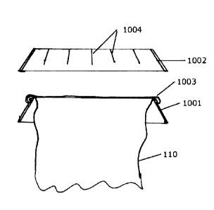
Figure 10 illustrates an embodiment of the glove 110 with a collar 111 which
is here formed
by an inner ring 1001 and an outer ring 1002. Both these rings are
approximately conical in
shape. The glove may be manufactured by stretching the edge 1003 of the glove
out over
the edge of the inner ring 1001 and then pressing or clicking the outer ring
1002 onto the
inner ring. The outer ring 1003 may optionally comprise a number of slits 1004
to increase its
flexibility and ability to be pressed onto the inner ring and the glove edge.
The geometry of an embodiment of the inner and outer rings are shown in figure
11A and
11B in a perspective and a side view, respectively. The diameter of the outer
ring may be
slightly larger than the diameter of the inner ring. The inner ring may
comprise a bent edge
1100 for the glove edge to be hold onto and stretched over.
In figure 12 is illustrated a system for mounting a container 101 according to
the invention.
The container as shown in figure 12B on either side comprises a groove 208 for
receiving the
CA 2986637 2017-11-24
84116238
14
legs 1201 of the bracket 1200 so that the container is held in place by the
bracket. The
bracket may then be fastened to e.g. a cleaning cart, a rack, a wall or the
like. The container
101 can then easily and quickly be released from the brackets for example to
be cleaned or
exchanged.
While preferred embodiments of the invention have been described, it should be
understood
that the invention is not so limited and modifications may be made without
departing from
the invention. The scope of the invention is defined by the appended claims,
and all devices
that come within the meaning of the claims, either literally or by
equivalence, are intended to
be embraced therein.
CA 2986637 2017-11-24