Note: Descriptions are shown in the official language in which they were submitted.
I
ATTACHABLE/DETACHABLE LAP BLANKETS FOR SEAT OCCUPANTS
FIELD OF THE INVENTION
The present invention relates generally to seating, and more particularly
to attachable/detachable seating accessories for increasing the comfort of
seat
occupants.
BACKGROUND
It is known to use blankets during seated participation in outdoor activities
to improve the comfort of a participant. For example, golf cart seat blankets
are known
that have slots for fitting over the armrests of a golf cart that resides at
opposite ends
of a multi-occupant bench-style seat of the golf cart. However, getting under
the blanket
requires that the user lift up the blanket from around the arm, making it
inconvenient to
repeatedly get in and out from under the blanket during play of game. Use of a
standard
blanket brought from home at various outdoor events is also problematic, as
the generic
blanket is not secured in any way to the seat, meaning that the blanket can
easily fall
to the floor and become soiled or lost, or even blow away if left momentarily
unattended
in a windy outdoor environment.
Accordingly, there remains room for improvement in the field of blanket.
aided seating comfort.
SUMMARY OF THE INVENTION
According to one aspect of the invention there is provided a lap blanket
system comprising:
a first set of one or more fastener elements supported or supportable on
a seat; and
a blanket having a second set of one or more fastener elements thereon,
said second set of one or more fastener elements being selectively matable
with at
CA 2986722 2017-11-27
2
least one of said first set of one or more fastener elements, whereby said
second set of
one or more fastener elements is operable to secure said blanket to said seat
through
the first set of one or more fastener elements.
According to a second aspect of the invention, there is provided a lap
warming method using the forgoing system, said method comprising selectively
switching the seat between a lap-warming configuration with the blanket
fastened to
the seat and a non-warming configuration with the blanket detached from said
seat
according to warming needs of a current or intended seat occupant.
According to a third aspect of the invention, there is provided a lap
warming method comprising selectively switching at least one occupant area of
a multi-
occupant seat between a lap-warming configuration and a non-warming
configuration
by selectively attaching or detaching a respective one of two blankets to said
occupant
area of the multi-occupant seat according to the needs of a current or
intended
occupant of said occupant area.
BRIEF DESCRIPTION OF THE DRAWINGS
Preferred embodiments of the invention will now be described in
conjunction with the accompanying drawings in which:
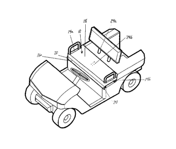
Figure 1 is a plan view of a golf cart blanket system according to one
embodiment of the present invention, which features a seat cover and two
attachable/detachable lap blankets.
Figure 2 is an exploded perspective view illustrating placement of the seat
cover of Figure 1 on a golf cart.
Figure 3 is a perspective view of the golf cart of Figure 2 after placement
of the seat cover thereon.
Figure 4 is a perspective view illustrating attachment of the lap blankets
CA 2986722 2017-11-27
3
of Figure 1 to the previously placed seat cover of Figure 3.
Figure 5 is a plan view of a portable seat and blanket system according
to another embodiment of the present invention.
In the drawings like characters of reference indicate corresponding parts
in the different figures.
DETAILED DESCRIPTION
Figure 1 illustrates a three-piece golf cart blanket system whose three
constituent pieces consist of a seat cover 10 and two lap blankets12a, 12b.
The seat
cover 10 is a fabric panel of sufficient area to fully cover a two-person seat
102 of a
conventional golf cart 100. In the illustrated embodiment, the seat cover has
a
rectangular shape of greater length in one direction than the other. The
longer of the
seat cover's two dimensions is referred to herein as its width dimension,
while the
shorter of the seat cover's two dimensions is referred to herein as its depth
dimension,
as the longer width dimension of the seat covers elongated shape lies spans
the
notable lateral width of the golf cart seat 102 when the seat cover is
installed, while the
shorter depth dimension of the seat cover spans the smaller front-to-rear
depth of the
golf cart seat 102. With this installed orientation in mind, the four-sided
perimeter of
the seat cover features elongated front and rear edges 10a, 10b that lie
parallel and
opposite to one another across the depth dimension of the cover when t laid
out flat,
and two shorter ends 10c, 10d that lie parallel and opposite to one another
across the
width dimension of the seat cover.
A short distance inward from each end 10c, 10d, the seat cover optionally
features a respective slot-shaped opening 14a, 14b that runs parallel to the
respective
end 10c, 10d thereof to fit over a respective handle 104a, 104b of the golf
cart 100 that
stands upright at a respective end of the golf cart seat 102. In the
illustrated
CA 2986722 2017-11-27
4
embodiment, the seat cover has a multi-layer construction, with a bottom
substrate
layer 16 of nylon or other fabric and an insulating top layer 18 of fleece,
wool or other
material of greater thermal insulative value than the substrate fabric. In the
illustrated
example, the insulating top layer 18 is slightly smaller than the bottom
substrate layer
16 in the depth direction of the seat cover, yet spans a substantial majority
of this depth
dimension, leaving only a relatively narrow strip 16a, 16b of the bottom
substrate layer
exposed along the front and rear edges 10a, 10b of the seat cover. These front
and
rear strips 16a, 16b of the seat cover 10 form overhanging portions thereof
that
overhang the front and rear edges of the golf cart seat 102 when the seat
cover is
.. installed thereon. Meanwhile, the insulating top layer 18 spans the entire
topside of the
golf cart seat 102 to provide a notable layer of thermal insulation thereon.
In other
embodiments, the insulating top layer 18 may span the entirety of the seat
cover.
As shown in the drawings, folded-over pockets may be provided at each
end of the front overhanging strip 16a of the seat cover to incorporate
weights therein,
thus providing weighted elements 20 at the front of the seat cover that help
hold the
seat cover down over the front edge of the golf cart seat 102. Such weights
are not
limited to placement at the front corners of the seat cover, as weights may
additionallh
or alternatively be incorporated elsewhere along the cover's front edge 10a,
for example
inside a folded-over hem at the front edge 10a. It will also be appreciated
that weights
may be attached to the cover by means other than a hem or other folded-over
enclosure. In the installed position of the seat cover 10, the rear strip 16b
of the seat
cover is preferably tucked behind or under the golf cart seat 102 at the rear
edge thereof
to also help hold the seat cover in place and resist lifting thereof by
blowing winds.
The two blankets 12a, 12b are defined by respective fabric panels of
equal size, which may be of single-layer or multi-layer construction and
preferably
CA 2986722 2017-11-27
5
include a thermally insulative material, for example the same fleece, wool or
other
insulative material used in the insulating top layer 18 of the seat cover 10.
A depth
dimension of each blanket is measured in the same direction as the depth
dimension
of the seat cover, but exceeds this depth dimension of the seat cover. A width
dimension of each blanket is measured in the same direction as the width
dimension of
the seat cover, and may be equal to or longer than the blanket's depth
dimension. The
width of each blanket is at least equal to, and preferably exceeds, half of
the seat
cover's width dimension, as each blanket 12a, 12b is intended to cover a
respective
half of the seat cover 10, thereby providing a respective lap blanket for each
occupant
of a two-occupant bench-style golf cart seat 102.
An imaginary mid-plane 22 lies parallel to the ends 10c, 10d of the seat
cover 10 at a central location therebetween to denote a widthwise center of
the seat
cover. This mid-plane 22 thus bisects the cover into two equally sized halves,
which
are of symmetrically mirrored relation to one another across this mid-plane
22. A first
set of fastener elements 24 is mounted to the insulating top layer 18 at the
topside of
the seat cover, and features a first subset of fastener elements 24a situated
in close
but spaced relation to the mid-plane 22 on a first side thereof, and a
matching second
subset of fastener elements 24b situated oppositely and symmetrically of the
first
subset in close but spaced relation to the mid-plane 22 on the opposing second
side
thereof. Each subset of fastener elements 24a, 24b thus resides on a
respective half
of the seat cover 10. Each subset 24a, 24b features a row of fastener elements
laid
out parallel to the mid-plane 22 in slightly spaced relation from one another
in the depth
direction of the seat cover.
First blanket 12a features a second set of fastener elements 26a thereon
that are laid out on the underside thereof in matching pattern and quantity to
the first
CA 2986722 2017-11-27
6
subset 24a of fastener elements on the topside of the seat cover 10. The
second set
of fastener elements 26a are thus laid out in a linear row whose spacing is
equal to that
found in the first subset 24a of fastener elements on the seat cover 10. The
rectangular
perimeter of the first blanket 12a features a front edge 28a, an opposing and
parallel
rear edge 28b, an outer edge 28c and an opposing and parallel inner edge 28d.
The
row of second fastener elements 26a on the first blanket 12a lies near and
parallel to
the inner edge 28d, at a distance therefrom equal to the distance measured
from the
mid-plane 22 of the seat cover 10 to the seat cover's first subset 24a of
fastener
elements. The second set of fastener elements 26a on the first blanket are of
a
corresponding and matable type to the first subset 24a of fastener elements on
the seat
cover 10, whereby the first blanket 12a is selectively attachable to the seat
cover 10 by
mating of the first blanket's fastener elements 26a with the seat cover's
first subset of
fastener elements 24a.
The second blanket 12b is of symmetrically mirrored relation to the first
blanket. Second blanket 12b features a third set of fastener elements 26b
therein that
is laid out on the underside thereof in matching pattern and quantity to the
second
subset 24b of fastener elements on the topside of the seat cover. The third
set of
fastener elements 26b are thus laid out in a linear row whose spacing is equal
to that
found in the second subset 24b of fastener elements on the seat cover 10. The
rectangular perimeter of the second blanket 12b features a front edge 30a, an
opposing
and parallel rear edge 30b, an outer edge 30c and an opposing and parallel
inner edge
30d. The row of second fastener elements 26b on the second blanket 12b lies
near
and parallel to the inner edge 30d at a distance therefrom that is equal to
the distance
measured from the mid-plane 22 of the seat cover 10 to the seat cover's second
subset
24b of fastener elements. The third set of fastener elements 26b on the second
blanket
CA 2986722 2017-11-27
7
are of a corresponding and matable type to the second subset 24b of fastener
elements
on the seat cover 10, whereby the second blanket 12b is selectively attachable
to the
seat cover 10 by mating of the second blanket's fastener elements 26b with the
seat
cover's second subset of fastener elements 24b.
The schematically illustrated fastener elements in the illustrated
embodiment are male and female snap fasteners, for example male snap fastener
elements 24a, 24b on the topside of the seat cover 10 and mating female snap
fastener
elements 26a, 26b on the underside of the blankets 12a, 12b. However, the
distribution
of male or female elements among the seat cover and blankets may be reversed,
or
other fastener types, e.g. hook and loop fastener elements, may be employed.
With reference to Figures 2 and 3, the seat cover 10 is first installed on
the seat 102 of the golf cart 100 by lowering the seat cover overtop of the
golf cart seat
102, which may involve slipping the slots 14a, 14b over the handles 104 of the
golf cart
100 if the seat cover is provided with such handle slots near the ends
thereof. The rear
strip 16b of the seat cover is tucked behind, and optionally under the golf
cart seat 102,
and the front strip 16a of the seat cover overhangs the front of the golf cart
seat to drape
downwardly therefrom. In this installed position of the seat cover, each half
thereof
covers a respective half of the two-occupant bench-style golf cart seat 102,
and the two
subsets 24a, 24b of fastener elements on the topside of the seat cover 10
reside atop
the golf cart seat 102 at a central area thereof that resides between the two
passengers
of the golf cart when the seat 102 is occupied.
Turning to Figure 4, should either passenger of the golf cart wish to have
a blanket available to them for warmth and/or comfort, for example depending
on
variable weather conditions, a respective one of the two blankets 12a, 12b is
detachably
fastened to the installed seat cover 10 by mating of the respective second or
third set
CA 2986722 2017-11-27
8
of fastener elements 26a, 26b on the blanket with the respective subset of
fastener
elements 24a, 24b on that passenger's respective half of the seat cover. The
mated
fastener elements hold the blanket to the seat cover, which in turn is secured
to the golf
cart seat. The blanket thus is thus secured to the golf cart seat, and will
not blow away,
or fall from cart onto the ground as the passenger boards and departs the golf
cart
between golf shots. At the same time, access to and from the cover of the
blanket is
quick and convenient, as the blanket is attached to the golf cart only at the
inner edge
of the blanket near the widthwise center of the golf cart. The front, rear and
outer edges
of the blanket remain freely movable relative to the seat cover 10 and
underlying seat
102, whereby the passenger can easily lift up the blanket by any of these free
edges to
slip their lap into and out of the confines of the blanket as they board the
golf cart each
time. Meanwhile, should either passenger of the cart not require a blanket,
their blanket
can be stored separately of the seat 102 in a detached state from the seat
cover, for
example in a storage compartment or golf bag elsewhere on the cart 100. The
seat
cover can be left in place for all users, regardless of blanket use, thus
providing an easy
way to equip the cart for selective blanket-attachment without factory
incorporation or
aftermarket installation of fastener elements directly to the seat upholstery.
This way,
the cover and attached fastener elements can be removed at any time, for
example for
washing or repair, or for hotter summer conditions in which blanket use is not
expected.
While the forgoing embodiment is presented in the context of a multi-
blanket system for a multi-occupant bench-like seat on a golf cart, it will be
appreciated
that similar application of a smaller seat cover with a single
attachable/detachable
blanket may be used a single-occupant seat. Additionally, though the forgoing
embodiment features fastener elements mounted on a fabric seat cover for
indirect
support on the seat over which the cover is installed, mounting of the first
set of fastener
CA 2986722 2017-11-27
9
elements directly to the seat itself is also contemplated. While the
illustrated
embodiment employs multiple fasteners laid out in a row on each blanket and
each half
of the seat cover, as few as one fastener at each of these fastening locations
may be
sufficient. Also, while the first illustrated embodiment focuses on a golf
cart, use on
other vehicles is also contemplated, whether on other open-air vehicles where
the
passengers are exposed to the surrounding environment, or vehicles with
enclosed
passenger cabins. Additionally, the lap blanket system is not limited to
vehicular
applications, and may be used in stationary seating contexts, including both
indoor and
outdoor venues, such as stadiums, arenas, theatres, tents, music halls,
churches, etc.
Figure 5 shows a portable seat and blanket system according to a second
embodiment, which is particularly useful in scenarios where no padded seating
surfaces
are readily available. The system once again features first and second
blankets 12a,
12b of the same type described above for the golf cart embodiment, but the
first and
second subsets 24a, 24h of fastener elements are mounted on respective
detachable
halves of a cushioned portable seat 50 rather than on respective halves of a
non-
cushioned fabric seat cover used on an already-padded golf cart seat. When
attached
together, the two halves 50a, 50b of the portable seat 50 are symmetrically
mirrored
across a mid-plane 22 that resides centrally between ends of the portable
seat, just like
the two halves of the first embodiment's seat cover.
Each half 50a, 50b of the portable seat 50 features a fabric shell 48 inside
of which compressible materials (e.g. resiliently compressible foam) is
contained. The
shells may be made of, or externally lined with, wool, fleece or other
thermally insulative
material. When assembled, the overall seat 10' is of elongated rectangular
shape like
that of the seat cover of the first embodiment. Each rectangular half of the
overall seat
has a front edge 52a, a rear edge 52b, an outer edge 52c and an inner edge
52d. The
CA 2986722 2017-11-27
10
inner edges 52d of the two halves resides adjacent one another, while the
outer edges
lie opposite one another to define the opposing ends of the portable seat 50
between
which the mid-plane 22 is centered in the widthwise direction. The inner edges
52d of
the two halves feature mating zipper teeth in order to cooperably define a
zipper 54 that
is located at the mid-plane 22. Using this zipper 54, the two halves are
selectively
attachable and detachable to and from one another. A respective handle loop 56
is
attached to each half 50a, 50b of the portable seat 50 at or near the outer
edge 52c
thereof so that the handle loop 56 reaches outwardly beyond the outer edge
52c.
The row of fastener elements in each subset 24a, 24b on the portable
seat 50 resides near and parallel to the zipper 54 at the mid-plane of the
seat, and the
two blankets 12a, 12b are selectively attachable to the respective halves 50a,
50b of
the portable cushion in the same manner that the blankets attach to the seat
cover in
the first embodiment. In a known manner, the zipper teeth are attached to the
shells of
the seat halves by respective flaps of fabric, whereby when the halves of the
seat are
attached together by the zipper 54, they are also pivotal relative to one
another about
the axis of the zipper due to flexibility in these zipper attachment flaps.
About this pivot
axis, the halves of the seat can be folded together into face-to-face relation
to one
another, thus bringing together the two outer edges 52c of the seat and the
two handle
loops 56 supported at these outer edges. This reduces the footprint of the
portable seat
into a compact form for efficient transport and store, while the handle loops
provide
convenient and comfortable carrying of the folded unit in one hand.
The seat and the selectively attachable/detachable blankets can be used
in two different modes: a shared multi-occupant mode, or a divided individual
mode. In
the shared multi-occupant mode, the two halves 50a, 50b of the seat are left
zipped
together, and are unfolded away from one another so as to lie in coplanar side-
by-side
CA 2986722 2017-11-27
11
relation, as shown in Figure 5, rather than in adjacent face-to-face relation
like in the
folded-up transport position. The zipped-together coplanar halves are laid
down atop
a bench, ground area or other generally horizontal surface capable of
supporting
multiple occupants, and two users each then sit atop a respective half of the
assembled
portable seat. Each user has the option of whether to attach the respective
blanket to
their half of the multi-occupant portable seat. In the divided individual
mode, the zipper
54 is undone in order to separate the two halves of the portable seat from one
another
for use of each as an individual seat by a respective user. This is useful in
contexts
where a large enough surface for seating of multiple users side-by-side is
unavailable
(e.g. stadiums, arenas or other venues with individual seating, as opposed to
bench
seating), or where the two individuals attending an event and intending to
share the
same portable seat 50 are unable to obtain seating spaces directly beside one
another.
In addition to the heat retaining, wind-shielding function of the blanket to
help protect a user against cold environmental conditions, the portable seat
may
additionally incorporate other cold-combatting features, for example
incorporating one
or more heating elements into its construction. While the illustrated
embodiment uses
a zipper to attach and detach to the halves of the portable seat to and from
one another,
other embodiments may employ other fastener types, for example the same or
similar
snap fasteners as those used to selectively attach and detach the blankets, or
hook
and look fasteners. In any case, elements of matable type are mounted on the
two
sections at their inner edges thereof (e.g. mating zipper teeth, mating male
and female
snap components, mating pieces of hook and loop fabric, etc.) for cooperation
with one
another to selective attach the two halves together, with the elements on at
least one
half preferably mounted on a flexible fabric flap to allow pivotal folding of
the two halves
relative to one another. The term "attachment elements" is used herein to
denote these
CA 2986722 2017-11-27
12
fastener components by which the halves of the portable seat are attachable to
one
another, while distinguishing same from the "fastener elements" used to
selectively
attach the blankets.
While the forgoing embodiment describes a two-user portable seat with
two equally sized sections each representing a respective "half' of the
portable seat, it
will be appreciated that other multi-occupant portable seats may employ a
different
quantity and/or different relative sizing of multiple zipped-together or
otherwise
attachable/detachable sections each denoting a respective seating area for a
single
occupant and each possessing a respective subset of fasteners thereon for
optional
connection of a respective individual user's blanket. Also, while the
illustrated
embodiments place the subset of fastening elements near the center of the seat
cover
or portable seat, which is advantageous in the golf cart embodiment so that
the blanket
is swung inwardly of the vehicle when lifted off the wearer's lap, it will be
appreciated
that the fastener elements may alternatively be placed at other areas of a
seat cover or
portable seat while still gaining other benefits of use.
Since various modifications can be made in my invention as herein above
described, and many apparently widely different embodiments of same made, it
is
intended that all matter contained in the accompanying specification shall be
interpreted
as illustrative only and not in a limiting sense.
CA 2986722 2017-11-27