Note: Descriptions are shown in the official language in which they were submitted.
CA 02986752 2017-11-21
WO 2016/191393 PCT/US2016/033835
JOINT OR SEGMENTAL BONE IMPLANT FOR DEFORMITY CORRECTION
Cross-Reference
[0001] This application is related to United States provisional application
number
62/165,376, filed May 22, 2015, entitled "JOINT OR SEGMENTAL BONE IMPLANT FOR
DEFORMITY CORRECTION", naming Samuel Adams as the inventor. The contents of
the
provisional application are incorporated herein by reference in their
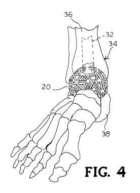
entirety, and the benefit
of the filing date of the provisional application is hereby claimed for all
purposes that are
legally served by such claim for the benefit of the filing date.
Background
[0002] A medical implant is described and, more particularly, a medical
implant for use in
joint or segmental bone defects for deformity correction with or without
obtaining
arthrodesis.
[0003] Implants may be used in humans or animals to support or secure one
or more
bones. Once implanted, the implant may provide support between the bones and
bone growth
may take place around and through the implant to at least partially fuse the
bones for long-
term support.
[0004] There is a need for an improved medical implant for use in body
areas, such as
bones of the foot and ankle.
Summary
[0005] An implant is provided for use in an ankle joint between
reconditioned end
surfaces established on a distal end of an upper tibia bone and an opposing
lower talus bone.
The implant comprises a substantially porous rigid component adapted to be
anchored against
the upper tibia reconditioned end surface and the lower talus reconditioned
end surface. The
component defining an opening therethrough. An intramedullary nail is
configured to pass
through the opening in the component when the nail is driven through the talus
and into the
tibia.
[0006] A method of securing an ankle joint is also provided. The method
comprises the
steps of reconditioning end surfaces on a distal end of an upper tibia bone
and an opposing
1
CA 02986752 2017-11-21
WO 2016/191393 PCT/US2016/033835
lower talus bone of the ankle joint. A substantially porous rigid component is
positioned
against the upper tibia reconditioned end surface and the lower talus
reconditioned end
surface. The component defining an opening therethrough. An intramedullary
nail
configured to be driven through the through the talus and the opening in the
component and
into the tibia.
Brief Description Of The Drawings
[0007] For a more complete understanding of the bone implant, reference
should now be
had to the embodiments shown in the accompanying drawings and described below.
In the
drawings:
[0008] FIG. 1 is a top plan view of an embodiment of a joint or segmental
bone implant.
[0009] FIG. 2 is a top perspective view of the bone implant as shown in
FIG. 1.
[0010] FIG. 3 is a perspective view of the bone implant as shown in FIG. 1
receiving a
portion of an intramedullary nail.
[0011] FIG. 4 is a perspective view of the bone implant as shown in FIG. 1
positioned in a
foot and ankle joint.
[0012] FIG. 5 is an exploded perspective view of the bone implant and the
foot and ankle
joint as shown in FIG. 4.
[0013] FIG. 6A is a side elevation view of the bone implant as shown in
FIG. 1 positioned
in a foot and ankle joint.
[0014] FIG. 6B is an opposite side elevation view of the bone implant
positioned in a foot
and ankle joint as shown in FIG. 6A.
[0015] FIG. 6C is a rear perspective view of the bone implant positioned in
a foot and
ankle joint as shown in FIG. 6A.
[0016] FIG. 6D is a front perspective view of the bone implant shown in
phantom
positioned in a foot and ankle joint as shown in FIG. 6A.
2
CA 02986752 2017-11-21
WO 2016/191393 PCT/US2016/033835
[0017] FIG. 6E is a top perspective view of the bone implant positioned in
a foot and
ankle joint as shown in FIG. 6A.
[0018] FIG. 7A is a side elevation view of the bone implant as shown in
FIG. 1 positioned
in a foot and ankle joint and a portion of an intramedullary nail shown in
phantom.
[0019] FIG. 7B is a rear perspective view of the bone implant positioned in
a foot and
ankle joint as shown in FIG. 7A.
[0020] FIG. 7C is an opposite side elevation view of the bone implant
positioned in a foot
and ankle joint as shown in FIG. 7A.
[0021] FIG. 7D is a top plan view of the bone implant positioned in a foot
and ankle joint
as shown in FIG. 7A.
[0022] FIG. 7E is an up-close view of the bone implant positioned in a foot
and ankle joint
as shown in FIG. 7A.
[0023] FIG. 8 is a perspective view of another embodiment of a bone implant
positioned
in a foot and ankle joint and including a fixation device.
[0024] FIG. 9 is an elevation view of a third embodiment of a bone implant
having a
planar surface to accommodate a plate or other device.
[0025] FIG. 10 is an elevation view of a fourth embodiment of a bone
implant positioned
in a foot and ankle joint.
[0026] FIG. 11 is a perspective view of fifth embodiment of a bone implant
for use in a
foot and ankle joint.
[0027] FIG. 12 is a perspective view of a sixth embodiment of a bone
implant for use in a
foot and ankle joint.
[0028] FIG. 13 is schematic elevation view of the third embodiment of the
bone implant
as shown in FIG. 9 between two portions of bone.
[0029] FIG. 14 is schematic elevation view of a seventh embodiment of a
bone implant
shown between two portions of bone.
3
CA 02986752 2017-11-21
WO 2016/191393 PCT/US2016/033835
Description
[0030] Certain terminology is used herein for convenience only and is not
to be taken as a
limitation on the invention. For example, words such as "upper," "lower,"
"left," "right,"
"horizontal," "vertical," "upward," and "downward" merely describe the
configuration shown
in the FIGs. Indeed, the components may be oriented in any direction and the
terminology,
therefore, should be understood as encompassing such variations unless
specified otherwise.
[0031] Referring now to FIGs. 1 and 2, there is shown an embodiment of a
medical joint
or segmental bone implant for deformity correction and generally designated at
20. The
implant 20 comprises a porous web structure 22 configured to interface with
human bone
tissue. The web structure 22 extends throughout the implant 20 to provide
support. The web
structure 22 disperses the stress of compressive forces throughout implant 20,
wherein the
implant 20 is supported against tensile, compressive, and shear forces. The
web structure 22
can be further employed to receive and distribute throughout the implant 20
loading forces of
the surrounding tissue. The web structure 22 may also reinforce the implant 20
along
multiple planes.
[0032] In one embodiment, the web structure 22 is formed with
interconnected triangular-
shaped building blocks. The result is a web structure 22 formed from a pattern
of
triangularly-shaped geometrical building blocks. The triangularly-shaped
building blocks
may form tetrahedrons that may also be used as building blocks. Other patterns
from the
triangles are also contemplated. Each tetrahedron may include four triangular
faces in which
three of the four triangles meet at each vertex. At least two of the plurality
of tetrahedrons
are coupled together via one or more common components connecting two
respective vertices
on each of the two tetrahedrons such that two tetrahedrons share a common unit
to form a
hexahedron.
[0033] In one embodiment, the porous web structure 22 is configured to form
a
substantially spherical structure as shown in FIGs. 1 and 2. The implant 20
can have a
diameter of at least about 38 mm to about 40 mm. However, it is understood
that the design
of the implant 20 may be sized appropriately to meet specified dimensions of
the
implantation site. In some embodiments, multiple implants of different sizes
may be
constructed and delivered in a kit. A medical health professional may choose
an implant
(e.g., according to a needed size) during surgery. It is understood that while
the embodiment
4
CA 02986752 2017-11-21
WO 2016/191393 PCT/US2016/033835
of the implant 20 has been described with respect to a particular spherically-
shaped web
structure, various shapes of web structures are contemplated. For example, a
portion of the
spherical implant may be removed to form an implant 44 having a planar side
(FIG. 9). In
another embodiment shown in FIG. 14, the implant 54 may be egg-shaped (FIG.
14).
[0034] The implant 20 may be formed from a biocompatible material such as a
titanium
alloy (e.g., y-titanium aluminides), cobalt, chromium, stainless steel,
polyetheretherketone
(PEEK), ceramics, or other suitable material. The implant 20 may be made
through a rapid
prototyping process (e.g., electron beam melting (EBM) process). Other
processes are also
possible, such as injection molding, casting, sintering, selective laser
sintering (SLS), direct
metal laser sintering (DMLS), etc). SLS may include laser-sintering of high-
performance
polymers such as that provided by EOS of North America, Inc., headquartered in
Novi,
Michigan, U.S.A. High-performance polymers may include various forms of PEEK
(e.g.,
HP3 having a tensile strength of up to about 95 mega Pascal (MPa) and a
Young's modulus of
up to about 4400 MPa and continuous operating temperature between about 180 C
(356 F)
and 260 C (500 F)). Other materials may include PA 12 and PA 11 provided by
EOS of
North America, Inc. Multiple parts may be cast or injection molded and joined
together (e.g.,
through welding, melting, etc.). For example, individual components 24 forming
the implant
20 may be generated separately (e.g., by casting, injection molding, etc.) and
welded together
to form the implant 20. The porous web structure 22 may be made according to
the
disclosure of International Application No. PCT/U52012/045717, filed July 6,
2012, and
published January 10, 2013, as International Publication No. WO 2013/006778,
the contents
of which are hereby incorporated by reference in their entirety.
[0035] In another embodiment shown in FIG. 12 and generally designated at
50, the web
structure 22 of the implant 50 may be formed from a generally porous material
having
random openings 45.
[0036] The implant 20, 50 may include a top face 26 and an opposed bottom
face 28
wherein at least a portion of the top face 26 and the bottom face 28 are
generally parallel to
one another. In use, the top and bottom faces 26, 28 are configured to be
disposed in contact,
or near contact, of an adjacent bony structure for contacting the bony
structure during use to
adhere or couple with the adjacent structure when implanted. As depicted, for
example, the
implant 20, 50 is intended to sandwich between two adjacent bony structures
interfacing with
bone structure of a foot and ankle joint 34. The top contact face 26 may
couple to a portion
CA 02986752 2017-11-21
WO 2016/191393 PCT/US2016/033835
of the first bony structure disposed above implant 20 and the bottom contact
face 28 may
couple to the second bony structure disposed below implant 20.
[0037] The web structure 22 defines openings configured to define open
volume to enable
bone growth through the openings of the web structure 22, thereby enhancing
coupling of the
implant 20 to the adjacent bony structure. At least a portion of the web
structure 22 is in
contact, or near contact, with the adjacent bony structure, thereby enabling
bone growth to
extend into or through at least a portion of open volume of the web structure
22 such that the
bone growth interlocks with the web structure 22 of the implant 20. The
interlocking of the
bone growth and the web structure 22 may rigidly fix the implant 20 in a fixed
location
relative to the bony structure. For example, a web structure 22 may define an
open space for
bone growth therethrough, thereby enabling bone through growth to interlock
the bone
structure and the web structure 22 with one another to couple the implant 20
to the bony
structure at or near the contact surface. Such interlocking bone through
growth may inhibit
movement between the implant 20 and the bony structure, which could otherwise
lead to
loosening, migration, subsidence, or dislodging of the implant 20 from the
intended position.
[0038] The web structure 22 of the implant 20 may also provide surface area
for bone
graft fusion. For example, the voids in the web structure 22 of the implant 20
may be filled
with, or surfaces of the web structure 22 may be coated with, bone grafting
material, a
biologic, growth factor or the like. The web structure 22 extending throughout
the implant 20
may add additional surface area on the surface of the components 24 to fuse to
the bone graft
material and prevent the bone graft material from loosening or migrating from
the implant 20.
In some embodiments, the web structure 22 may also support and facilitate bone
in-growth.
For example, adjacent bone in an ankle joint may grow over at least a portion
of the
components 24 of the implant 22. The bone growth and engagement between the
bone
growth and the implant 20 may further stabilize the implant. In some
embodiments, the
surfaces of the implant 20 may be formed with a rough surface to assist in
bone in-growth
adhesion.
[0039] At least a portion of the open volume of the web structure 22 of the
implant 20
may be filled with bone growth material. For example, cancellous bone may be
packed into
the openings internally of the implant 20. In some embodiments, at least a
portion of the
surfaces of implant 20 may be coated or treated with a material intend to
promote bone
growth or bone adhesion or an antimicrobial agent to prevent infections. For
example, in
6
CA 02986752 2017-11-21
WO 2016/191393 PCT/US2016/033835
some embodiments, the surface of the web structure 22 may be coated with a
biologic or a
bone growth factor. For example, the biologic or growth factor may be
physically secured to
the web structure 22 in a central portion of the implant 20 provided there is
the physical
attachment of the biologic or growth factor. The biologic may include a
coating, such as
hydroxyapatite, bone morphaginic protein (BMP), insulin-like growth factors I
and II,
transforming growth factor-beta, acidic and basic fibroblast growth factor,
platelet-derived
growth factor, or similar bone growth stimulant that facilitates good
biological fixation
between the bone growth and a surface of the implant 20. The bone growth
factor may
include a naturally occurring substance capable of stimulating cellular
growth, proliferation
and cellular differentiation (e.g., a protein or steroid hormone).
[0040] As shown in the FIGs. 1 and 2, the center portion of the spherical
web structure 22
defines a cylindrical passage 30. The central passage 30 is configured to
receive an
intramedullary nail extending therethrough (FIG. 3).
[0041] In the embodiment of the implant 44 shown in FIG. 9, the planar or
aspherical
portion of the implant 44 accommodates a plate 42 or the like to facilitate
attaching the
combined porous web structure 45 and the plate 42 to bone using screws 48. For
example,
where an implant is implanted adjacent to a bony structure, one or more
structures may be
disposed on or extend from a surface (e.g., an interface plate) of the implant
that is intended
to contact, and at least partially adhere to, the bony structure during use.
[0042] A method is provided that includes the steps of providing an opening
in a foot or
ankle 34 of a human, and installing into the opening the implant 20, 44, 50,
54. The implant
location is first prepared, including surgical dissection for forming an
opening proximate the
foot or ankle 34 to the level of proposed implantation. Next, a bone bed can
be prepared
from the adjacent bony structure either by using a spherical reaming device or
using a saw
and osteotomes. The bone bed may be formed in either a joint or within a
single bone. Bone
graft material may be packed in the bone bed or within the porous web
structure 22 of the
implant 20. The implant 20 is then inserted into the bone bed. The implant 20
may be
incorporated into the end surfaces established between an upper tibia bone 36
and an opposite
and lower talus bone 38. The shape of at least a portion of the implant 20
allows the bone or
the joint surface on either side of the implant 20 to be placed in a preferred
position, for
example, to correct a deformity. FIGs. 6A-6E show the implant 20 disposed in
respective
openings of the foot and ankle bones.
7
CA 02986752 2017-11-21
WO 2016/191393 PCT/US2016/033835
[0043] In some embodiments, inserting the implant 20 includes positioning
the implant 20
adjacent the boney structure, aligning the web structure 22 with a
complementary portion of
the boney structure, or advancing a contact surface toward the boney structure
such that at
least the web structure 22 is in contact or near contact with the boney
structure. In some
embodiments, the implant 20 may be advanced until the contact surface is in
contact or near
contact with the boney structure, such that at least portion or substantially
all of the web
structure 22 is disposed in the boney structure.
[0044] The implant 20 then may, or may not be, fixed in place. In one
embodiment, an
intramedullary nail 32 is inserted into the heel and through the passage 30 in
the web
structure 22 of the implant 20. The nail 32 is driven into the end of the
tibia 36 for fusing the
foot and ankle joint 34 (FIGs. 7A-7E). In an embodiment shown in FIG. 8, a tab
40 integral
with the web structure 22 may be included on the implant 20. The tab 40 may be
secured to
adjacent bone with staples, screws, plates, or other means of fixation. FIG.
11 shows
openings in the intramedullary nail 32 for receiving at least one screw
passing through
another part of the foot and ankle joint.
[0045] FIGs. 13 and 14 schematically show the implants 44, 54 having an
aspherical side
and an egg-shape implant contacting adjacent bony structure 56. As depicted,
the implants
44, 54 are intended to be disposed between the adjacent bony structures
interfacing with bone
structure of a foot and ankle joint. The top of the implants 44, 54 may couple
to a portion of
the first bony structure 56 disposed above the implants and the bottom contact
faces 28 may
couple to the second bony structure disposed below implants 44, 54.
[0046] Once the implant is positioned in the foot and ankle joint 34, the
access point to the
implant site may be closed using sutures or other closure devices.
[0047] Although the bone implant has been shown and described in
considerable detail
with respect to only a few exemplary embodiments thereof, it should be
understood by those
skilled in the art that I do not intend to limit the invention to the
embodiments since various
modifications, omissions and additions may be made to the disclosed
embodiments without
materially departing from the novel teachings and advantages, particularly in
light of the
foregoing teachings. Accordingly, I intend to cover all such modifications,
omission,
additions and equivalents as may be included within the spirit and scope of
the bone implant
as defined by the following claims. In the claims, means-plus-function clauses
are intended
8
CA 02986752 2017-11-21
WO 2016/191393
PCT/US2016/033835
to cover the structures described herein as performing the recited function
and not only
structural equivalents but also equivalent structures. Thus, although a nail
and a screw may
not be structural equivalents in that a nail employs a cylindrical surface to
secure wooden
parts together, whereas a screw employs a helical surface, in the environment
of fastening
wooden parts, a nail and a screw may be equivalent structures.
9