Note: Descriptions are shown in the official language in which they were submitted.
CA 02987040 2017-11-23
WO 2016/191324 PCT/US2016/033674
TRANSCATHETER PULMONARY BALL VALVE ASSEMBLY
Inventor: Min Frank Zeng and Pham Lo
BACKGROUND OF THE INVENTION
1. Field of the Invention
The present invention is directed to methods, systems, and apparatus for
transcatheter placement of a pulmonary valve to restore pulmonary valve
function in
a patient.
2. Description of the Prior Art
Patients with congenital heart defects involving the right ventricular outflow
tract (RVOT), such as Tetralogy of Fallot, Truncus Arteriosus, and
Transposition of
the Great Arteries, are commonly treated by surgical placement of an RVOT
conduit
between the right ventricle (RV) and pulmonary artery (PA). However, despite
advances in terms of durability, the lifespan of RVOT conduits is relatively
limited,
and most patients with congenital RVOT defects are committed to multiple
cardiac
surgeries over their lifetime.
Common failure modes for conduits include calcification, intimal
proliferation,
and graft degeneration. which result in stenosis and regurgitation, alone or
in
combination. Both stenosis and regurgitation place an increased hemodynamic
burden on the right ventricle. and can result in reduced cardiac function.
Percutaneous placement of stents within the conduit can provide palliative
relief of
stenosis, and may eliminate or postpone the need for surgery. However, stent
placement is only useful to treat conduit stenosis. Patients with predominant
regurgitation or mixed stenosis and regurgitation cannot be adequately treated
with
stents.
Although pulmonary regurgitation is generally well tolerated for many years
when the pulmonary vasculature is normal, long-term follow-up has revealed its
detrimental effect on right and left ventricular function. Chronic volume
overload of
the RV leads to ventricular dilatation and impairment of systolic and
diastolic
function, which in the long term leads to reduced exercise tolerance,
arrhythmias,
and an increased risk of sudden death. Restoration of pulmonary valve
competence
at an appropriate time has resulted in improvement of right ventricular
function,
incidence of arrhythmias, and effort tolerance. However, if RV dilation
progresses
CA 02987040 2017-11-23
WO 2016/191324 PCT/US2016/033674
beyond a certain point, reportedly to an RV end-diastolic volume on the order
of 150-
170 mL/m2, normalization of RV size may not be possible, even with pulmonary
valve
placement. This finding suggests that the benefits of restoring pulmonary
valve
competence may be greatest when the RV retains the capacity to remodel, and
that
earlier pulmonary valve replacement may be optimal.
Until recently, the only means of restoring pulmonary valve competence in
patients with a regurgitant conduit has been surgical valve or conduit
replacement.
Although this treatment is generally effective in the short-term, with low
mortality,
open heart surgery inevitably entails risks, including the acute risks of
cardiopulmonary bypass, infection, bleeding. and postoperative pain, as well
as the
chronic impact on the myocardium and brain. Furthermore, adolescents and
adults
are reluctant to undergo reoperation where the longevity of the new conduit
does not
guarantee freedom from future operations. Thus, a less invasive treatment for
conduit dysfunction would be welcomed by patients and their families, and may
allow
safe, earlier intervention for conduit dysfunction that mitigate the negative
effects of
chronic volume and pressure loading of the RV.
Thus, there remains a need for effective treatment congenital heart defects
involving the right ventricular outflow tract (RVOT).
SUMMARY OF THE DISCLOSURE
The present invention provides a pulmonary valve assembly and associated
delivery system that allows percutaneous transcatheter placement of a
biological
valve within a self-expanding stent at the RVOT for a patient. The pulmonary
valve
assembly restores pulmonary valve function in patients with a dysfunctional
RVOT
conduit and a clinical indication for pulmonary valve replacement. Unlike
currently
available options for pulmonary valve replacement, the pulmonary valve
assembly of
the present invention is intended to be placed inside a percutaneous
transcatheter
delivery system, and thus does not require implantation or deployment through
invasive surgical procedures.
The present invention provides a heart valve assembly comprising a frame
comprising an anchoring section, a generally cylindrical leaflet support
section, and a
neck section that transitions between the anchoring section and the valve
support
section. The anchoring section has a ball-shaped configuration defined by a
plurality
CA 02987040 2017-11-23
WO 2016/191324 PCT/US2016/033674
of wires that extend from the leaflet support section, with each wire
extending radially
outwardly to a vertex area where the diameter of the anchoring section is at
its
greatest, and then extending radially inwardly to a hub. A plurality of
leaflets are
stitched to the leaflet support section.
The present invention provides a method for securing the heart valve
assembly in the pulmonary trunk of a human heart. The heart valve assembly is
delivered to the location of a native pulmonary trunk, the vertex area of the
anchoring
section is deployed into the native pulmonary arteries such that the vertex
area is
retained in the pulmonary arteries, and then the leaflet support section is
deployed in
the pulmonary trunk.
BRIEF DESCRIPTION OF THE DRAWINGS
FIG. 1 is a perspective side view of a pulmonary valve assembly according to
one embodiment of the present invention shown in an expanded configuration.
FIG. 2 is a side view of the assembly of FIG. 1.
FIG. 3 is a top view of the assembly of FIG. 1.
FIG. 4 is a bottom view of the assembly of FIG. 1.
FIG. 5 is a perspective side view of the frame of the assembly of FIG. 1.
FIG. 6 is a side view of the frame of FIG. 5.
FIG. 7 is a top view of the frame of FIG. 5.
FIG. 8 is a bottom view of the frame of FIG. 5.
FIG. 9A is a perspective view of the leaflet assembly of the pulmonary valve
assembly of FIG. 1.
FIG. 9B is a side view of the leaflet assembly of FIG. 9A.
FIG. 10 illustrates a delivery system that can be used to deploy the assembly
of FIG. 1.
FIG. 11 illustrates a cross-section of a human heart.
FIGS. 12-16 illustrate how the assembly of FIG. 1 can be deployed in the
pulmonary trunk of a patient's heart using a transapical delivery system.
FIG. 17 illustrates the assembly of FIG. 1 deployed in the mitral position of
a
human heart.
CA 02987040 2017-11-23
WO 2016/191324 PCT/US2016/033674
DETAILED DESCRIPTION OF THE PREFERRED EMBODIMENTS
The following detailed description is of the best presently contemplated modes
of carrying out the invention. This description is not to be taken in a
limiting sense,
but is made merely for the purpose of illustrating general principles of
embodiments
of the invention. The scope of the invention is best defined by the appended
claims.
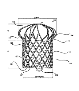
The present invention provides a pulmonary valve assembly 100 that is shown
in fully assembled form in FIGS. 1-4. The assembly 100 has a frame 101 (see
FIGS.
5-8) that has an anchoring section 109 and a leaflet support section 102 that
is
adapted to carry an integrated leaflet assembly that comprises a plurality of
leaflets
106. The assembly 100 can be effectively secured at the native pulmonary trunk
area. The overall construction of the assembly 100 is simple, and effective in
promoting proper mitral valve function.
As shown in FIGS. 5-8. the frame 101 has a ball-shaped anchoring section
109 that transitions to a leaflet support section 102 via a neck section 111.
The
different sections 102. 109 and 111 can be made of one continuous wire, and
can be
made from a thin wall biocompatible metallic element (such as stainless steel.
Co-Cr
based alloy. NítinOlTM, Ta. and Ti etc.). As an example, the wire can be made
from a
Nitinol TM wire that is well-known in the art, and have a diameter of 0.2" to
0.4".
These sections 109, 102 and 111 define open cells 103 within the frame 101.
Each
cell 103 can be defined by a plurality of struts 128 that encircle the cell
102. In
addition, the shapes and sizes of the cells 103 can vary between the different
sections 109, 102 and 111. For example, the cells 103 for the leaflet support
section
102 are shown as being diamond-shaped.
The leaflet support section 102 is generally cylindrical, functions to hold
and
support the leaflets 106, and has an inflow end that is configured with an
annular zig-
zag arrangement of inflow tips 107. The zig-zag arrangement defines peaks
(i.e., the
tips 107) and valleys (inflection points 129). In addition, ears 115 are
provided
opposite to each other at the inflow end, with each ear 115 formed by a curved
wire
portion connecting two adjacent tips 107. As shown in FIG. 1. the leaftlets
106 can
be sewn directly to the struts 128 of the cells 103 in the leaflet support
section 102.
The outflow end of the leaflet support section 102 transitions to the
anchoring
section 109 via a neck section 111 that also functions as an outflow end for
the
leaflet support section 102. The anchoring section 109 functions to secure or
anchor
the assembly 100, and specifically the frame 101, to the pulmonary trunk of
the
CA 02987040 2017-11-23
WO 2016/191324 PCT/US2016/033674
human heart. The anchoring section 109 has a ball-shaped configuration defined
by
a plurality of wires 113 that extend from a cell 103 in the leaflet support
section 102,
with each wire 113 extending radially outwardly to a vertex area 104 where the
diameter of the anchoring section 109 is at its greatest, and then extending
radially
inwardly to a hub 105. As best shown in FIG. 7, adjacent pairs of wires 113
converge towards a connection point at their upper ends before the connection
point
merges into the hub 105. This arrangement results in the anchoring section 109
have alternating large cells 103a and smaller cells 103b. See FIG. 6.
All portions of the anchoring section 109 have a wider diameter than any
portion of the leaflet support section 102 or the neck section 111.
The following are some exemplary and non-limiting dimensions for the frame
101. For example, referring to FIGS. 2 and 6, the height H1 of the leaflet
support
section 102 can be between 25-30mm: the height H2 of the anchoring section 109
can be between 7-12mm: the diameter Dball of the anchoring section 109 at the
vertex area 104 can be between 40-50mm; and the diameter DVALVE of the leaflet
support section 102 can be between 24-34mm.
In addition, the length of the leaflet support section 102 can vary depending
on the number of leaflets 106 supported therein. For example, in the
embodiment
illustrated in FIGS. 1-4 where three leaflets 106 are provided, the length of
the leaflet
support section 102 can be about 10-15mm. If four leaflets 106 are provided.
the
length of the leaflet support section 102 can be shorter, such as 8-10mm.
These
exemplary dimensions can be used for an assembly 100 that is adapted for use
at
the native pulmonary tract for a generic adult.
Referring now to FIGS. 1-4 and 9A-9B, the leaflet assembly is made up of a
tubular skirt 122, a top skirt 120, and a bottom skirt 121, with a plurality
of leaflets
sewn or otherwise attached to the tubular skirt 122 inside the channel defined
by the
tubular skirt 122. The tubular skirt 122 can be stitched or sewn to the struts
128. A
separate ball skirt 125 can be sewn or stitched to the hub 105. The leaflets
106 and
the skirts 120, 121, 122 and 125 can be made of the same material. For
example,
the material can be a treated animal tissue such as pericardium, or from
biocompatible polymer material (such as PTFE. Dacron. bovine. porcine, etc.).
The
leaflets 106 and the skirts 120, 121, 122 and 125 can also be provided with a
drug or
bioagent coating to improve performance, prevent thrombus formation. and
promote
CA 02987040 2017-11-23
WO 2016/191324 PCT/US2016/033674
endothelialization, and can also be treated (or be provided) with a surface
layer/coating to prevent calcification.
The assembly 100 of the present invention can be compacted into a low
profile and loaded onto a delivery system, and then delivered to the target
location by
a non-invasive medical procedure, such as through the use of a delivery
catheter
through transapical, or transfemoral, or transseptal procedures. The assembly
100
can be released from the delivery system once it reaches the target implant
site, and
can expand to its normal (expanded) profile either by inflation of a balloon
(for a
balloon expandable frame 101) or by elastic energy stored in the frame 101
(for a
device where the frame 101 is made of a self-expandable material).
FIGS. 12-16 illustrate how the assembly 100 can be deployed at the
pulmonary trunk of a patient's heart using a transapical delivery. FIG. 11
illustrates
the various anatomical parts of a human heart, including the pulmonary trunk
10, the
left pulmonary artery 12, the junction 11 of the pulmonary arteries, the
pulmonary
valve 13, the topwall pulmonary artery 17, the right atrium 14. the right
ventricle 15,
the tricuspid valve 20. the left ventricle 21, and the left atrium 22.
Referring now to
FIG. 10, the delivery system includes a delivery catheter having an outer
shaft 2035.
and an inner core 2025 extending through the lumen of the outer shaft 2035. A
pair
of ear hubs 2030 extends from the inner core 2025, and each ear hub 2030 is
also
connected to a distal tip 2105. Each ear hub 2030 is connected (e.g., by
stitching) to
one ear 115 of the frame 101. A capsule 2010 is connected to and extends from
the distal end of the outer shaft 2035 and is adapted to surround and
encapsulate
the assembly 100. A shaft extends from the struts 128 through the internal
lumen of
the assembly 100 to a distal tip 2015. The device 100 is crimped and loaded on
the
inner core 2025, and then covered by the capsule 2010.
Referring now to FIG. 12. the assembly 100 is shown in a collapsed
configuration being navigated up the pulmonary trunk 10 via the right femoral
vein
and into a part of the left pulmonary artery 12. In FIG. 13. the capsule 2010
is
partially withdrawn with respect to the inner core 2025 (and the assembly 100
that is
carried on the inner core 2025) to partially expose the assembly 100 so that
the self-
expanding frame 101 will deploy a portion of the anchoring section 109 in the
left
pulmonary artery 12 at a location adjacent the pulmonary trunk 10. As the
capsule
2010 is further withdrawn, the remainder of the anchoring section 109 is
completely
deployed into the upper region of the pulmonary trunk 10 which branches into
the
CA 02987040 2017-11-23
WO 2016/191324 PCT/US2016/033674
pulmonary arteries, with the vertex area 104 seated in the pulmonary arteries
12.
See FIGS. 14 and 15. As best shown in FIG. 15, the entire anchoring section
109
assumes a ball-shape configuration when it is fully expanded, with the widest
diameter portions (i.e., the vertex area 104) extending into the pulmonary
arteries 12
to secure the anchoring section 109 in the region where the pulmonary trunk 10
branches into the pulmonary arteries 12. FIG. 15 also shows the capsule 2010
being further withdrawn to release the leaflet support section 102 inside the
pulmonary trunk 10 at the location of the pulmonary valves 13. When the frame
101
is expanded, it becomes separated from the inner core 2025. FIG. 16 shows the
assembly 100 being fully deployed in the pulmonary trunk 10. and with the
distal tip
2015 and capsule 2010 being withdrawn with the rest of the delivery system.
Thus, when the assembly 100 is deployed. the ball-shaped configuration of
the anchoring section 109 allows the leaflet support section 102 (and the
leaflet
assembly carried thereon) to be retained inside the pulmonary trunk 10 without
the
use of any hooks or barbs or other similar securing mechanisms. The tubular
skirt
122, top skirt 120, and bottom skirt 121 together function to create a "seal"
to prevent
leakage (blood flow back from the pulmonary artery to the right ventricle from
the
area surrounding the assembly 100. In addition, the leaflet support section
102
pushes aside the native pulmonary valve leaflets 13 against the wall of the
pulmonary trunk 10.
The assembly 100 of the present invention provides a number of benefits.
First, the manner in which the leaflet support section 102 is anchored or
retained in
the pulmonary trunk 10 provides effective securement without the use of barbs
or
hooks or other invasive securement mechanisms. The securement is effective
because it minimizes up and down migration of the assembly 100. This is
important
because this prevents portions of the leaflet support section 102 from
extending into
the right ventricle. Since the ventricle experiences a lot of motion during
the
operation of the heart. having a portion of the leaflet support section 102
extending
into the ventricle may cause damage to the ventricle. Second, there is a wide
variation in RVOT morphologies, so that the sizes of different patients'
pulmonary
trunks will vary widely. The configuration of the assembly 100 allows the
assembly
100 to cover a greater range of diameters and lengths of the pulmonary trunk,
thereby reducing sizing problems by allowing each model or size of the
assembly
100 to be used with a greater range of patients.
CA 02987040 2017-11-23
WO 2016/191324 PCT/US2016/033674
8
Even though the present invention has been described in connection with use
as a pulmonary replacement valve, the assembly 100 can also be used as a
mitral
valve, as shown in FIG. 17.
While the description above refers to particular embodiments of the present
invention, it will be understood that many modifications may be made without
departing from the spirit thereof. The accompanying claims are intended to
cover
such modifications as would fall within the true scope and spirit of the
present
invention.