Note: Descriptions are shown in the official language in which they were submitted.
Cutter for electrode graphite and face milling cutter for machining oxide
ceramics
The invention relates to a cutter for electrode graphite or a milling cutter
for the
machining of electrode graphite, as well as a face milling cutter for
machining oxide
ceramics.
Electrode graphite is usually synthetically produced graphite, which in
addition to
the well-known use in electric arc melting processes in steel mills is used in
areas
such as tool and mould making for EDM (spark erosion). In this case, the trend
is
towards ever more filigree structures of the workpieces to be manufactured
with
the graphite electrodes, thus leading to an increased demand for precision
tools for
processing electrode graphite.
The milling tools employed for machining electrode graphite therefore have
high
requirements in terms of both accuracy and fatigue strength, because graphite
is a
highly abrasive material that requires high cutting speeds during machining
and
due to the resulting abrasive dust grains causes rapid wear and thus rapid
loss of
the milling tool.
Cutting tools created especially for graphite machining therefore have
corresponding tool geometries which are adjusted to a hardness of up to 90
Shore
and high abrasion of the material due to the carbon grains produced during
machining, while at the same time having tight manufacturing tolerances due to
the
fine graininess of the material (up to 0.5 pm is possible).
In general, therefore, the production of a graphite electrode takes place in
two to
three steps, wherein first rough-machining takes place in which as much
material
as possible is removed in as short a time as possible. It is then smoothed or
finely
processed, often with a pre-smoothing operation and a finishing operation, in
which
the exact final geometry of the electrode is then milled out of the electrode
graphite
blank.
European patent specification EP 2 540 427 B1 shows, for example, a cutter for
electrode graphite with a cutting head in ball head geometry, as well as JP
CA 2987541 2018-05-09
2
08141816 A. This results in a high dimensional accuracy in the fine machining,
even with complicated workpiece geometries. Cutters for electrode graphite
with
other tool geometries with a plurality of cutting plates on the front side or
on the
circumference of the milling cutter, on the other hand, are more suitable for
the
quickest possible rough machining, see DE 102 47 715 Al for example with
respect
to the cutting plates on the end face of the milling cutter, and DE 10 2005
044 015
B4 with respect to tooth-like mounted cutting plates on the circumference of
the
milling cutter.
From the machining of other, less abrasive and brittle materials such as CFRP
which
are also difficult to machine, the concept is already known to provide on a
single
tool both roughing and smoothing cutting edges. For example, DE 10 2012 019
804
Al shows a face milling cutter for machining fibre-reinforced materials such
as
CFRP, which comprises pre-machining lands with teeth for roughing and post-
machining lands provided with circumferential smoothing cutting edges provided
on
exterior grooves for smoothing or re-reaming. As a result, it is possible to
rough-
machine or coarsely work and to finish or finely machine with a single milling
tool.
During finishing, the thread ends of the fibre-reinforced plastic protruding
from the
workpiece after roughing are separated. One operation is thus saved. The
principle
is to distribute tasks on differently shaped cutters during loads or tasks
occurring
during machining.
This principle has also been adopted in a milling cutter for machining
graphite,
which is shown in US Pat. No. 6,164,876. It already shows a milling cutter
with the
ball head geometry necessary for the free-form machining on final accuracy of
graphite workpieces, which milling cutter has four lands, two of which are
designed
as rough-machining lands with chip breaker grooves and two as fine-machining
lands with cutting edges extending along the lands. While pre-fragmentation of
the
material takes place on the rough-machining lands with the local grooves
introduced transversely to the tool axis, the cutting edges twisted in a right-
twisted
manner are used with the fine-machining lands around the tool axis for re-
reaming.
On this basis, it is an object of the present invention to further improve a
cutter for
electrode graphite of the generic type with respect to the achievable
machining
accuracy, speed and durability. Furthermore, it is the object of the present
CA 2987541 2018-05-09
3
,
invention to provide a corresponding face milling cutter for machining oxide
ceramics.
In this case the cutter for electrode graphite according to the invention has
the
generic ball head geometry and also the generic rough-machining and fine-
machining lands, wherein the machining lands each have a circumferential
working
area with a cylindrical surface-segment-shaped exterior or shell surface, i.e.
not
only a conventional cutting edge facing the leading chip flute with a circular
grinding chamfer which possibly still adjoins it on the rear side and is
narrow or
narrower compared to the circumferential working area. In this case, the
working
area of each rough-machining land has a plurality of teeth, which are
incorporated
into the cylindrical surface-segment-shaped exterior surface in such a way
that the
working area of the rough-machining land is formed as a circumferential file,
i.e.
that the teeth are incorporated in several circumferentially successive rows
of teeth
in the exterior surface of the working area. According to the invention, the
working
area of each fine-machining land has a plurality of exterior grooves which are
incorporated in the exterior surface of the working area parallel to one
another with
twist about the tool axis and with an incline to the flute leading to the at
least one
post-machining land, wherein the exterior grooves space apart exterior lands
with a
peripheral or circumferential cutting edge.
In contrast to mere chip breaker grooves, which interrupt an ordinary cutting
edge
along the cutting wedge adjacent to the leading chip flute so as to facilitate
the
removal of chips, the exterior lands behind the exterior grooves in the
circumferential working area of the fine-machining land are thus sharpened or
sharp, and each carry a circumferential cutting edgeitself, which, as an
alternative
or in addition to an ordinary cutting edge, acts on the cutting wedge adjacent
to the
leading flute in a smoothing manner on the electrode graphite workpiece to be
processed. Since the exterior grooves and thus the circumferential cutting
edges
provided in the circumferential working area of the fine-machining land each
extend
with slope to the leading flute, it is ensured that not only the foremost
cutting edge
along the leading flute engages the material to be machined, but all cutting
edges
along the exterior grooves in the circumferential working area contribute to
the
finishing. The twist around the tool axis ensures that the circumferential or
exterior
cutting edges are allowed to come into engagement with the graphite to be
machined at all. The circumferential cutting edges can each have a positive
rake
angle of 5 to 15 , in particular 8 . The circumferential working area on the
fine-
CA 2987541 2018-05-09
4
,
machining land is thus penetrated by parallel juxtaposed exterior grooves
extending in a spiral segment-shaped manner, adjoined by a respective exterior
land having a cutting edge along the groove or the land.
During the machining of graphite, hardly any plastic deformations occurs, but
instead there are disruptive effects due to compressive stresses below the
cutting
edge and thus to fine dust formation instead of chip formation. These micro-
cracks
are generated in the material in a disruptive zone that precedes the cutting
edge.
It was surprisingly recognized that the aforementioned design of the machining
lands generally known from the processing of CFK is especially advantageous
for
the machining of brittle-hard and abrasive electrode graphite for dust-like
machining. Because the many small teeth of the rough-machining lands not only
smash the material at the machining site, but also provoke very many, small
micro-
cracks in the graphite composite in front of the machining site and, at the
same
time, are also very stable against wear. The smoothing edges along the
exterior
grooves of the smoothing or fine-machining lands then smooth the cutting
surface
machined by the leading rough-machining land and remove the material that has
already been broken through the leading crack fronts in passing, resulting in
smooth surfaces overall even at high working speeds. Since the working areas
of
the lands, in which the cutting is performed, are shaped in a cylindrical
surface-
segment manner and not only include a cutting edge along the cutting wedge
facing the leading chip flute, i.e. cover a certain arc length in the cross-
section of
the milling cutter, the forces are distributed over a larger area or on more
points of
attack, so that very good surface qualities are achieved. At the same time,
there is
a stiffening of the tool during machining.
Furthermore, according to the invention, the cutter for electrode graphite has
a first
part of the machining lands, in which the working area extends further to the
tool
tip than in a second part of the machining lands, in which the working area
already
ends further back, e.g. further than 2-5 mm, preferably further than 4 mm
further
back. It is thereby advantageous if the first part of the machining lands
comprises
such fine-machining land or those fine-machining lands which have left-twisted
circumferential cutting edges and the second part of the machining lands
encompasses such a machining land or those machining lands which have right-
twisted circumferential cutting edges.
CA 2987541 2018-05-09
5
1 , r
Overall, it is possible with such a cutter for electrode graphite to work out
very fine
contours with high operating speed from the electrode graphite, e.g. slim pins
in
the length-diameter ratio of 20:1 and larger. It also results in a subdivision
of the
milling tool for functional assignment of rough machining by means of teeth
and
fine machining by means of circumferential cutting edges into a ball head
section
which is mainly intended for fine machining and in which circumferential
cutting
edges used for smoothing merely exert pressure loads, and into a cutting
section
arranged behind it mainly for producing less filigree workpiece geometry with
high
machining speeds, in which both pulling, as well as pushing smoothing edges
are
provided.
Advantageous developments are the subject matter of the dependent claims.
Thus, the flutes can in principle be straight-grooved or also left-twisted.
However, it
is preferred if the flutes have a right-hand twist, thus facilitating the
removal of the
removed dust-like graphite.
In order to distribute the cutting work on the peripheral smoothing edges of
the
fine-machining lands among the greatest possible cutting edge lengths and thus
to
increase the total cutting edge length which is already relatively long in
comparison
with conventional cutting edges, it is advantageous if the exterior grooves
and thus
the circumferential cutting edges twist with a relatively small spiral angle,
for
example less than 30 , around the tool axis.
Advantageously, the working areas extend with the teeth or circumferential
cutting
edges on at least a part of the machining lands into the rounded ball head
section,
so that very fine contours can be worked out of the electrode graphite
workpiece
with the ball head section provided with the teeth or cutting edges. Due to
the high
cutting forces occurring in the region of the spherical head radius close to
the tip, it
is preferred if the working areas of not all machining lands extend into the
ball head
section, but the working area merely continues on a portion of the machining
lands
into the ball head section. As a result, the cutting forces on the spherical
tool tip
mainly used for fine machining can be kept within reasonable limits.
CA 2987541 2018-05-09
6
1 , . ..
It is also advantageous if all working areas of the rough-machining lands
having
teeth extend into the rounded ball head section, but not all working areas of
the
fine-machining lands having circumferential cutting edges.
This further development, especially in combination with an advantageous
embodiment of the cutter for electrode graphite, offers advantages in which
the
cutter for electrode graphite has an even number of fine-machining lands, in
particular two thereof, wherein the circumferential cutting edges in the
working
area of one half of the fine-machining lands extend with right twist around
the tool
axis and the circumferential cutting edges in the working area of the other
half the
fine-machining lands with left twist. In this case, each of the fine-machining
lands
having left-twisted circumferential cutting edges can extend into the ball
head
section, whereas no fine-machining land having right-twisted circumferential
cutting
edges extends into the ball head section.
The fine-machining lands which are preferably alternately provided with left-
or
right-twisted circumferential cutting edges have the advantageous effect that
the
workpiece is alternately loaded with pressure and subjected to tension,
wherein the
left-twisted circumferential cutting edges produce a pressure load and the
right-
twisted circumferential cutting edges produce a tensile load. Due to the fact
that
fine-machining lands are provided with circumferential cutting edges running
in
opposite direction and thus opposite force application effects act on the
workpiece,
there is already a certain balance of the forces acting in and against the
tool axis
towards the tool tip on the workpiece and thus a more uniform machining (or
actually: crumbling) and an improved surface quality.
Due to the fact that the pushing, i.e. left-twisted, circumferential smoothing
edges
are formed as far as the ball head section and the pulling, i.e. right-
twisted,
circumferential smoothing edges are formed only on the circumference, i.e. in
the
cutting region of substantially constant diameter adjoining the ball head
section in
the direction of the shank, a material property of the electrode graphite is
utilized
in order to be able to further increase the working speed even with filigree
geometries, since the electrode graphite is much more pressure stable than
tensile
stable. The pushing or left-twisted circumferential cutting edges, which are
provided especially for fine machining, exert only a compressive load on the
workpiece, which is much less relevant due to the pressure stability of
graphite,
CA 2987541 2018-05-09
7
, =
than pulling or right-twisted smoothing or circumferential cutting edges would
do in
the ball head section intended for fine machining. The ball head section can
therefore provide very smooth surfaces and the cutting section located further
back
can work very fast. However, it would also be conceivable, for example, to
expand
the tip-end section of the milling cutter provided for the production of fine
structures in the direction of the shank to the rear or to merely use only a
tip-side
section of the ball head for this purpose.
It is advantageous in terms of a uniform distribution of cutting forces, if
the cutter
for electrode graphite has an even-numbered plurality of rough-machining lands
which matches an even-numbered plurality of fine-machining lands, i.e. in the
preferred embodiment there are two rough-machining lands, and a respective
fine-
machining land follows a rough-machining land in an alternating manner over
the
circumference and vice versa. As soon as the teeth on the rough-machining land
have pre-crushed the electrode material and have produced micro-cracks in the
fronts leading in the cutting area, a fine-machining land then follows, the
circumferential cutting edges of which remove the already loosened material.
Due
to the alternately pushing and pulling geometry of the fine-machining or
smoothing
lands, a balancing of the tensile and compressive loads acting on the
workpiece
takes place.
Although the working areas of some of the machining lands extend into the ball
head section, i.e. they extend into a region near the tip in which their
exterior
surface already merges into the spherical curvature of the ball head, they do
not
reach all the way to the tool tip however, according to an advantageous
development. Instead, a conventional cutting edge is advantageously provided
in
the near-tip region of the ball head section which adjoins the working area,
i.e. a
cutting edge provided at the transition point of the radially outwardly facing
circumferential side to the respective flank of the machining land facing the
respective leading flute. However, it would also be conceivable to provide
sharp
cutting edges on the cutting wedge of the respective rough- or fine-machining
land
facing the leading flute also along the working areas. More preferably, the
lands
comprise chip breaker grooves on the cutting edges in the region near the tip
of the
ball head section in front of the respective working area distributed over the
ball
head radius in order to reduce the cutting pressure.
CA 2987541 2018-05-09
8
=
According to a further advantageous further development of the invention, the
machining lands are distributed equidistantly over the tool circumference.
According
to a further advantageous further development of the invention, the working
areas
of the machining lands respectively extend at least in the cutting section
behind the
ball head section over an arc length which is greater than or equal to the
total arc
length divided by three times, preferably twice, the number of flutes.
The teeth on the coarse machining lands can advantageously have a polygonal,
in
particular diamond-shaped base surface and preferably a pyramidal shape. The
height of the teeth corresponds advantageously to the depth of the exterior
grooves of the fine-machining lands, which is advantageously equal on all fine-
machining lands. Particularly preferred for the height of the teeth is a value
corresponding to 0.5 to 1.5 times the depth of the exterior grooves, in
particular a
value corresponding to the depth of the exterior grooves.
In order to further supplement the intersection geometry on the smoothing or
fine-
machining lands with left- and right-twisted exterior grooves with regard to
an
alternately pulling and pressing load of the workpiece during milling, or as
an
alternative thereto, the diamond-shaped base area of the teeth can each
comprise
a longitudinal diagonal extending predominantly along the tool axis and a
transverse diagonal extending predominantly transversely to the tool axis,
wherein
the longitudinal diagonals of the teeth on the one half of the rough-machining
lands
extend with left twist around the tool axis and the longitudinal diagonals of
the
teeth on the other half of the roughing lands extend with right twist. Thus,
there is
a pushing or pressing geometry on the rough-machining lands with the left-
twisted
longitudinal diagonals, and a pulling geometry on the rough-machining lands
with
the right-hand twist, i.e. in total the same advantageous effect that is
already
observed in the smoothing edges, namely a load distribution, but now when
introducing micro-cracks and shattering the material.
It is understood that it is advantageous for the load distribution on the
workpiece,
and thus for the achievable accuracy and operating speed, when the ball head
section converges with its largest outer diameter in the axial direction
substantially
constant with this diameter to the cutting section extending to the shank, and
the
ball head section, the cutting section and the shank are all made integrally
from a
single piece of material. For example, soldered or otherwise multi-piece
CA 2987541 2018-05-09
9
= manufactured tools do not have the necessary loading capacity for the
machining of
electrode graphite. Rather, it is advantageous if the material from which the
cutter
for electrode graphite is made is a hard metal, which may be further provided
with
a hard coating to counter the high abrasiveness of the electrode graphite. A
polycrystalline diamond or cubic boron nitride can be considered for example
as a
material for the hard material layer.
The invention has been made especially with regard to a face milling cutter
for
machining electrode graphite. On the basis of the advantages that result from
the
interaction of the tool geometry according to the invention with the material
properties of the brittle-hard, powder-chipping electrode graphite, it is
assumed
that the milling cutter is also well-suited for the cutting of other brittle,
powder-
chipping materials. The invention therefore also relates to a face milling
cutter for
the machining of oxide ceramics, in particular of dental zirconium dioxide
ceramics
or of other powder-chipping material such as cast polyurethane, which has the
features of the cutter for electrode graphite according to one of the claims.
In the following an advantageous embodiment of the invention will be explained
in
more detail with reference to the accompanying drawings, wherein:
Fig. 1 shows an enlarged front view of the tool tip of a cutter for electrode
graphite
according to an embodiment of the invention;
Figs. 2 to 5 show side views of the cutter for electrode graphite shown in
Fig. 1 in
900 increments during one revolution;
FIG. 6 shows detail VI in FIG. 3; and
FIG. 7 shows detail VII in FIG. 5.
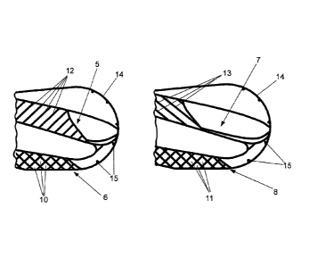
The cutter for electrode graphite shown in the drawings comprises four
equidistant
spaced flutes 1, 2, 3, 4, as shown in particular in Fig. 1, which mutually
space
machining lands 5, 6, 7, 8 in the circumferential direction, which lands are
positioned around a core segment of the cutter for electrode graphite. As can
be
seen in Figs. 2-5, two of the machining lands 5, 6, 7, 8 are formed as rough-
machining lands 6, 8 with teeth 10, 11 forming a circumferential file, wherein
the
CA 2987541 2018-05-09
10
I
other two are fine-machining lands 5, 7 with circumferential exterior grooves
which
space exterior lands from each other, which each carry a circumferential
cutting
edge 12, 13. The teeth 10, 11 and the circumferential cutting edges 12, 13 are
denoted in Figs. 6 and 7 and are each disposed in a circumferential working
area
which is enveloped by an (imaginary) cylindrical exterior sleeve or shell.
In this case, the cutter for electrode graphite has a tool tip designed as a
ball head
section 9, in which the machining lands 5, 6, 7, 8 have an outer contour
following a
ball head radius. In this case, on the rough-machining lands 6, 8, the working
areas
with the teeth 10, 11 extend into the ball head section 9. While one of the
working
areas extends with left-twisted, i.e. pressing, smoothing edges on the post-
machining land 5 extend into the ball head section 9, the working area with
right-
twisted smoothing edges 13 on the other fine-machining land 7 ends already
before
the ball head section 9, i.e. further back. This avoids that in the ball head
section
mainly used to work out filigree geometries a strong pulling load is applied
to the
electrode graphite, which is much more pressure-stable than tension-stable, so
that
filigree geometries can be produced with the ball head section.
In the ball head section 9, however, in the areas adjoining the working areas
of the
machining lands 5, 6, 7, 8 at the tip side, the edges at the transition point
extending along the ball head radius from the circumferential side to each
leading
flute are sharp, i.e. formed as cutting edges 14, as also shown in the Figs. 6
and 7.
The cutting edges 14 are additionally provided with chip breaker grooves 15 in
order to reduce the cutting pressure.
Deviations and modifications of the embodiments shown are possible without
departing from the scope of the invention.
CA 2987541 2018-05-09