Note: Descriptions are shown in the official language in which they were submitted.
CA 02987546 2017-11-28
WO 2016/024123 PCT/GB2015/052348
DOWNHOLE WELL TOOLS AND METHODS OF USING SUCH
Field of the Invention
The present invention relates to downhole well tools suitable for use in a
variety of
operations within oil and gas wells.
Background of the Invention
In order to access oil and gas deposits located in underground formations it
is
necessary to drill bore holes into these underground formation and deploy
production
tubing to facilitate the extraction of the oil and gas deposits.
Additional tubing, in the form of well lining or well casing, may also
deployed in
locations where the underground formation is unstable and needs to held back
to
maintain the integrity of the oil/gas well.
During the formation and completion of an oil/gas well it is crucial to seal
the annular
space created between the casing and the surrounding formation. Also the
annular
space between the different sizes casings used as the well is completed.
Additionally
the annular space between the production tubing and said casing needs to be
sealed. Further seals may be required between the underground formation and
the
additional tubing.
One of the most common approaches to sealing oil/gas wells is to pump cement
into
the annular spaces around the casing. The cement hardens to provide a seal
which
helps ensure that the casing provides the only access to the underground oil
and gas
deposits. This is crucial for both the efficient operation of the well and
controlling any
undesirable leakage from the well during or after the well is operated.
Eventually, once the necessary tubing is secured within an oil or gas well,
the
operation of a well can commence and extraction can begin. Over the
operational
lifetime of an oil/gas well situations can arise where it is necessary to
deploy
downhole tools into the tubing.
One common task is the carrying out of repairs to the tubing, which due to the
downhole environment can develop fractures/leaks over time. Another common
task
-1-
CA 02987546 2017-11-28
WO 2016/024123 PCT/GB2015/052348
is to isolate (whether temporary or semi-permanent) a region of a well from
the rest
of the production tubing.
Various downhole tools are employed in such situations, with some of the most
commonly used including bridge plugs, patches, scab and straddles. In order to
secure the downhole tool within a well such tools are typically provided with
hydraulically actuated means that can be operated to engage with the surface
of a
surrounding tubing (e.g. a well casing, liner or production tubing).
A plurality of these engagement means, which are commonly referred to as
'dogs' or
'slips', are normally provided on a downhole tool so that once the tool is in
place they
can be actuated to lock the tool in position relative to the surrounding
tubing.
Once the required task has been completed by the downhole tool the 'dogs' or
'slips'
can be retracted and the tool can be retrieved from the well.
Although the 'dogs' or 'slips' are suitable to retain the position of a
downhole tool
within a well they are not capable of providing a gas tight seal with the
surrounding
tubing. In view of this, on occasions where a gas tight seal is desirable the
downhole
tool is provided with additional sealing means. This can increase the
possibility for a
malfunction of the downhole tool.
Some types of downhole tools, such as expandable patches, are secured in
position
by expanding the main body of the downhole tool so that it pushes against the
inner
surface of the outer tubing.
Summary of the Invention
The present invention seeks to utilise alternative means for securely
positioning
downhole tools within oil or gas wells that provide a viable alternative to
the systems
(such as hydraulically actuated means; e.g. 'dogs', 'slips') commonly used in
existing
downhole tools.
To this end the present invention employs the use of eutectic/bismuth based
alloy
annular packers described hereinafter as an alternative means for temporarily
or
permanently securing a downhole tool within an oil or gas well.
-2-
CA 02987546 2017-11-28
WO 2016/024123 PCT/GB2015/052348
The annular packers described throughout essentially consist of a reservoir of
eutectic/bismuth based alloy that is mounted on the outer surface of a section
of
tubing. The alloy can be melted to form a seal between the outer surface of
the
tubing and the inner surface of surrounding tubing.
It is appreciated that the seal formed can be used to not only provide a gas
tight seal
but also secure the inner tubing in position within the outer tubing. In view
of this and
to avoid any confusion the annular packers that are used in the downhole tools
of the
present invention can also be referred to as annular seals or annular sealing
means.
The terms 'annular packer', 'annular sealing means' and 'annular seal' are
therefore
considered to be interchangeable when used in connection the downhole tools of
the
present invention.
The general concept of the annular packers, which are described herein for
information purposes only, are the subject a separate patent application.
In order to aid the description of the downhole tools of the present invention
a gas or
oil well tubing having an annular packer mounted thereon, wherein the annular
packer is formed from a eutectic or other bismuth based alloy, is described.
In its broadest sense the tubing may refer to a section of welling lining, a
section of
well casing or a section of production tubing.
Mounting the annular packer on the tubing that is then deployed in the
formation of
an oil/gas well means that the alloy is already in situ within the well. In
this way,
when a leak is detected it can be remedied by simply heating the region of the
tubing
where the annular packer is mounted.
It is appreciated that, in use, the tubing could be effectively deployed just
above the
cement seal so that when melted the alloy of the annular packer can quickly
and
easily flow into any cracks/gaps formed in the cement.
Alternatively the tubing could be completely surrounded by and embedded within
the
cement.
It is also envisioned that the tubing might effectively be deployed well above
the
cement seal or even in wells that do not contain a cement seal.
-3-
CA 02987546 2017-11-28
WO 2016/024123 PCT/GB2015/052348
In those cases where a cement seal is employed it is envisioned that whilst
the
tubing of the first aspect of the present invention may be deployed after the
cement
seal has been formed, it is considered more likely that the tubing may be
deployed
within a well bore before the cement seal has been formed.
To this end the annular packer may preferably be provided with one or more
conduits running substantially parallel to the tubing. The conduits facilitate
the
passage of cement beyond the annular packer when it is poured or pumped into
the
annular space to form the aforementioned seal.
The conduits may be provided as channels in the inner and/or outer
circumferential
surface of the annular packer. Alternatively the conduits may be provided as
through
holes in the main body of the annular packer.
In order for the packer to create a gas tight seal it is necessary to remove
the cement
from any conduits. This can be achieved by squeezed the cement out while the
cement is still in liquid form. Alternatively the cement in the conduits can
be broken
once it has solidified.
In one variant the annular packer may be mounted on the inner surface of the
tubing.
It is envisioned that this arrangement is particularly suitable when the
tubing is a well
casing or well lining.
In an alternative variant the annular packer may be mounted to the outer
surface of
the tubing.
Preferably, the annular packer may comprise multiple component parts which are
combinable to form the complete annulus when mounted on the tubing. In this
way
the production step of mounting the annular packer on the tubing is made
quicker
and easier.
Further preferably the multiple component parts may consist of two or more
ring
segments which can be connected together to form a complete annular packer
that
encircles the tubing.
This external mounting arrangement is considered particularly suitable when
the
tubing is production tubing. However, as will now be explained, the inventors
have
-4-
CA 02987546 2017-11-28
WO 2016/024123 PCT/GB2015/052348
conceived a number of related applications made possible by locating an alloy
annular packer or annular seal on the outer surface of the tubing.
In a first aspect, the present invention provides a downhole tool comprising
tubing
with at least one annular sealing means mounted on an outer surface thereof,
wherein the annular sealing means is formed from a eutectic/bismuth based
alloy.
The provision of at least one annular sealing means on the outer surface of
the
tubing enables the formation of an annular seal between the outer surface of
the tool
and the inner surface of a surrounding well tubing/casing. It is appreciated
that the
ability to set and unset the annular seal with a heater deployed within the
well
facilitates the easy deployment and removal of these downhole tools, which are
normally, although not always, only required for a limited period of time.
Preferably in addition to said one or more annular sealing means, which are
used to
secure the downhole tool in position, the downhole tool may be provided with a
separate region of eutectic/bismuth based alloy that is distinct from the
annular
sealing means.
It is envisaged that the additional alloy region can be heated in a separate
operation
(possibly once the downhole tool has been set in position) in order to carry
out a
patch repair of a leak in the surrounding well casing. In this way the
downhole tool
can be employed as a patch.
Alternatively or additionally the tubing may further comprise tool engagement
means
located within the tubing. Providing tool engagement means within tubing
before it is
deployed with an oil/gas well enables the subsequent deployment and secure
mounting of operational tools (e.g. such as valves and flow rate monitors)
within the
well.
It is also envisaged that the tool engagement means might also be used by any
heater tool used to melt the eutectic/bismuth based annular packer/annular
sealing
means.
It is further envisioned that the tool engagement means might also be used to
securely retain a temporary plug, the interior of the tube could be fitted
with an easy
to break section (.e.g. a burst disc) which allows the well to be opened up
again with
-5-
CA 02987546 2017-11-28
WO 2016/024123 PCT/GB2015/052348
reduced operation costs The tool could be set either in situ down the well or
prefabricated prior to deployment down the well.
Further preferably the tool engagement means are located on the inner surface
of
the tubing that is proximate to the externally mounted annular packer.
Alternatively
the tubing may be provided with magnetic heater alignment means that enable a
sensor on the heater to detect when it is correctly aligned with the tubing's
externally
mounted annular seal(s).
In order to enable the downhole tool to be delivered down the well the tool is
preferably provided with attachment means for connecting the tool to a
delivery tool,
for example by way of a wire line or a setting tool. Further preferably the
attachment
means comprise shear pins so that the wire line can be retrieved from the well
once
the downhole tool has been secured in position by the annular sealing means.
Preferably the tubing may also have a weak point just above the 'slump' line
of the
set alloy. In this way the tool length can be reduced after setting, which
reduces the
operational costs if the tool needs to be removed in future, e.g. by milling.
Preferably the tubing is formed from two sections that are held together, at
least in
part, by a eutectic/bismuth based alloy. Further preferably the attachment
means for
connecting the downhole tool to the delivery tool (e.g. via a wire line) can
be located
on the section of the tubing that is released/revealed when the alloy sags.
In this way a section of the tubing can be retrieved from the well. This is
considered
particularly advantageous because it reduces the amount of material that needs
to
be removed from the well in the event that milling or drilling is used.
Further preferably the section of the tubing that remains in the well may be
formed
from a softer material (e.g. aluminium) than the section with the delivery
tool
attachment means. In this way any subsequent milling/drilling out of the
downhole
tool is made easier/quicker.
Preferably the section of the tubing that remains in the well may have walls
that are
thinner that at least a portion of the section with the delivery tool
attachment means.
Once again this will facilitate easier milling/drilling out of the downhole
tool.
-6-
CA 02987546 2017-11-28
WO 2016/024123 PCT/GB2015/052348
It is appreciated that varying the length of the tubing can provide a variety
of
downhole tools that range from patches, which have a shorter length of tubing,
to
straddles, which have a considerably longer length of tubing, and scabs, which
can
be have length of tubing that is somewhere in between. These various types of
downhole tool are all considered to fall within the scope of the present
invention.
It is appreciated that the size, number and positioning of the
eutectic/bismuth based
alloy annular sealing means provided on the outer surface of the tubing will
vary from
tool to tool. For example it is considered appropriate that the size (and
possibly the
number) of the annular sealing means used on a straddle would be greater than
required for a patch due to the much greater weight load being carried by the
annular
seals formed between the outer well tubing and the downhole tool.
It is envisioned that an appropriately dimensioned tubing with the tool
engagement
means and an annular sealing means could be deployed within an existing
oil/gas
well and secured in place using the alloy to temporarily install a control
tool(such as
a valve), a measuring tool(e.g. flow rate) or even a breakable plug at a
target
location.
To this end a second aspect of the present invention relates to a well tool
deployment adaptor comprising the tubing of the first aspect of the present
invention,
wherein the annular sealing means is mounted on the outer surface of the
tubing and
tool engagement means are located within the tubing.
In the third aspect of the present invention there is provided a breakable
eutectic/bismuth based alloy well plug, said plug comprising: an open-ended
tubular
plug body having eutectic/bismuth base alloy mounted on the outside thereof;
and
wherein passage through the tubular plug body is blocked by a breakable
plugging
member.
Preferably the breakable plugging member is provided in the form of a burst
disc.
The present invention also provides a method of manufacturing the downhole
tool of
the present invention, which in turn can be further adapted for use in various
embodiments thereof.
-7-
CA 02987546 2017-11-28
WO 2016/024123 PCT/GB2015/052348
Specifically the present invention provides a method of manufacturing a
downhole
tool for use in oil and gas wells, said method comprising: providing a length
of tubing;
mounting at least eutectic/bismuth based alloy annular sealing means to an
outer
surface of the tubing.
Preferably the annular sealing means is provided in the form of multiple
component
parts and the step of mounting the annular sealing means to the tubing
involves
securing the component parts together around the circumference of the tubing
to
complete the annulus. This approach is considered most appropriate for
producing
the variants of the tubing according to the present invention that has the
annular
sealing means mounted on the outer surface thereof.
Preferably the method of manufacturing the oil/gas well tubing further
comprises
providing multiple conduits in the annular sealing means. As detailed above,
the
conduits may be in the form of channels in the inner and outer surface of the
annular
sealing means. Alternatively the conduits may possibly be in the form of
through
holes running through the main body of the alloy.
The present invention also provides a method of sealing a leak in a completed
oil/gas well using the downhole tool of the present invention by heating the
annular
sealing means in situ to melt the alloy and seal the leak.
Preferably a heating tool, such as a chemical heater, can be deployed down the
well
to apply heat to the eutectic/bismuth based annular sealing means and cause it
to
melt. Alternatively the tubing may further comprise heating means that can be
activated remotely to melt the alloy. In such an arrangement the heating means
are
preferably in the form of a chemical heat source.
Preferably the method involves the step of removing the downhole tool once the
leak
in the tubing has been sealed with alloy. Further preferably the downhole tool
is
removed by milling/drilling. This approach is considered particularly
beneficial
because it enables the tubing to be returned to its original operational
diameter,
which is in contrast to other patch operations wherein the patch is left in
situ to cover
the leak.
-8-
CA 02987546 2017-11-28
WO 2016/024123 PCT/GB2015/052348
Brief Description of the Drawings
The various aspects of the present invention will now be described with
reference to
the drawings, wherein:
Figure 1 is a diagrammatic representation of the key stages of the deployment
and operation of the oil/gas well tubing of an embodiment of the first aspect
of the
present invention;
Figure la is a diagrammatic representation of an alternative deployment of
the tubing with an annular packer;
Figure 1 b is a diagrammatic representation of a second alternative
deployment of the tubing with an annular packer;
Figure 2 shows a perspective view of an annular packer being used as a
annular sealing means mounted on the outer surface of tubing which can form
the
basis for a downhole tool in accordance with the present invention;
Figure 3 shows an end view of one variant of the annular sealing means
shown in Figure 2;
Figure 4 shows an end view of a second variant of the annular sealing means
shown in Figure 2;
Figure 5 shows a diagrammatic cross-sectional representation of a well tool
deployment adaptor according to the second aspect of the present invention;
Figure 5a shows a diagrammatic representation of the key stages of the
deployment and operation of a further enhanced embodiment of the second aspect
of the present invention;
Figure 6 shows a diagrammatic cross-sectional representation of the key
stages of the deployment of a straddle downhole tool according to the present
invention.
-9-
CA 02987546 2017-11-28
WO 2016/024123 PCT/GB2015/052348
Detailed Description of the Various Aspects of the Present Invention
The various aspects will now be described with reference to the Figures, which
provide a collection of diagrammatic representations of embodiments of the
each
aspect of the present invention to aid the explanation of their key features.
One of the central features of a number of the aspects of the present
invention is
formation of prefabricated oil/gas tubing with a eutectic/bismuth based alloy
annular
packer mounted to the said tubing. Although the term annular packer is used it
is
appreciated that the terms annular sealing means, annular seal and thermally
deformable annulus packer may also employed depending on the context of the
embodiment being described. The terms can therefore be used interchangeably.
The term prefabricated is intended to cover situations where the annular
packer/annular sealing means is mounted on the tubing either in a factory or
on site,
but always before the tubing is deployed down a well bore. This is clearly
distinct
from existing uses of alloy as a sealant, wherein the alloy is deployed
separately
from the tubing at a later stage ¨ which is usually after completion of the
well.
It will be appreciated that, unless otherwise specified, the materials used to
manufacture the components of the various apparatus described hereinafter will
be
of a conventional nature in the field of oil/gas well production.
The downhole tools of the present invention utilise alloy annular packers or
annular
sealing means rather than more traditional mechanical means (e.g. 'dogs' or
'slips')
to retain the tools in position within a well. In order to better understand
the annular
packers upon which the annular sealing means present invention is based such
will
now be described with reference to figures 1-4.
Figure 2 shows an oil/gas well tubing 1 suitable for use with the downhole
tools of
the present invention in the form of a length/section of pipe 2 with a
eutectic/bismuth
based alloy annular packer 3 mounted on the outside thereof.
Although not shown in the Figures it is envisioned that the externally mounted
annular packer might preferably be formed from multiple component parts that
combine to surround the length of production pipe 2 so that the process of
mounting
(and possibly remounting) the annular packer is made easier.
-10-
CA 02987546 2017-11-28
WO 2016/024123 PCT/GB2015/052348
As will be appreciated from Figure 1 the diameter of the annular packer 3 is
sufficient
to provide a close fit with the outer wall of the well 5, which may be
provided by a
rock formation 4 or as appropriate a well casing or lining.
In order to explain the use of the tubing 1 reference is made to Figure 1,
which
shows three key stages in the working life of the tubing 1. In the first stage
the tubing
1, which comprises the section of tubing 2 with the annular packer 3 mounted
on the
outer surface, is attached to tubing 6 and delivered down the well bore 5 that
has
been created in the underground formation 4 using conventional means.
It is appreciated that tubing 1 and 6 are typically connected together above
ground
and then deployed down the well. However in order to clearly illustrate that
tubing 1
and 6 are initially distinct they are initially shown in figure 1 as being
separate.
In the reference Figures the tubing 1 is attached to the top of the tubing 6
that is
already secured in the well 5. It is envisioned that advantageously the tubing
1 of the
present invention may be connected to existing production tubing 6 using a
collar
joint, for example.
Once the production pipework, which comprises tubing 1 and 6, has been
deployed
within the well 5 cement 7 can be poured or pumped into the annular space
between
the formation 4 and the pipework (or, if appropriate, between a well
casing/lining and
the pipework). Once set the cement 7 will seal the well 5 so that the only
access to
the oil/gas deposit is via the production tubing 1, 6.
In the event that a crack or gap develops in the cement seal and forms a leak
a
heater 8 can be deployed down the well using a wire line 9 or coil tubing, for
example, to a target region inside the tubing 1 that is proximate to the
eutectic/bismuth based alloy annular packer 3. Once in place the heater 9 can
be
activated to melt the alloy 3, which causes it to turn into a liquid and flow
into the
cracks/gaps in the cement plug 7.
When the alloy 3 of the annular packer cools it expands and plugs the
cracks/gaps
and reseals the cement plug 7 and stops the leak.
It is appreciated that various annular spaces are created during the formation
of a
well and it is envisioned that the present invention can therefore be usefully
-1 1-
CA 02987546 2017-11-28
WO 2016/024123 PCT/GB2015/052348
employed in variety of different arrangements without departing from the scope
of
the present invention.
In the referenced Figures the cement is poured (or pumped) into the annular
space
after the tubing 1, with its annular packer 3, has been deployed within the
well.
In arrangements where the diameter of the annular packer 3 is close to the
internal
diameter of the rock formation 4 (or well casing/lining ¨not shown) it is
considered
advantageous to provide the annular packer 3 with conduits to facilitate the
passage
of cement through and around the annular packer 3 so that it can reach the
lower
regions of the well 5.
It is envisioned that rather than being deployed above the level of the cement
the
tubing 1 may also be completely surrounded by and embedded within the cement
7.
Figures la and lb show such arrangements.
The embodiment of the tubing shown in Figure la has an annular packer 3 of a
reduced diameter that does not extend all the way to the outer formation (or
casing).
In is envisioned that such embodiment is suitable for sealing micro annuli
leaks; such
as those formed by constant expansion and contraction of the production tubing
(see
above).
The embodiment shown in Figure lb has an annular packer 3 with a diameter that
extends to the surrounding formation (or casing). It is envisioned that this
embodiment is more suitable for repairing cracks that extend across the entire
cement seal.
Figure 3 shows a first variant of the annular packer 3, which is provided with
a
plurality of through holes 10, that could be employed as an annular sealing
means in
the downhole tools of the present invention. The through holes 10 are arranged
to
permit the passage of wet cement through the main body of the annular packer
3.
Figure 4 shows a second variant of the annular packer 3, which is provided
with a
plurality of channels 11 in the outer surface of the annular packer 3. It is
envisaged
that both variants might be employed as annular sealing means in the downhole
tools of the present invention, however the provision of conduits is not
considered
crucial to the operation of the downhole tools.
-12-
CA 02987546 2017-11-28
WO 2016/024123 PCT/GB2015/052348
Turning now to Figure 5, in which is shown an embodiment of a downhole tool of
the
present invention in the form of a well tool deployment adaptor 12 according
to a
second aspect of the present invention. It will be appreciated that the main
components of the adaptor 12 are essentially the same as the tubing shown in
Figures 1-4, in that it comprises a length/section of tubing 13 with a
eutectic/bismuth
based annular packer 14 mounted on the outside thereof.
However the adaptor 12 further comprises tool engaging means 15 located inside
the adaptor. The tool engaging means 15 can be of any form provided they are
capable of securely engaging/locating a complementary tool within the tubing
13.
In use the adaptor 12 is deployed within an existing well tubing structure
(e.g.
production tubing) and is maintained in place by heating the region of the
adaptor
proximate to the eutectic/bismuth based alloy and then allowing the alloy cool
and fix
the adaptor in place within the well by the force of the expanded alloy
pressing
against the existing well tubing (not shown).
The adaptor is provided with a skirt or 'cool area' 18 to slow the flow of the
melted
alloy 14 so that it is not lost down the well but instead cools in the target
region.
Further details of suitable skirting can be found in International PCT
Application No.
W02011/151271. It is appreciated that the well fluids will act to quickly cool
the
heated alloy ensuring that it is not is a flowing state for very long.
Although not shown, it is envisaged that the skirt may further comprise a
swellable or
intumescent material that is caused to expand when exposed to heat. This
further
enhances the ability of the skirt to check the flow of the molten alloy so
that it can
cool in the target region.
Once the adaptor is secured in place within the well a complementary tool 16
(examples of which include a valve, a flow rate meter or even a temporary,
breakable plug) can be delivered down the well using delivery means 17 (e.g.
wire
line).
When the time comes to remove the adaptor 12 a heater can be deployed down the
well to engage with the tool engaging means 15, heat the alloy and retrieve
the
adaptor 12.
-13-
RECTIFIED SHEET (RULE 91)
CA 02987546 2017-11-28
WO 2016/024123 PCT/GB2015/052348
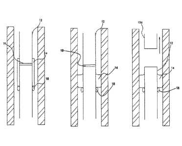
Figure 5a shows a preferred embodiment of the adaptor 12 with the tool
engagement
means hidden to simplify the diagram. The tubular body of the adaptor is
provided
with a weakened point 19. During deployment of the adaptor 12 the weakened
point
is covered by alloy, this gives additional structural support to the adaptor.
Once in situ, and the alloy has been melted to secure the adaptor in place,
the
weakened point 19 is revealed by the alloy 14. This enables the top portion
12a of
the adaptor 12 to be broken off and removed. The removal of the top portion
12a
makes any subsequent operations to remove the adaptor 12 easier due to the
reduced amount of tubing that needs to be milled out.
It is appreciated that the technical benefit achieved by providing the
weakened point
in the adaptor tubing could also be utilised in other aspects of the present
invention ¨
such as the breakable eutectic/bismuth based alloy plug according to the third
aspect of the present invention, for example.
Another embodiment of a downhole tool of the present invention in the form of
a
straddle 171 will now be described with reference to figure 6, which show the
key
stages of a straddle deployment operation.
The straddle 171 is configured to be deployable within a well tubing 170 (e.g.
a well
casing, well lining or other production tubing). The straddle 171, which
essentially
comprises a length of tubing, is provided with two eutectic/bismuth based
annular
sealing means 172, 173.
The annular sealing means 172, 173 are located at the leading and trailing end
regions of the straddle. However it is envisaged that additional annular
sealing
means may be provided at points along the length of the straddle's outer
surface as
required (i.e. when the straddle is of an extended length.
Once the straddle reaches the target region within the well a heater 174 can
be
operated to heat the annular sealing means so that annular seals can be formed
between the outer surface of the straddle 171 and the inner surface of the
outer
tubing 170.
In figure 6 the embodiment shown has uses a heater that has two separate
heating
modules 175, 176. In this way the straddle can be deployed by the heater in a
single
-14-
CA 02987546 2017-11-28
WO 2016/024123 PCT/GB2015/052348
deployment (i.e. without having to retrieve the heater from the well and
recharge the
heat source. It is envisaged that the heating modules are preferably chemical
heat
sources, although it is appreciated that alternative heat sources could also
be
employed without departing from the scope of the present invention.
Once the first heating module 175 is aligned with the annular sealing means
172
located at the trailing end of the straddle 171 the heat is activated and the
alloy of
the annular sealing means 172 is melted and allowed to sag. As the alloy sags
and
cools an annular seal is formed between the straddle 171 and the outer tubing
170.
Although not shown in figures it is envisioned that the heater and the
straddle are
preferably deployed down the well as a single unit in which the first heating
module
175 is aligned with annular sealing means 172.
Once the first heating module 175 has finished and the upper annular seal 172a
has
been formed, and the straddle is secured in position in the well, the heater
174 can
be detached from the straddle 171 by partially retrieving the heater using the
wire
line.
Once the heater has been released from the straddle it can be deployed further
down the well via the internal cavity of the straddle 171. As will be
appreciated
although the heater 174 can be delivered using standard delivery means such as
a
wire line, alternative systems can be used without departing from the present
invention.
Once the second heating module 176 is aligned with lower annular sealing means
173 the heating module can be activated and the process of forming an annular
seal
is repeated at the lower end of the straddle to form the annular seal 173a.
Once the second annular seal 173a has been set the heater 174 is retrieved
from
the well using the wire line, for example.
Although the straddle shown in figure 6 is provided with two annular sealing
means it
is envisioned that additional annular sealing means may be provided on the
outer
surface thereof. It is further envisioned that the heater used to deploy such
straddles
would advantageous be provided with a corresponding number of heater modules
so
that the straddle can be fully deployed by the heater in a single visit.
-15-