Note: Descriptions are shown in the official language in which they were submitted.
CA 02987555 2017-11-28
P0462181
DESCRIPTION
COOKING APPARATUS
TECHNICAL FIELD
The present disclosure relates to a cooking apparatus that heats
foodstuffs inside the heating chamber by means of radiant heat of the
heater.
BACKGROUND
This type of cooking apparatus has been using heater control in
which the mode is changed from the preheating mode to the cooking
mode at the time before preheating ends to stabilize heat distribution
inside the heating chamber at the time when starting cooking
foodstuffs and thus to suppress uneven browning (refer to PTL 1 for
example).
FIG. 8 shows changes of the temperature inside the heating
chamber to output power of the heater in an existing cooking apparatus
described above. As shown in FIG. 8, the existing heater control
changes the heater output from 1,900 W (in the preheating mode) to
1,150 W (in the cooking mode) at the time before preheating ends.
Citation List
Patent Literature
PTL 1: Japanese Utility Model Unexamined Publication No.
H05-032905
1
=
SUMMARY
In the previous heater control described above, the heater repeats
turning on and off before preheating ends and until the cooking mode
starts after preheating ends (hereinafter, referred to as "on standby
after preheating"). Thus, the surface temperature of the heater is
high if the heater is on at the time of cooking start, and the surface
temperature of the heater is low if the heater is off at the time of
cooking start.
Accordingly, the difference in the surface temperature at the time of
cooking start causes uneven browning. Hence, lowering the output of
the heater to stabilize heat distribution inside the heating chamber
before preheating ends requires a longer time to complete preheating.
An object of the disclosure, to solve the above-described problems, is to
suppress uneven browning even if cooking starts immediately after
preheating ends without requiring a long time to complete preheating
in order to stabilize heat distribution inside the heating chamber.
A cooking apparatus according to one aspect of the present disclosure
includes a heating chamber in which an object to be heated is rested, a
radiant heater unit provided inside the heating chamber and operating
in the preheating and cooking modes, and a control unit controlling the
radiant heater unit. The control unit is configured to make the
radiant heater unit operate in the standby mode (i.e., a mode after the
preheating mode ends and until the cooking mode starts).
According to this aspect, the surface temperature of the radiant heater
unit is kept high during the standby mode (i.e., a mode after the
preheating mode ends and until the cooking mode starts) to suppress
2
CA 2987555 2019-02-15
,
,
insufficient heating or uneven browning due to variations in the
surface temperature of the radiant heater unit when cooking starts.
2A
CA 2987555 2019-02-15
CA 02987555 2017-11-28
P0462181
BRIEF DESCRIPTION OF DRAWINGS
FIG. 1 is an external perspective view of a cooking apparatus
according to an exemplary embodiment of the present disclosure.
FIG. 2 is a perspective view of the cooking apparatus according to
the embodiment, with its door open.
FIG. 3 is a front view of the cooking apparatus according to the
embodiment, with its door open.
FIG. 4 is a front-back sectional view of the cooking apparatus
according to the embodiment.
FIG. 5 is a front view of the convection device provided in the
cooking apparatus according to the embodiment.
FIG. 6A illustrates changes of the temperature inside the heating
chamber to output voltage of the grill heater after preheating starts at
room temperature inside the heating chamber.
FIG. 6B illustrates changes of the temperature inside the heating
chamber to output voltage of the grill heater after preheating starts at
middle temperature inside the heating chamber.
FIG. 6C illustrates changes of the temperature inside the heating
chamber to output voltage of the grill heater after preheating starts at
high temperature inside the heating chamber.
FIG. 7 shows results of cooking according to the embodiment.
FIG. 8 illustrates changes of the temperature inside the heating
chamber to output voltage of the grill heater in an existing cooking
apparatus.
DETAILED DESCRIPTION OF THE PREFERRED EMBODIMENT
3
CA 02987555 2017-11-28
P0462181
A cooking apparatus according to the first aspect of the present
disclosure includes a heating chamber in which an object to be heated
is rested, a radiant heater unit provided inside the heating chamber
and operating in the preheating and cooking modes, and a control unit
controlling the radiant heater unit. The control unit is configured to
make the radiant heater unit operate in the standby mode (i.e., a mode
after the preheating mode ends and until the cooking mode starts).
According to this aspect, the surface temperature of the radiant
heater unit is kept high during the standby mode (i.e., a mode after the
preheating mode ends and until the cooking mode starts) to suppress
insufficient heating or uneven browning due to variations in the
surface temperature of the radiant heater unit when cooking starts.
According to a cooking apparatus of the second aspect of the
disclosure, the control unit of the first aspect is configured to set the
output voltage of the radiant heater unit in the preheating mode in
response to the temperature inside the heating chamber when the
preheating mode starts. This aspect suppresses insufficient heating
or uneven browning regardless of the chamber-inside temperature
when preheating starts.
According to a cooking apparatus of the third aspect of the
disclosure, the control unit of the second aspect is configured to control
the radiant heater unit so that the output voltage in the preheating
mode is kept unchanged in the standby mode and the output voltage is
changed when the cooking mode starts. This aspect stabilizes the
chamber-inside temperature immediately after preheating ends to
suppress insufficient heating or uneven browning.
Hereinafter, a description is made of a cooking apparatus
4
CA 02987555 2017-11-28
P0462181
to an embodiment of the disclosure with reference to the attached
drawings.
In this embodiment, cooking apparatus 10 is a business-use
microwave oven used in a store such as a convenience store and a fast
food store and executes the microwave heating mode, grill mode, and
convection mode. Cooking apparatus 10 has a maximum output of
2,000 W and its output is changeable in multiple levels.
FIG. 1 is an external perspective view of cooking apparatus 10
according to the exemplary embodiment, with door 3 on its front
surface closed. FIGs. 2 and 3 are respectively a perspective view and
a front view of cooking apparatus 10, with door 3 open. FIG. 4 is a
front-back sectional view of cooking apparatus 10.
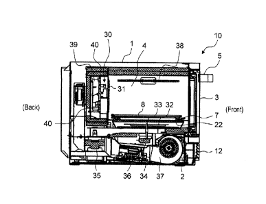
As shown in FIGs. 1 and 2, cooking apparatus 10 includes main
unit 1, machine compartment 2, and door 3. Machine compartment 2
is provided under main unit 1 so as to support main unit 1. Door 3 is
provided on the front surface of main unit 1 so as to close heating
chamber 4. Detachable front grill panel 12 is provided on the front
surface of machine compartment 2.
As shown in FIG. 2, heating chamber 4 is formed inside main unit
1. Heating chamber 4 has a substantially rectangular parallelepiped
space with an opening in its front surface in order to rest an object to
be heated inside heating chamber 4.
In this embodiment, the side of heating chamber 4 in which the
opening is formed is defined as the front side of cooking apparatus 10;
the opposite, as the rear side of cooking apparatus 10. The right side
of cooking apparatus 10 viewed from the front is simply defined as the
right side; the left side, the left side.
5
CA 02987555 2017-11-28
P0462181
Door 3 is attached with hinges provided under the opening of
heating chamber 4. Door 3 is opened and closed vertically using
handle 5 provided on door 3. With door 3 closed, heating chamber 4
becomes an enclosed space for heating the object rested in heating
chamber 4 with microwaves for example.
In this embodiment, a control panel is installed on the right front
side of main unit 1. The control panel is provided with operation unit
6. Operation unit 6 is provided with operation keys and a display unit
for setting conditions of heat-cooking. Behind the control panel, a
control unit (unillustrated) is provided that receives a signal from
operation unit 6 and controls the display unit.
As shown in FIG. 2, tray 7 made of ceramics and wire rack 8 made
of stainless steel are disposed inside heating chamber 4 in a
containable manner. Concretely, tray 7 is made of cordierite (ceramics
with a composition of 2Mg0 = 2A1203 = 5Si02).
Wire rack 8 is a rest unit made of a net-shaped material on which
an object to be heated is rested. Wire rack 8 allows hot airflow to be
efficiently circulated even to the undersurface of the object. Tray 7 is
placed under wire rack 8 so as to receive fat for example dropping from
the object.
As shown in FIG. 4, machine compartment 2 placed under heating
chamber 4 is provided therein with magnetron 35, inverter 36, and
cooling fan 37. Magnetron 35 is a microwave generating unit that
generates microwaves. Inverter 36 is controlled by the control unit to
drive magnetron 35. Cooling fan 37 is controlled by the control unit to
cool the inside of machine compartment 2.
Microwaves generated by magnetron 35 travel through the
6
CA 02987555 2017-11-28
P0462181
waveguide and are radiated into heating chamber 4 through the
microwave emission hole formed in the waveguide and the opening
formed in the bottom surface of heating chamber 4. Stirrer 32 is
controlled by the control unit to stir microwaves radiated into heating
chamber 4. Cooking apparatus 10 thus microwave-heats an object
contained in heating chamber 4.
Cooking apparatus 10 includes grill heater 38, which is a radiant
heater unit provided near the ceiling of heating chamber 4. In this
embodiment, grill heater 38 is a sheath heater. The control unit
makes grill heater 38 operate and controls the grill mode. In the grill
mode, an object rested in heating chamber 4 is radiant-heated by
radiant heat of grill heater 38.
As shown in FIGs. 3 and 4, cooking apparatus 10 includes
convection device 30 that is provided behind back surface wall 31 of
heating chamber 4 and sends hot airflow into heating chamber 4 to
convectively heat an object. Convection device 30 draws air inside
heating chamber 4 from the central part of back surface wall 31, heats
the air to produce hot airflow, and blows it out from the bottom of back
surface wall 31 into heating chamber 4. The hot airflow sent into
heating chamber 4 becomes a circulating flow in there.
Inside convection device 30, a thermistor (unillustrated) is
provided that is a temperature sensor detecting the temperature of the
space inside convection device 30. This thermistor detects a signal
corresponding to the temperature of the space inside convection device
30. The control unit makes convection device 30 operate in response
to this signal.
Cooking apparatus 10 performs microwave heating, radiant
7
CA 02987555 2017-11-28
P0462181
heating, and heating by circulating hot airflow separately, or performs
at least two of the three types of heating simultaneously.
In this embodiment, two magnetrons 35 are used (unillustrated),
with a total output power of 1,200 W to 1,300 W. Microwaves output
from two magnetrons 35 respectively travel through two waveguides,
pass through openings formed in the waveguides and in the bottom
surface of heating chamber 4, are stirred by stirrer 32, and are
radiated into heating chamber 4.
To drive two magnetrons 35, two inverters 36 are provided inside
machine compartment 2. Inside machine compartment 2, cooling fans
37 are placed in order to cool magnetron 35 and inverter 36. In this
embodiment, for two cooling fans 37 to cool one set of magnetron 35 and
inverter 36, a total of four cooling fans 37 are provided.
Cooling fan 37 draws outside air from front grill panel 12 provided
on the front surface of machine compartment 2 and sends the air to the
rear to cool inverter 36, magnetron 35, and other components. In
machine compartment 2, a power circuit board is disposed and a
cooling fan for cooling the power circuit board is further provided.
In this embodiment, four cooling fans 37 for inverter 36 and
magnetron 35, and a cooling fan for the power circuit board are
multiblade fans. A total of five rotation shafts of the cooling fans are
disposed linearly.
The air that has travelled to the rear inside machine compartment
2 passes through an exhaust duct disposed on the back surface of main
unit 1, moves through between the ceiling of heating chamber 4 and the
top surface wall of main unit 1, and is discharged from the front side of
main unit 1. This way prevents main unit 1 from becoming too hot.
8
CA 02987555 2017-11-28
P0462181
Hereinafter, a more detailed description is made of the internal
structure of cooking apparatus 10 using FIG. 4.
As shown in FIG. 4, tray cradle 22 is made of a plate material
made of ceramics that is microwave-transmissive and is placed on the
bottom surface of heating chamber 4. Tray 7 is rested on tray cradle
22. Stirrer 32 is provided between tray cradle 22 and the bottom
surface of heating chamber 4. Stirrer 32 is a wafter that rotates
around stirrer shaft 33 in order to stir microwaves. Motor 34 is
provided inside machine compartment 2 and rotarily drives stirrer 32.
Back surface wall 31 of heating chamber 4 has a large number of
openings formed by punching. Behind back
surface wall 31,
convection device 30 is provided that takes in air inside heating
chamber 4, heats the air, and sends out the hot airflow into heating
chamber 4. The space where convection device 30 is placed is
separated from heating chamber 4 by back surface wall 31 and
communicates with heating chamber 4 through the opening formed in
back surface wall 31.
As shown in FIG. 4, convection device 30 has hot airflow
generation mechanism 39 for generating hot airflow. Hot airflow
generation mechanism 39 takes in air inside heating chamber 4, heats
the air to generate hot airflow, and sends it out into heating chamber 4.
This produces circulating hot airflow inside heating chamber 4.
FIG. 5 is a front view of convection device 30. As shown in FIG. 5,
hot airflow generation mechanism 39 includes convection heater 40,
circulation fan 41, a fan drive unit (unillustrated) that rotarily drives
circulation fan 41, and first and second hot airflow guides 43 and 44
that guide hot airflow in hot airflow generation mechanism 39.
9
CA 02987555 2017-11-28
P0462181
Convection heater 40, which is a sheath heater, heats air inside
convection device 30. To increase the contact area with air, convection
heater 40 is spirally formed at the center (corresponding to the central
part of the heating chamber) of convection device 30.
Circulation fan 41 is a centrifugal fan that takes in air at its
central part and sends out the air in the centrifugal direction.
Circulation fan 41 is disposed behind convection heater 40 and is
driven by the fan drive unit provided behind circulation fan 41. In
this embodiment, circulation fan 41 rotates in the direction of arrow R
(refer to FIG. 5). The control unit controls convection heater 40 and
the fan drive unit.
Hereinafter, a description is made of the operation and functions of
the cooking apparatus using FIGs. 6A through 6C.
FIG. 6A illustrates changes of chamber-inside temperature CT of
heating chamber 4 to output power HP of grill heater 38 after
preheating starts at around 25 C (referred to as room temperature
hereinafter) of chamber-inside temperature CT.
As shown in FIG. 6A, on starting preheating mode PH, grill heater
38 is turned on with output power HP of 1,000 W, and chamber-inside
temperature CT of heating chamber 4 rises from room temperature.
Although unillustrated, convection device 30 starts its operation
simultaneously with turning on of grill heater 38.
After 5 minutes or more have elapsed since preheating started,
convection device 30 stops and preheating mode PH ends.
Subsequently, grill heater 38 maintains output power HP of preheating.
The time period after preheating mode PH ends and until cooking mode
CK starts is referred to as standby mode WT. In FIG. 6A, after
CA 02987555 2017-11-28
P0462181
approximately 2 minutes of standby mode WT, output power HP of grill
heater 38 drops to 470 W and cooking mode CK starts.
FIG. 6B illustrates changes of chamber-inside temperature CT of
heating chamber 4 to output power HP of grill heater 38 after
preheating starts at around 70 C (referred to as middle temperature
hereinafter) of chamber-inside temperature CT.
As shown in FIG. 6B, on starting preheating mode PH, grill heater
38 is turned on with output power HP of 850 W, and chamber-inside
temperature CT of heating chamber 4 rises from middle temperature.
In other words, at chamber-inside temperature CT of middle
temperature, grill heater 38 is activated with output power HP lower
than that of room temperature. Although unillustrated, convection
device 30 starts its operation simultaneously with turning on of grill
heater 38.
After 5 minutes have elapsed since preheating started, convection
device 30 stops and preheating mode PH ends. Subsequently, grill
heater 38 maintains output power HP of preheating. In FIG. 6B, after
approximately 2 minutes of standby mode WT, output power HP of grill
heater 38 drops to 470 W and cooking mode CK starts.
FIG. 6C illustrates changes of chamber-inside temperature CT of
heating chamber 4 to output power HP of grill heater 38 after
preheating starts at around 150 C (referred to as high temperature
hereinafter) of chamber-inside temperature CT.
As shown in FIG. 6C, on starting preheating mode PH, grill heater
38 is turned on with output power HP of 470 W, and chamber-inside
temperature CT of heating chamber 4 further rises from high
temperature. In other words, at chamber-inside temperature CT of
11
CA 02987555 2017-11-28
P0462181
high temperature, grill heater 38 is activated with output power HP
lower than that of middle temperature. Although unillustrated,
convection device 30 starts its operation simultaneously with turning
on of grill heater 38.
After 3 minutes and a half have elapsed since preheating started,
convection device 30 stops and preheating mode PH ends.
Subsequently, grill heater 38 maintains output power HP of preheating.
Even in this case, after approximately 2 minutes of standby mode WT,
cooking mode CK starts; however, output power HP of grill heater 38
maintains 470 W.
In this embodiment after all, during standby (i.e., a period after
preheating ends and until cooking starts), grill heater 38 is not turned
off and operates with output power HP during preheating.
This embodiment continues supplying power to grill heater 38
even after preheating ends to keep the surface temperature of grill
heater 38 at a high level. This suppresses insufficient heating or
uneven browning.
Chamber-inside temperature CT immediately after preheating
ends is less stable when chamber-inside temperature CT is relatively
low at starting of preheating than that is relatively high. Accordingly,
starting cooking immediately after preheating ends may cause
insufficient heating or uneven browning.
According to this embodiment, if chamber-inside temperature CT
at starting of preheating is relatively low, the output power of grill
heater 38 is set relatively high to suppress insufficient heating or
uneven browning.
FIG. 7 includes photos showing results of toasting bread according
12
CA 02987555 2017-11-28
P0462181
to the embodiment. The results show favorable finish without
insufficient heating or uneven browning in any of the cases: start
preheating at room temperature, start preheating at middle
temperature, and start preheating at high temperature.
INDUSTRIAL APPLICABILITY
The present disclosure is applicable to a microwave oven with
conventional oven function for example.
REFERENCE MARKS IN THE DRAWINGS
1 main unit
2 machine compartment
3 door
4 heating chamber
5 handle
6 operation unit
7 tray
8 wire rack
10 cooking apparatus
12 front grill panel
22 tray cradle
convection device
31 back surface wall
32 stirrer
25 33 stirrer shaft
34 motor
magnetron
13
CA 02987555 2017-11-28
P0462181
36 inverter
37 tooling fan
38 grill heater
39 hot airflow generation mechanism
40 convection heater
41 circulation fan
43 hot airflow guide
14